


- Optimization of CO2 laser welding process parameters on cupronickel alloys using multi-objective techniques
S. Karthicka*, V. Paramasivamb, V Mohanavelc,d and K. Arule
aDepartment of Mechanical Engineering, J.J. College of Engineering and Technology, Tiruchirappalli - 620009, Tamil Nadu, India
bDepartment of Mechanical Engineering, PSNA College of Engineering and Technology, Dindigul- 624622, Tamil Nadu, India
cCentre for Materials Engineering and RegenerativeMedicine, Bharath Institute of Higher Education and Research, Chennai - 600 073, Tamil Nadu, India
dDepartment of Mechanical Engineering, Chandigarh University,Mohali-140413, Punjab, India
eDepartment of Mechanical Engineering, Agni College of Technology, Chennai - 600 130, Tamil Nadu, IndiaThis article is an open access article distributed under the terms of the Creative Commons Attribution Non-Commercial License (http://creativecommons.org/licenses/by-nc/4.0) which permits unrestricted non-commercial use, distribution, and reproduction in any medium, provided the original work is properly cited.
Optimization of process parameters for welding cupronickel alloys using CO2 laser welding process was investigated in this study. Laser Beam Welding (LBW) process, is one of the beneficial techniques for airplane fastening. Turbine motor components were made up of superalloy because of its high specific, low heat input, high heat focus, high-power density, and low contortion. Using CO2 LBW process, welding can be done on a wide range of materials, especially alloys which are difficult to weld by conventional welding process. This investigation focuses on optimizing the LBW process parameters of cupronickel alloys utilizing multi criteria decision making (MCDM) methodology and TOPSIS analysis. The input parameters like laser power, welding speed, welding angle and welding current are preferred as the fundamental part to enhance the welding. Welding process is carried out on 16 specimens in order to improve and support mechanical and metallurgical qualities of the welded parts. Welding is made with four input variables in two levels of values. TOPSIS has been employed as a statistical design tool to identify the most significant parameters on the overall Multiobjective function. Among the experiments, the best mechanical properties were observed in welding made with the parameters like Welding current (900 W), Welding angle (90°), Welding speed (1.4mm/min) and Laser power (30 W). This investigation strives to reveal the better process parameters, mechanical properties and energy consumption of CO2 LBW welded elements of cupronickel alloy
Keywords: Energy consumption, Laser beam welding, CO2 laser, TOPSIS, Mechanical properties
The advantages of laser beam welding include low and precise heat input, a restricted heat affected zone, and little distortion. High-speed welding can also be used to automate the process. When compared to other welding techniques, laser welding offers various potential benefits, including deeper penetration, faster welding speed, high precision, dependability, efficiency, and productivity. Due to their mechanical qualities, dissimilar metals such as Austenitic stainless steel and low carbon steel are commonly used in power generating applications [1-4]. The use of different metal combinations allows for a more versatile product design by maximizing the use of each material. Intricate structures and complex joints of thin to thick materials can also be used with laser beam welding. High power welding processes has become popular in industrial manufacturing in recent years due to their numerous advantages, including minor shape distortions, reduced heat affected zone (HAZ) size, faster welding speed associated with high penetrations, and a high ‘depth to width ratio’ for the fusion zone (FZ). These include the absence of filler materials, elimination of edge preparation, ability to weld near heat-sensitive elements (e.g. electronic circuits), and presence of a minimum amount of porosity and contaminants [5-8]. Cupronickel alloys are one of the finest materials which are having wide range of applications in recent industrial and manufacturing sectors majorly in marine applications. The practical applications of the considered alloys, encourages the researchers and academicians to investigate their characteristics under various conditions [9-12]. Welding of cupronickel alloys gained more attention among research practitioners. However, unexpected failures become more common in welding operations which might be due the impact of various factors like the type of welding, welding environment and its process parameters. Welding of cupronickel alloys with gas tungsten arc welding and gas metal arc welding increases the porosity which results in material losses. Also, very few literatures were reported on cupronickel alloy with CO2 laser beam welding [13-16]. Hence, this study sought to explore the effectiveness of cupronickel alloy welding using CO2 laser beam welding by varying the process parameters. Process parameters of welding are essential and directly proportional to the strength of welded joint. Optimization of process parameters can improve the quality, life and reliability of weld. The parameter optimization in CO2 laser beam welding is not a new concept [17-20]. Four process parameters were optimized in CO2 laser beam welding in the application of AM60 magnesium-based alloy. Each process parameters (laser power, welding speed, focal point position and gas flow rate) has two levels of examination. These parameters were optimized based on the heat affected zone, hardness values and its metallurgical observations [21-23]. Fusion reactor material (SS 316L) welding characterization done by CO2 laser beam welding by varying process parameters including laser power, speed and further examined with the assistance of radiography, non-destructive test and ultrasonic test. In addition, the weld samples mechanical properties like tensile, bend and fracture strength were are explored. Heat fusion zone, micro structural properties, mechanical strength like tensile, flexural, impacts and hardness were explored in weld joint of nickel-based alloy 825 using CO2 laser beam welding. Praising with development of CO2 laser, some studies consider the impact of CO2 laser beam welding combined with other welding systems as a hybrid welding, for an instance; Process parameters of hybrid welding system which includes CO2 laser and metal active gas (MAG) on E36 steel material [24-26]. In this study, they have explored the different positions of droplet transfers which include flat, vertical and horizontal positions to optimize considered welding process parameters. A model to deal with the weld pool dynamics through hybrid laser welding system (CO2 laser, tungsten inert gas (TIG) +CO2 laser). They proposed a numerical method, further validated with experiments and simulation with S-235JR. The above literatures reveal that CO2 laser has great potential in welding research, in addition, it proves that, still there is enough room to explore on CO2 laser beam welding with different materials [27, 28]. With this concern, this study considers cupronickel alloys, which has wide range of applications as mentioned earlier. Only very few studies explored the welding properties of cupronickel alloys, for an instance, Argon arc welding behavior of aluminium bronzes and copper nickel alloys joints. This study sought to improve the weld quality through crack free joints by adding copper nickel welding wire with optimized percentage of inclusion. In addition, they have studied the mechanical properties of the weld specimen with different weld wire percentages. The melt run trials' experimental results were acquired by adjusting the laser power and welding speed. These findings were used to represent the laser source properties in a correct numerical model and to compute the thermal field in the material at every instant. This type of analysis is extremely tough to carry out due to the phenomenon's complexity. Parameters of CO2 laser beam welding of copper nickel alloys with the assistance of both experimental and numerical model. The considered parameters include laser power and welding speed, further the microstructural properties were tested along with mechanical properties. Finite element analysis is used as numerical method to identify the obtained results as reliable. Welding parameters of CO2 laser beam welding on 70/30 cupronickel alloys. This study varies the welding speeds ranges from 1.0 m/min to 2.5 m/min with 0.5 increments, Mechanical properties of the welded joints were explored based on the above different welding speeds [29]. Finally, based on the results of tensile, hardness and elongation, it has been concluded that 1.5 m/min welding speed features best characteristics. Though few studies do consider the welding process parameters, since they are limited with the consideration of multi parameters and in addition, most of the studies are limited with old methodologies. Hence, in this study, CO2 laser beam welding process parameters in the application of renowned material cupronickel alloy with novel integration of multi criteria decision making (MCDM) methodology, TOPSIS.
Base material
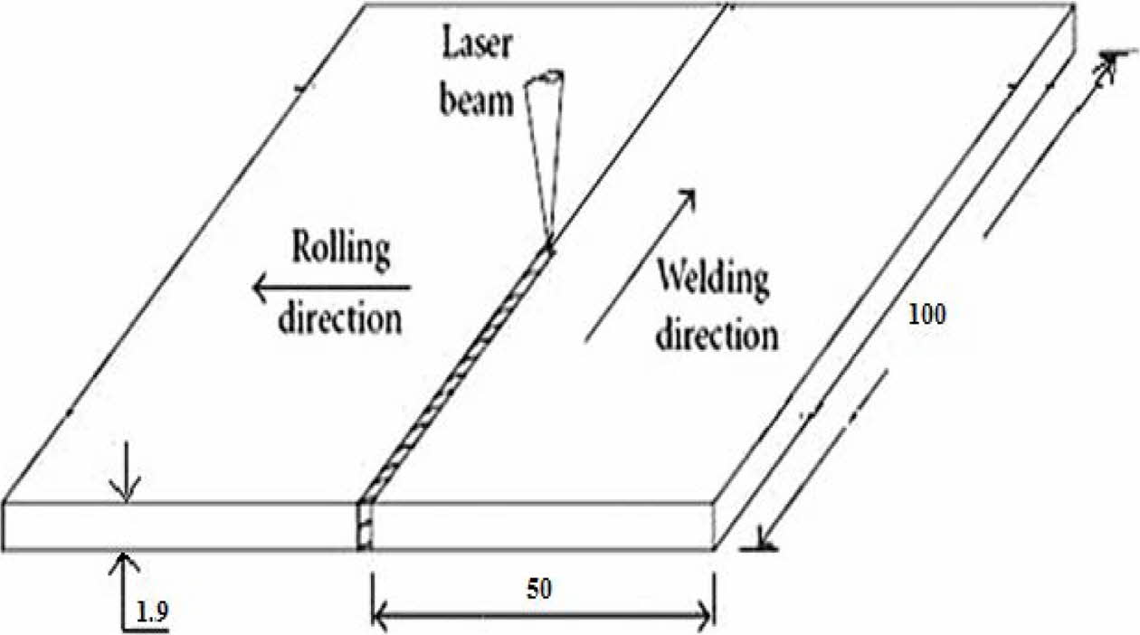
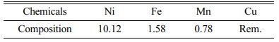
Cupronickel 90/10 (CuNi10Fe1Mn) were used in this investigation. The chemical composition of considered material is shown in Table 1. Rectangular sample plates with the dimensions of 100 x 100 x 1.9 mm3 were prepared and properly aligned in the fixtures of CO2 laser welding machine.
Experimental analysis
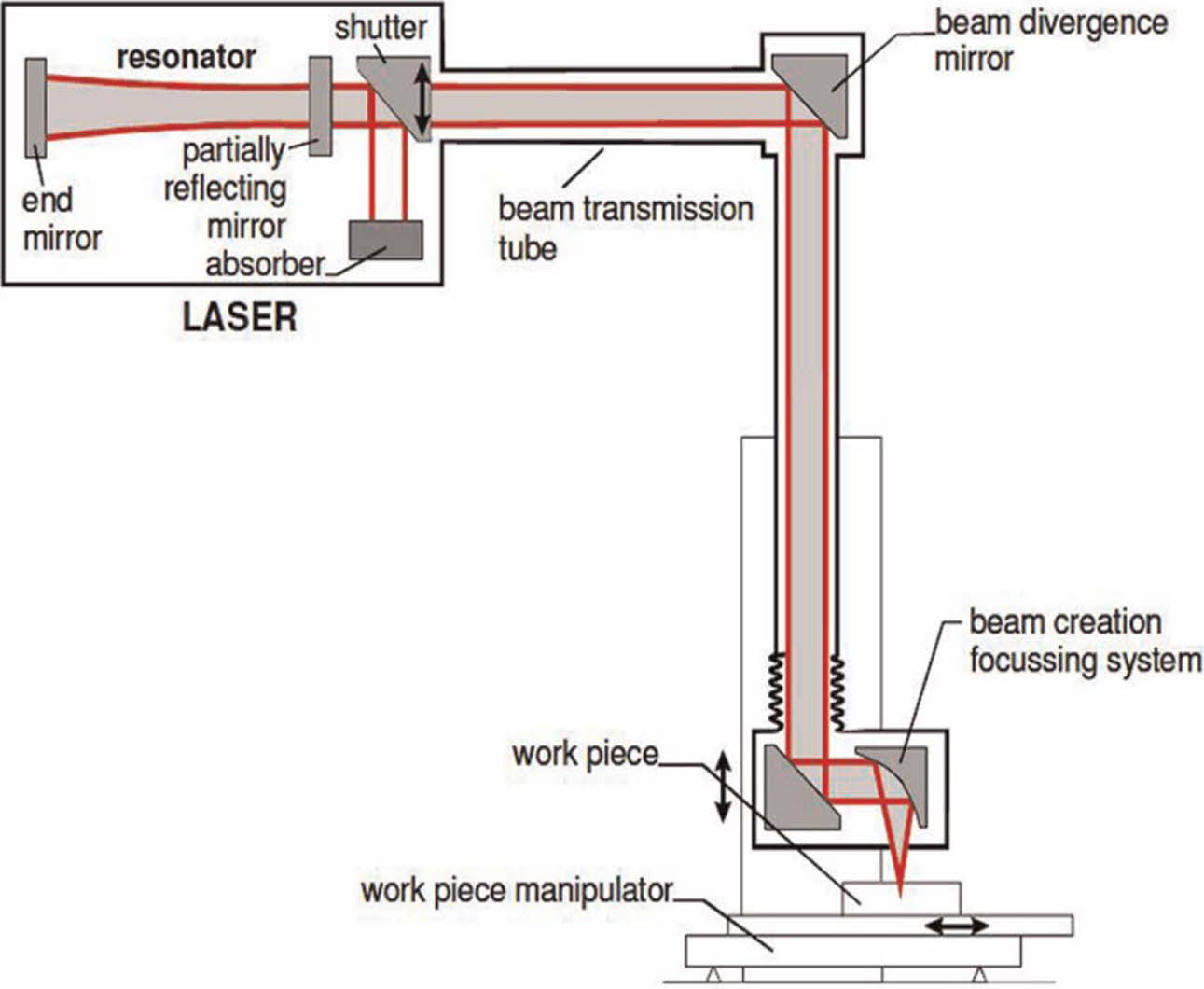
Table 2 shows the process parameters and range of levels considered for the study. Based on these parameters, butt joints were made with CO2 laser beam welding on similar cupronickel alloy. Fig. 1 and 2 shows the schematic representation of CO2 laser beam welding process and dimension of the specimen used. Helium is used as shielding gas (40 L/min) to protect molten bath during welding.
Three different types of experiments were carried out and for each investigation, required standard and procedures were practiced as discussed below.
Tensile test
The weld specimens were subjected to tensile load in order to identify its yield strength, tensile strength and % of elongation. The experiment was conducted on ultimate tensile machine with the capacity of 100 kN based on ASME. The results are recorded and processed in numerical model as one of the evaluation criteria for process parameters.
Hardness
Vickers hardness was examined on three zones namely base metal zone, HAZ and weld zone. Different trails have been made and average value was considered. The experimental outputs are included in the numerical part for further analysis.
Impact test
This test helps to compare the impact properties of weld material with the base metal. The weld specimen was reduced to the dimension suitable for Charpy V- notch test. All the above experimental results are processed through TOPSIS.
Numerical analysis
Many studies focus mainly the experimental programs to prove the reliability of the results whereas some studies compared the experimental and numerical methods. Most of the studies employed Taguchi method or other design of experiment techniques to analyze the process parameter optimization problem. But in virtual applications considering two or three process parameters couldn’t provide clear picture. Hence researchers are in the quest to deal with these multi criteria problems existing in the welding process. Minding this gap, a novel approach (MCDM) was introduced in this study in addition with experimental investigations. Among MCDM tools, there are different strategies exist to evaluate the alternatives, (here different combination of welding parameters is considered as alternatives) and TOPSIS is one of the tools which highly suitable for dealing with multi criteria problems especially under the pressure of various factors. TOPSIS was pioneered by Hwang and Yoon (1981). After this introduction, many researchers adapted TOPSIS in their study. With these considerations, this study employed TOPSIS as a numerical method in combination with experimental investigations to improve reliability and in addition with dealing huge number of process parameters.
Steps involved in TOPSIS methodology is discussed below.
Step 1: Set up initial comparison matrix
In this step, an initial matrix will be formed, in which the alternatives are filled with the weights/values of the concern criteria.
Step 2: Normalized matrix
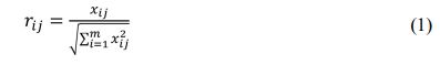
Next step is to normalize the initial matrix derived from previous steps. Eq. (1) is used to derive normalized matrix, in which all values are between 0 to 1.
Step 3: Weighted normalized matrix
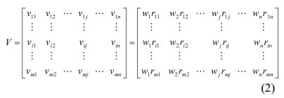
To obtain weighted matrix, assigned weights of each criteria will be manipulated with each and every element in normalized matrix, shown as eq. (2).
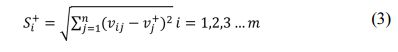
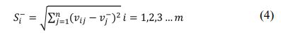
Step 4: Distance between positive and negative solutions
In this step, it is necessary to find out the ideal and negative solution and their distances. D+/Si+ and D-/Si- are the distance between positive and negative solutions respectively, which is shown in eq. (3) and (4).
Step 5: Ranking of alternatives based on closeness coefficients.
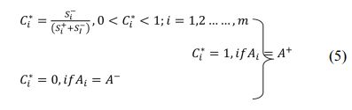
From the ideal and worst distances, the closeness coefficient can be determined (shown in eqation (5)), based on these closeness coefficeint values, the alternatives will be ranked against one another.
|
Fig. 1 Laser welding machine - A schematic representation |
|
Fig. 2 Butt weld specimen dimensions. |
|
Table 2 Considered process parameters of CO2 laser beam welding on cupronickel alloys |
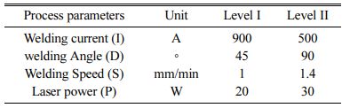
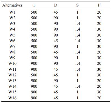
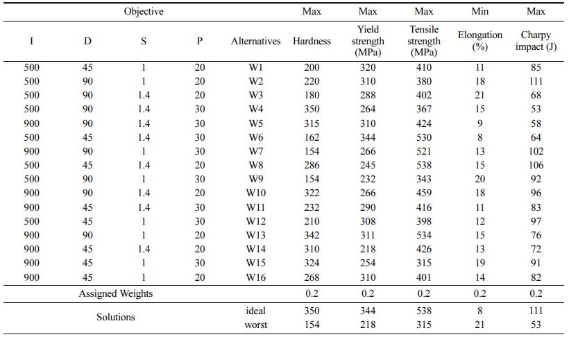
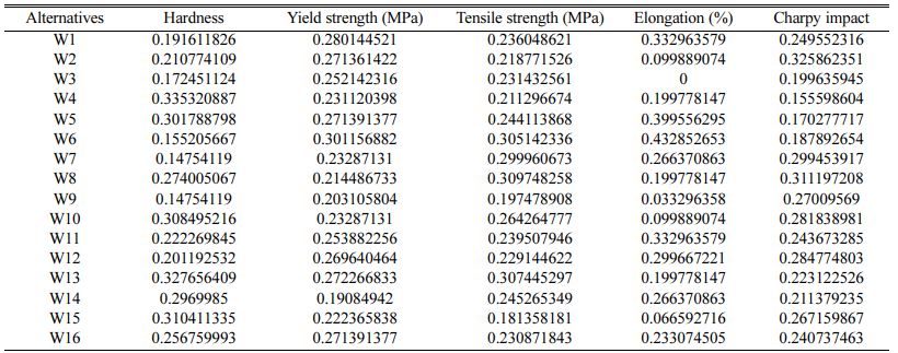
The above steps of TOPSIS are detailed in this section with the problem application. Table 2 shows the process parameters of CO2 laser beam welding on cupronickel alloys. The samples were made based on these combinations of process parameters. These samples are posed to experiments to identify their mechanical properties and these properties was given as input in TOPSIS which are shown in Table 4. Table 3
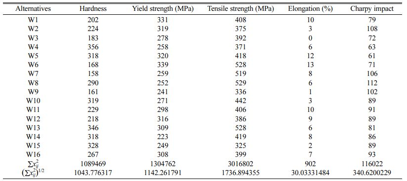
Next step is to normalize the matrix which should range between 0 to 1, Table 5 shows the intermediate and Table 6 shows the final normalized matrix.
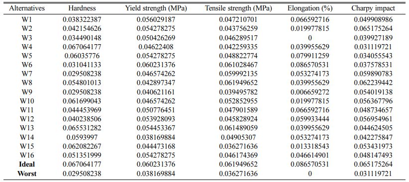
The obtained normalized matrix is further converted into weighted normalized matrix by multiplying the weights of corresponding criteria. Here from the advice of experienced welding technician, all the criteria weights are considered as equal and their summation should be equal to 1. The weighted normalized matrix is shown in Table 7.
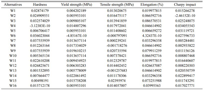
Table 8 and 9 evidences the matrix form with the use of the best and worst weighted normalized matrix solutions.
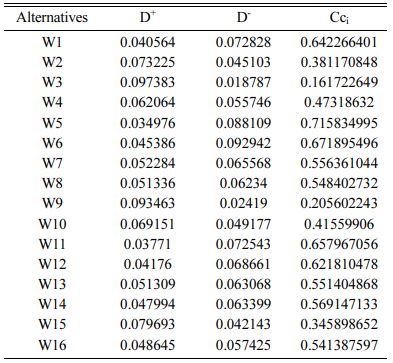
From the above tables, we have to found out the distance between negative and positive solutions of the problem. The positive and negative distances are shown in Table 10 along with closeness coefficient Cci.
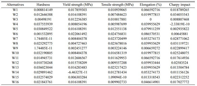
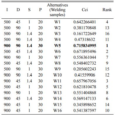
From the numerical analysis based on the mechanical properties of different sample of CO2 laser beam welding on cupronickel alloys, the following rankings has been made (see Table 11) with the assistance of TOPSIS.
Table 11 reveals that welding specimen “W5” (Welding current 900 A, Welding angle 90o, Welding speed 1.4 mm/min and Laser power 30 w) gained more weight and on the other hand, “W9” (Welding current 500 A, Welding angle 90o, Welding speed 1 mm/min and Laser power 30 w) gained less weight. It shows that the optimum selection of process parameters can improve the results up to 50 percent than the least optimal solution. Also, from the results it can be seen that welding current plays a vital role in mechanical characteristics of weld specimen. Because in both best and worst cases of process parameters, the only difference is welding current. In addition, other weld specimen results show the difference in the result which mainly affect with the laser power. Hence, sensitivity analysis on laser power can improve more option in finding appropriate solution. Table 12
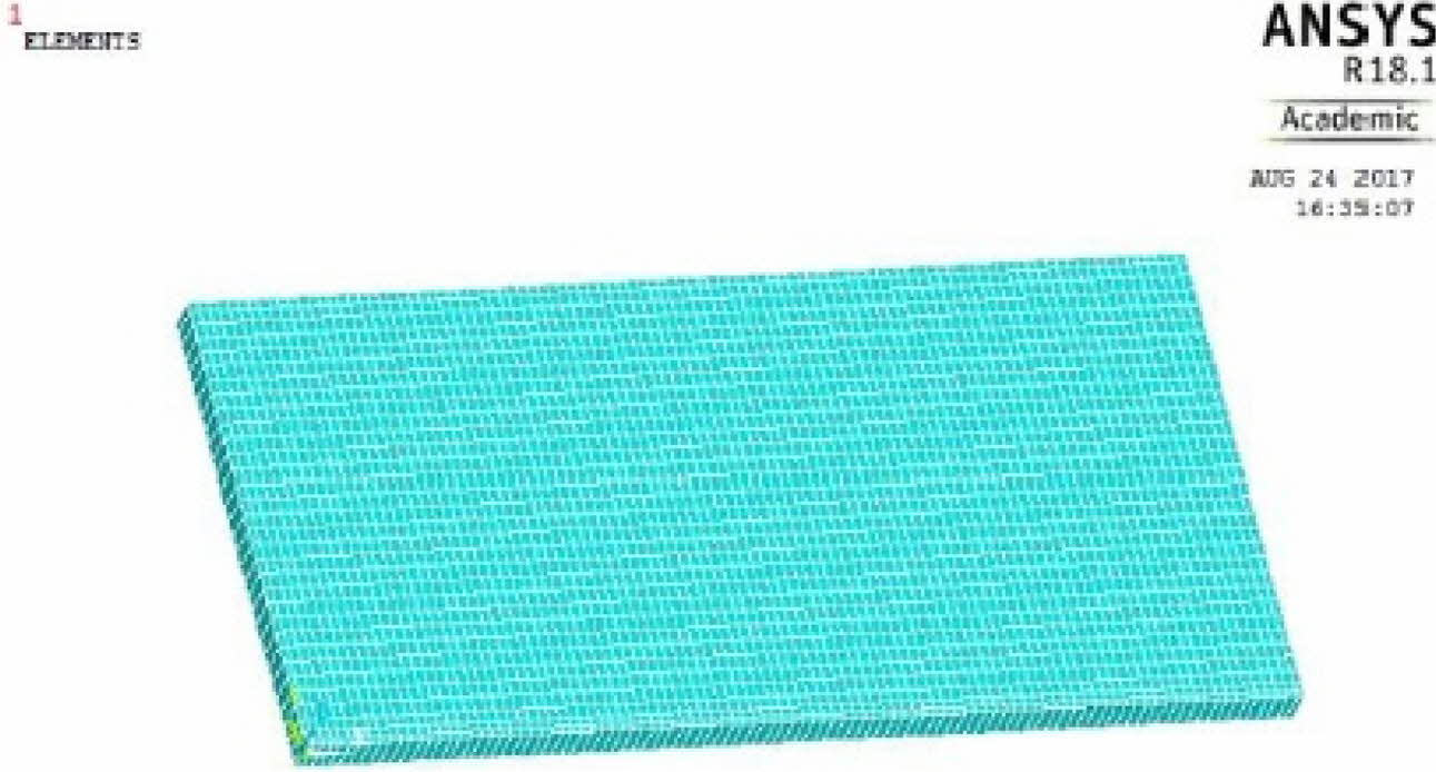
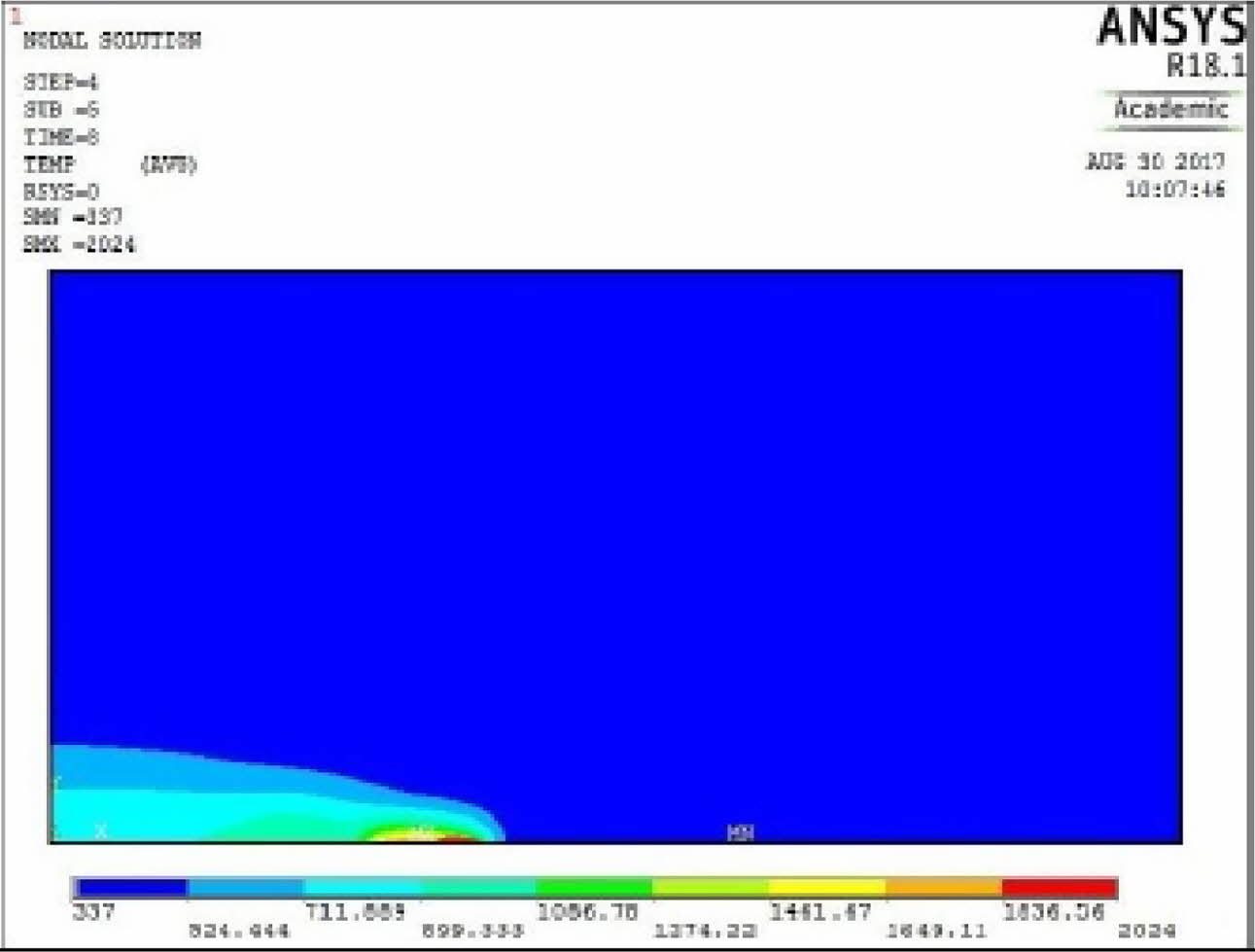
Studies of the thermal distribution during welding process are analyzed by ANSYS 18.1 version. For this study the foremost important factors such as the thermal conductivity, density and specific heat are considered for the weld materials. Weld material meshing plays a very important role for the better result. Fig. 3 show the concept of meshing of weld materials.
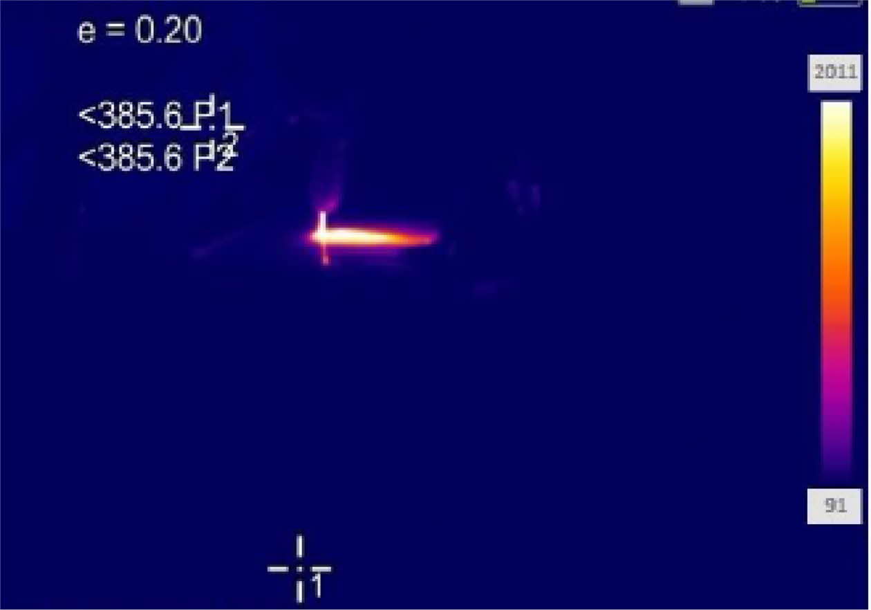
For the welding speed of 3 mm/sec the ANSYS simulation was analyzed at constant heat input 1,600 J/mm. Let us consider the weld efficiency is around 86% and the temperature profile was analysed as represented in the Fig. 4. As a result of comparison, the thermal distribution on the plate was found to be 2,024 ºC at heat speed of 3 mm/sec. But the maximum heat distribution was found as 2,011 ºC by using the thermal camera as represented in Fig. 5. From the result, very close difference is obtained as 13 ºC. It is due to some of the reason such as the content of the air, availability of the shielding gas required for the welding and the distance between thermal camera and plates. The minimum temperature of plate was found as 337 ºC and by thermal imaging camera it was obtained as 91 ºC. This difference is obtained due the atmospheric temperature. From the thermal distribution analysis, it can be clearly seen that temperature decreases with increase in the welding speed.
|
Fig. 3 Meshing on the Single Plate. |
|
Fig. 4 Temperature profile of AISI304 and SA213T22 TIG Welding. |
|
Fig. 5 Temperature measurement of AISI304 and SA213T22 TIG Welding by using thermal camera. |
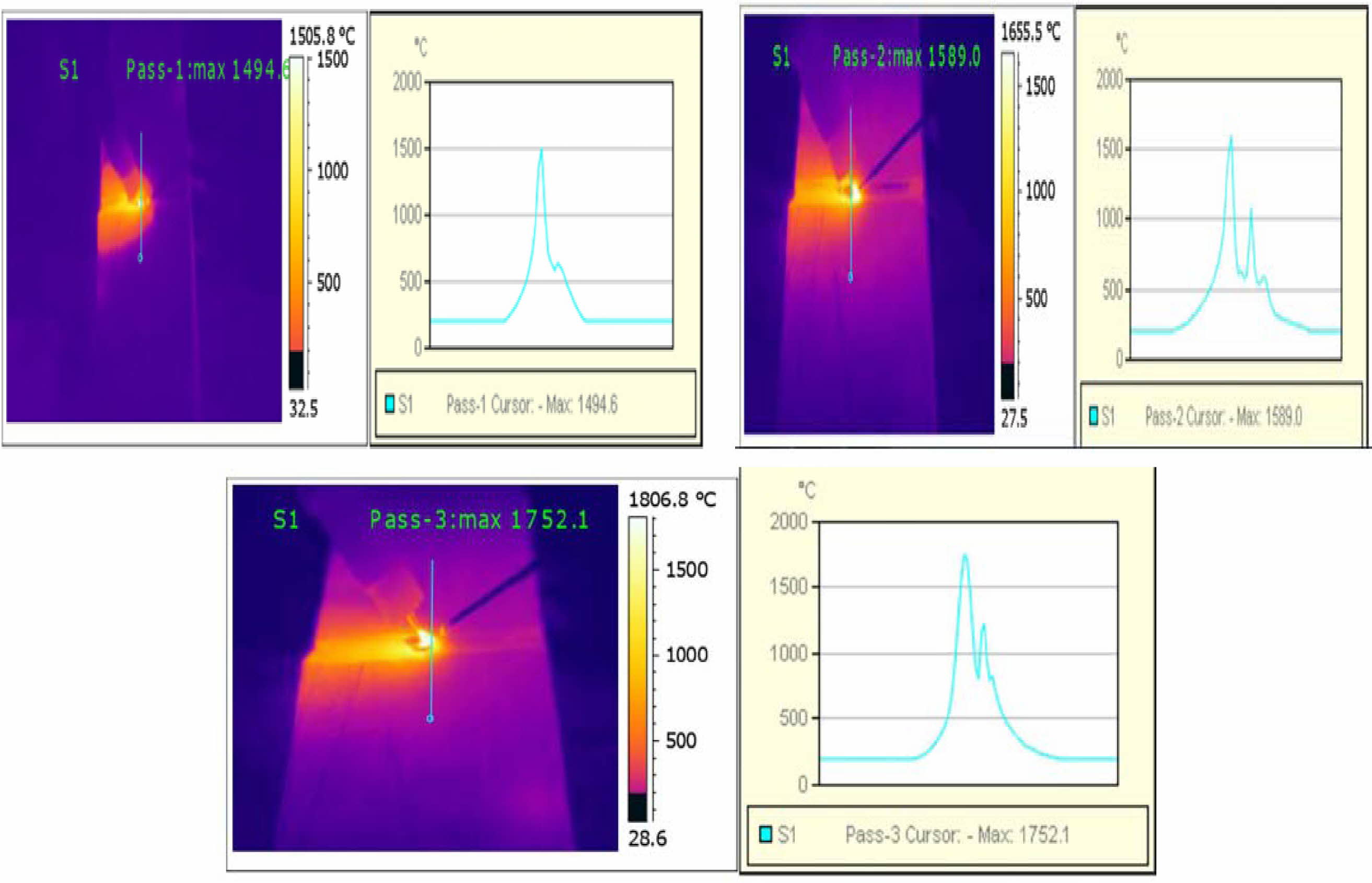
Thermal analysis study is significant in observing the temperature distribution during welding. Hence, the Infra-red thermography is carried out to perform the thermal analysis during the welding process. It is a renowned methodology and beneficial in capturing the temperature in the range of twenty to two hundred degree Celsius. An infra-red photo imager is fixed with the data collector to analyze the temperature distribution over the welding field. Snapshots are created using the above setup to observe the distribution of temperature. Fig. 6 represent the temperature distribution of the welding element
|
Fig. 6 Analysis of Temperature Distribution. |
In this present research work TOPSIS technique was used to optimize the process parameters of CO2 laser beam welding on cupronickel alloys. Four input variables namely laser power, welding current, welding angle and welding speed with two different levels were considered. These four important process parameters are optimized based on the output parameters viz hardness, tensile, yield and energy. Further these experiment results are processed through TOPSIS. By using this technique, welding specimen “W5” (Welding current 900 A, Welding angle 90o, Welding speed 1.4 mm/min and Laser power 30 w), was found to possess the best mechanical properties. It gained maximum overall weight of 0.715834995. The effects of input process parameters on output responses were investigated. The weld has been determined to be of good weld quality based on the mechanical properties of the welded specimen. TOPSIS approach is proven to be a valuable tool for optimizing the welding process parameters.
- 1. N. Saravanan, P. Ganeshan, B. Prabu, V. Yamunadevi, B. NagarajaGanesh, and K. Raja, J. Nat. Fibers (2021) 1-13.
-

- 2. M. Wahba, M. Mizutani, and S. Katayama, J. Mater. Eng. Perform. 25 (2016) 2889-2894.
-
- 3. V. Jeyabalaji, G.R. Kannan, P. Ganeshan, K. Raja, B. NagarajaGanesh, and P. Raju, J. Nat. Fibers (2021) 1-13.
-
- 4. K. Raja, V.S.C. Sekar, V.V. Kumar, T. Ramkumar, and P. Ganeshan, Arab. J. Sci. Eng. 45 (2020) 9481-9495.
-
- 5. P. Muthurasu and M. Kathiresan, J. Ceram. Process. Res. 22 (2021) 697-704.
-
- 6. S.A. Pichuzhkin, S.P. Chernobaev, A.A. Vainerman, and M.M. Veretennikov, Metallurgist 59 (2016) 968-973.
-
- 7. M.P. Chakravarthy, N. Ramanaiah, and B.S.K. Sundara Siva Rao, Proc. Inst. Mech. Eng. Part B J. Eng. Manuf. 228 (2014) 1153-1161.
-
- 8. C. Tan, L. Li, Y. Chen, and W. Guo, Mater. Des. 49 (2013) 766-773.
-
- 9. J. Shen, L. Wen, Y. Li, and D. Min, Mater. Sci. Eng. A 578 (2013) 303-309.
-
- 10. Y.B. Chen, J.C. Feng, L.Q. Li, Y. Li, and S. Chang, Int. J. Adv. Manuf. Technol. 68 (2013) 1351-1359.
-
- 11. M. Behzadian, S.K. Otaghsara, M. Yazdani, and J. Ignatius, Expert Syst. Appl. 39 (2012) 13051-13069.
-
- 12. M. Rajeshwaran, P. Ganeshan, and K. Raja, J. Appl. Fluid Mech. 11 (2018) 257-270.
-
- 13. V. Vignesh Kumar, K. Raja, T. Ramkumar, M. Selvakumar, and T.S. Senthil Kumar, Proc. Inst. Mech. Eng. Part E J. Process Mech. Eng. 235 (2021) 2180-2188.
-
- 14. P.G. Krishnan, B.S. Babu, and K. Siva, J. Ceram. Process. Res. 21 (2020) 157-163.
-
- 15. R. Pandiyarajan and M.P. Prabakaranb, J. Ceram. Process. Res. 21 (2020) 690-698.
-
- 16. B.R. Kumar, N. Chauhan, and P.M. Raole, Adv. Mat. Res. 585 (2012) 430-434.
-
- 17. A. Belhadj, J.-E. Masse, L. Barrallier, M. Bouhafs, and J. Bessrour, J. Laser Appl. 22 (2010) 56-61.
-
- 18. P. Ferro, F. Bonollo, and A. Tiziani, Sci. Technol. Weld. Join. 10 (2005) 299-310.
-
- 19. V. Yamunadevi, K. Palaniradja, A. Thiagarajan, P. Ganeshan, and K. Raja, Mater. Res. Express 6 (2019) 95057.
-
- 20. G. Radhaboy, M. Pugazhvadivu, P. Ganeshan, and K. Raja, Energy Sources, Part A Recover. Util. Environ. Eff. (2019).
-
- 21. V.V. Kumar, K. Raja, V.S.C. Sekar, and T. Ramkumar, J. Brazilian Soc. Mech. Sci. Eng. 41 (2019) 1-14.
-
- 22. B. Suresh Babu, C. Gb, C. Boopathi, T. Pridhar, and R. Srinivasan, J. Ceram. Process. Res. 19 (2018) 69-74.
- 23. C. Chanakyan and S. Sivasankar, J. Ceram. Process. Res. 21[6] (2020) 647-655.
-
- 24. L. Shi, J. Chen, C.S. Wu, and L. Fu, Sci. Technol. Weld. Join. 26 (2021) 363-370.
-
- 25. M. Gao, X.Y. Zeng, and Q.W. Hu, Sci. Technol. Weld. Join. 11 (2006) 517-522.
-
- 26. N. Selvakumar, B. Gnanasundarajayaraja, and P. Rajeshkumar, Exp. Tech. 40 (2016) 129-135.
-
- 27. P. Ferro, F. Bonollo, and A. Tiziani, Sci. Technol. Weld. Join. 10 (2005) 299-310.
-
- 28. K.A.S. Lewise and J.E.R. Dhas, Mater. Manuf. Process. 37 (2022) 34-42.
-
 This Article
-
2022; 23(3): 278-286
Published on Jun 30, 2022
- 10.36410/jcpr.2022.23.3.278
- Received on Oct 18, 2021
- Revised on Jan 25, 2022
- Accepted on Jan 27, 2022
Services
- Abstract
introduction
materials and methods
application of topsis
results and discussion
thermal distribution using ansys simulations
thermal analysis during welding
conclusion
- References
- Full Text PDF
Shared
Correspondence to
- S. Karthick
-
Department of Mechanical Engineering, J.J. College of Engineering and Technology, Tiruchirappalli - 620009, Tamil Nadu, India
Tel : +919788220668 - E-mail: skarthick1480@gmail.com
Clean-Energy Research Institute(CRI), Hanyang University, 222, Wangsimni-ro, Seongdong-gu, Seoul, 04763, Korea
E-mail: jcpr@hanyang.ac.kr