


- Parametric optimization of wear parameters on wear rate and coefficient of friction for hybrid (A356 +TiB2+ ZrO2) metal matrix composites
Kanakaraj Aa,*, Mohan Rb and Viswanathan Rc
a Department of Mechanical Engineering, Thiagarajar Polytechnic College, Salem, India
bDepartment of Mechanical Engineering, Sona College of Technology, Salem, India
cDepartment of Mechanical Engineering, AVS Engineering College, Salem, IndiaThis article is an open access article distributed under the terms of the Creative Commons Attribution Non-Commercial License (http://creativecommons.org/licenses/by-nc/4.0) which permits unrestricted non-commercial use, distribution, and reproduction in any medium, provided the original work is properly cited.
In this study, the TiB2 & ZrO2 incorporated A356 based hybrid composites were fabricated via stir casting method and also the wear parameters such as wear rate (WR) and coefficient of friction (COF) were optimized using Taguchi-Grey Relational Approach (GRA). It was found that 10 N of load, 2 m/s of Sliding velocity, 1500 m of sliding distance and reinforcement of 0.5%TiB2+ 2.5%ZrO2 nano particle as the optimal conditions to acquire the minimum WR and COF. The uniform dispersion of nano particles in the matrix alloy was found out with microscopic examination. Analysis of variance results revealed load and incorporation of nano particles as the factors that have dominant influence on WR and COF respectively in that order. Significant improvement in wear resistance rate was obtained with the addition of TiB2 and the COF prominently got reduced with the reinforcement of increased wt% of ZrO2
Keywords: A356 alloys, Hybrid composite, Wear rate, Coefficient of friction and GRA
The usage of MMCs (Metal Matrix Composites) in automotive and transportation industry is expanding fast now-a-days. Modern industries are focusing mainly on replacement of steel and other commercial materials with MMCs. Due to excellent properties like high wear resistance, strength, ductility and less weight, MMCs receive attention for usage by the automotive industry [1]. AMCs (Aluminum Matrix Composites) are becoming popular as they are inexpensive and have the advantage of high strength to weight ratio. A356 Aluminum alloys are widely used in automobile industry for production of automotive parts like oil pans, pump bodies, machine and truck chassis parts etc. Due to widespread appli- cations, wear and frictional resistance of A356 aluminum alloy requires further investigation for improvement. [2-3]. Casting method and mechanical alloying are the two common methods adopted for AMC fabrication. Among them, liquid metallurgy techniques such as pressure infiltration, stir casting and spray deposition are widely used [4-5]. Chidozie et al. [6] studied effects of age hardening on AMC and also optimized the hardening parameters of A356/Cow horn particulate composite that was specifically made for brake drum applications. Based on the research, it was stated that Response surface methodology could be used for optimizing the parameters of annealing and age hardening processes.
Donanta Dhaneswara et al. [7] investigated the mechanical properties of Nano SiC reinforced A356 aluminum alloy developed with modified stir casting process. The improved results obtained from the com- posite were 176.1Mpa of Tensile strength and material elongation of 6.92%. The wear resistance and hardness of the composite increased with the addition of Nano SiC to A356 Aluminum alloy. Sathish et al. [8] analysed the wear behavior of Aluminum 7075 reinforced with SiC using Taguchi approach. For performing the experi- ments 1 m/s, 2 m/s and 3 m/s were chosen as sliding velocities for the sliding distances of 1000 m, 1400 m and 1800 m respectively. Based on the investigation, sliding distance was found to be the highly influenc- ing parameter on wear rate. The influence of sliding distance was 45.64% on wear rate which was a higher value compared to reinforcement and sliding velocity. Satyanarayana et al. [9] studied the effect of tribological parameters on friction response of A356 aluminum alloy with graphite/granite particle reinforcement. It was found from the study that coefficient of friction of reinforced A356 alloy decreased with increase in reinforcement but the coefficient of friction increased with the rise in sliding time. As per the ANOVA analysis, sliding time was the highest contributing factor with a contribution of 48.51% and load held the second position with 21.93% of contribution.
Akbari et al. [10] studied the tensile and fracture behavior of Nano/Micro TiB2 particle reinforced A356 alloy. The report stated that rise of porosity was observed with high volume fraction of reinforcement and reduced particle size. High toughness was observed in A356 com- posite at the volume fraction of 1.5% of TiB2. Titanium diboride (TiB2) is a commonly used ceramic material for obtaining high strength, hardness and corrosion resistance. It is widely used in erosive, abrasive and highly corrosive applications. Compared to other ceramic particles, TiB2 can be easily reinforced in liquid alu- minum. TiB2 acts as a strengthening agent of AMCs [11-13]. Addition of Zirconia (ZrO2) is another common reinforcement material for AMCs. Girisha et al. [14] studied the material behavior of Al356 with zirconium oxide as reinforcement. Improvement in hardness and wear resistance with the reinforcement of Zirconium oxide nano particle was reported. Satish Babu Boppana et al. [15] studied and characterized nano graphene and ZrO2 reinforced Al6061 AMCs. Improved material strength and percentage of elongation were noted with the addition of ZrO2 in the base alloy of Al 6061. Optimization in material research is much needed to optimize the fabrication parameters as well as mass fraction levels of reinforcements. Both single objective and multi objective level optimization methods are commonly used in material research. PCA, TOPSIS, GRG and GRA are the dominating optimization techniques used in recent researches [16-20].
Based on the past researches, it was noticed that new A356 AMCs with enhanced wear and frictional behaviour are required for automobile sector. Normally, the main objectives were to improve the hardness and strength of the AMCs. Since A356 is widely used in automobile sector and the components mostly involve moving and sliding movements, study of its wear resistance and frictional behaviour is essential. This research is aimed to fabricate new A356 aluminum alloy composite by reinforcing TiB2 and ZrO2 through stir casting method and also to optimize the process parameters. Based on their strong, malleable and ductile properties, TiB2 and ZrO2 are selected as reinforcements. Nano reinforcement was preferred as it provides better tribological performance of AMCs [10, 21-22]. For performing optimization, load, sliding velocity, sliding distance and combined mass fraction of TiB2 and ZrO2 were selected as input parameters. Wear rate and COF were considered as output parameters.
Work material
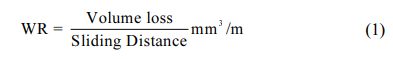
In this work, A356 aluminum alloy is used as matrix material with the composition of Al: 92.16%, Si: 6.989%, Fe: 0.161%, Cu: 0.025%, Mn: 0.055%, Mg: 0.371%, Cr: 0.028%, Ni: 0.060% and others 0.151%. TiB2 and ZrO2 are used as reinforcements with the average particle size of 80 nm. The SEM images of nano parti- cles are shown in Fig. 1. The combined mass fraction of TiB2 and ZrO2 with different weight percentages are used for the composites’ fabrication.
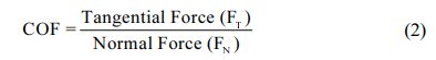
The hybrid composites were fabricated via bottom pouring stir casting machine with vacuum die casting attachment. Two fin blade stirrers were used for mixing of reinforcement particles (TiB2 and ZrO2) with the matrix material (A356 alloy) [21]. Three diverse com- bined mass fractions of TiB2 and ZrO2 were used to produce hybrid MMCs as mentioned in Table 1. Firstly the A356 alloy was converted to molten stage with the help of electrical induction heating system in a graphite crucible at 750 oC in the inert atmosphere of nitrogen gas. For attainment of better turbulence, the mechanical stirring system was introduced in the molten metal at a constant speed of 500 rpm. Moreover good wettability was achieved by adding 1 wt.% of Mg and stirred properly. The mixing of TiB2 and ZrO2 particles along with base molten metal was completed in an optimized manner. Lastly, the composite slurry was poured into the graphite coated die made of steel. It is obvious from SEM microscopic images (Fig. 2) that TiB2 & ZrO2 nano particles are uniformly dispersed in the matrix alloy. Next, the hardness of the hybrid composite specimen was assessed using micro Vickers hardness tester with a pay load of 1 kg. The hardness values of A356/TiB2-ZrO2 composites were 62 Hv, 64 Hv and 68Hv for A356 Al alloy with 0.5% TiB2 + 2.5%ZrO2, 1.5% TiB2 + 1.5%ZrO2 and 2.5% TiB2 + 0.5%ZrO2 respectively.
Experimental setup
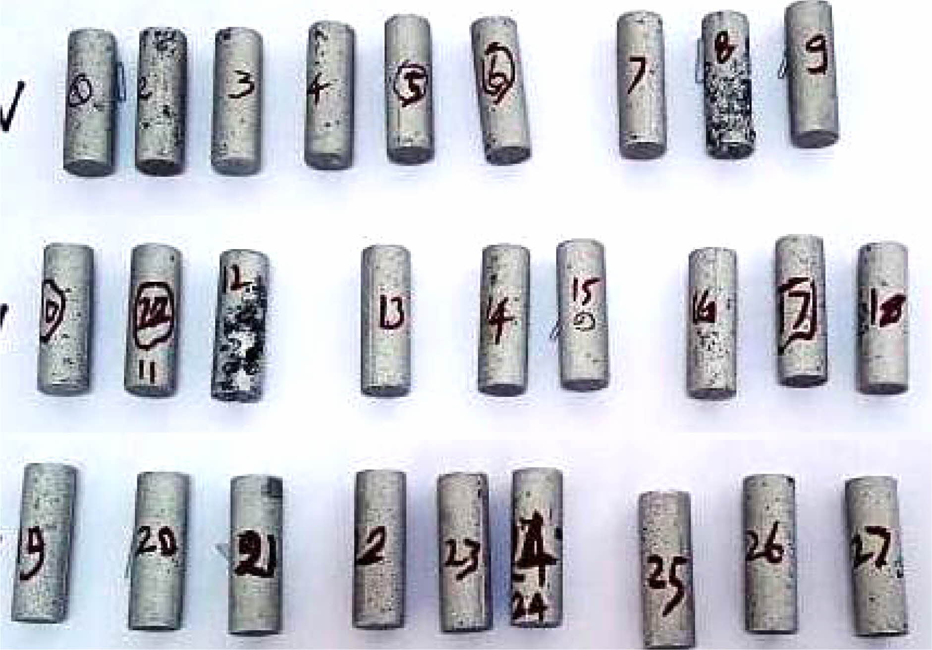
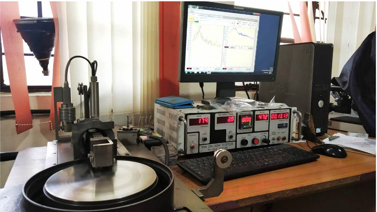
The fabricated hybrid composite specimens were shaped in the form of cylinders with 30 mm diameter and 300 mm length. The specimens were machined for dimensions suitable to wear test with 10 mm diameter and 30 mm length as the middle section of the cylindrical composites are normally used to assess the wear re- sistance of the composites [10] and it is shown in Fig. 3. Wear tests were conducted on the basis of L27 OA design under dry conditions using pin-on-disc apparatus (Fig. 4) at room temperature in accordance with ASTM G99-95. The hardness of the disc used in the Pin-on-Disc machine is 60HRC. The wear test parameters were selected as per the earlier findings in the literature and are given in Table 1 [22-27].
The electronic balance of 0.0001 g precision was used to measure the wear loss of the specimen. Each sample was cleaned with acetone before and after wear tests to remove wear debris. The variations in the weight observed before and after the test provided the wear loss of the composites through dry sliding, which was transformed into the volume loss. The wear rate (WR) was computed using Eq. (1).
The coefficient of friction (COF) was attained by using Eq. (2). For the calculation, FT is found from the load cell fixed in the pin-on-disk apparatus.
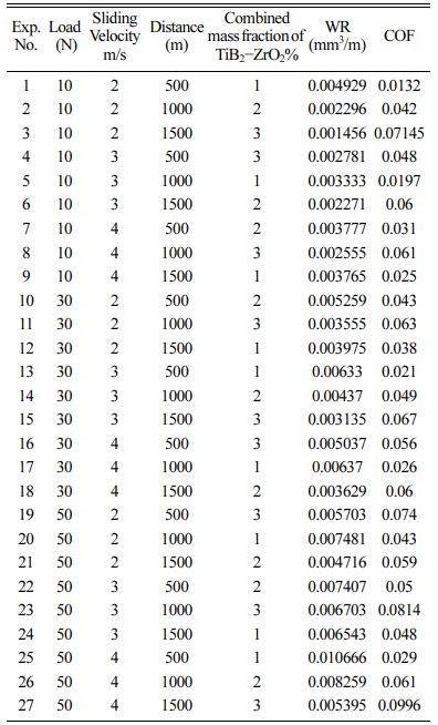
The experimental results are specified in Table 2.
|
Fig. 1 SEM images reinforcements: (a) TiB2 and (b) ZrO2. |
|
Fig. 2 SEM micrographs of cast A356 hybrid composites: a) A356/0.5% TiB2 + 2.5%ZrO2, (b) A356/1.5% TiB2 + 1.5%ZrO2, and (c) A356/2.5% TiB2+ 0.5%ZrO2. |
|
Fig. 3 Specimens for Wear test. |
|
Fig. 4 Experimental setup for wear test. |
Single Objective Optimization:
This work is intended for finding optimum factor levels that provide minimum WR and COF. Therefore lower the better is desired and the expression for computing signal to noise ratio is given by Eq. (3).
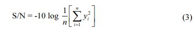
Here, n = No. of observations in this study, y = ex- perimental result.
The mean and S/N ratio plot was achieved by using Minitab19 software.
Analysis of Wear rate (WR) and coefficient of friction (COF)
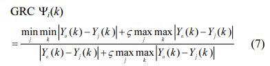
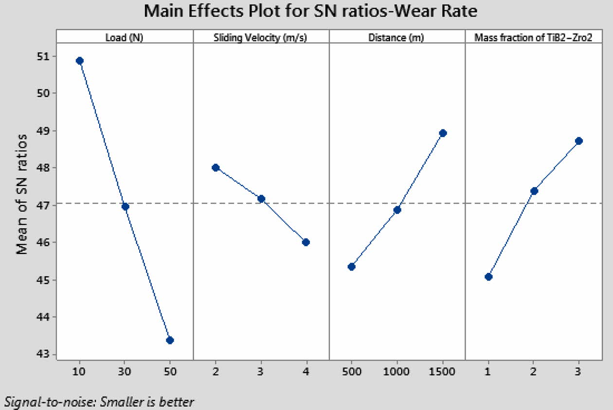
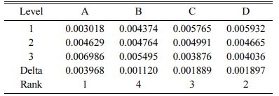
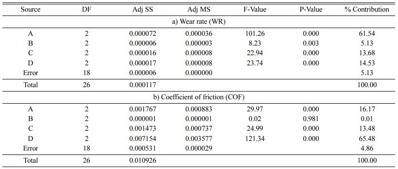
The mean and SN ratio plots for wear rate (WR) are provided in Fig. 5 and 6. The WR increased with an increase in both load and sliding velocity, apparently owing to growth in the deformation of the matrix by applied load. It decreases moderately with increasing distance and lower WR is observed at the reinforcement of 2.5% TiB2. Optimal WR is attained at the load of 10N, sliding velocity of 2 m/s, distance of 1500 m and reinforcement of 2.5% TiB2 + 0.5%ZrO2. Analysis of Variance was used to attain the parameters influence to WR and COF and given in Table 5 [28-30]. It is evident from Table 3 and Table 5 that load has greater influence (61.54%) on WR followed by reinforcement of TiB2 + ZrO2 particles (14.53%), Sliding distance (13.68%) and sliding velocity (5.13%). It can be noticed from the results that the addition of TiB2 has a significant influence on increasing wear resistance rate [10]. Higher hardness value is attained for 2.5% TiB2 composition compared to other combinations. This is due to increase of nano reinforcement in the matrix. The presence of hard particles at nano size offer more resistance to plastic deformation and hence high hardness is witnessed. Reduction in reinforcement size results in considerable raise in the surface area. Moreover reinforcements in the form of nanoparticles that are suspended in the lubricant formulations can penetrate the small gaps between two surfaces and change the tribological properties of the AMCs [31-32]
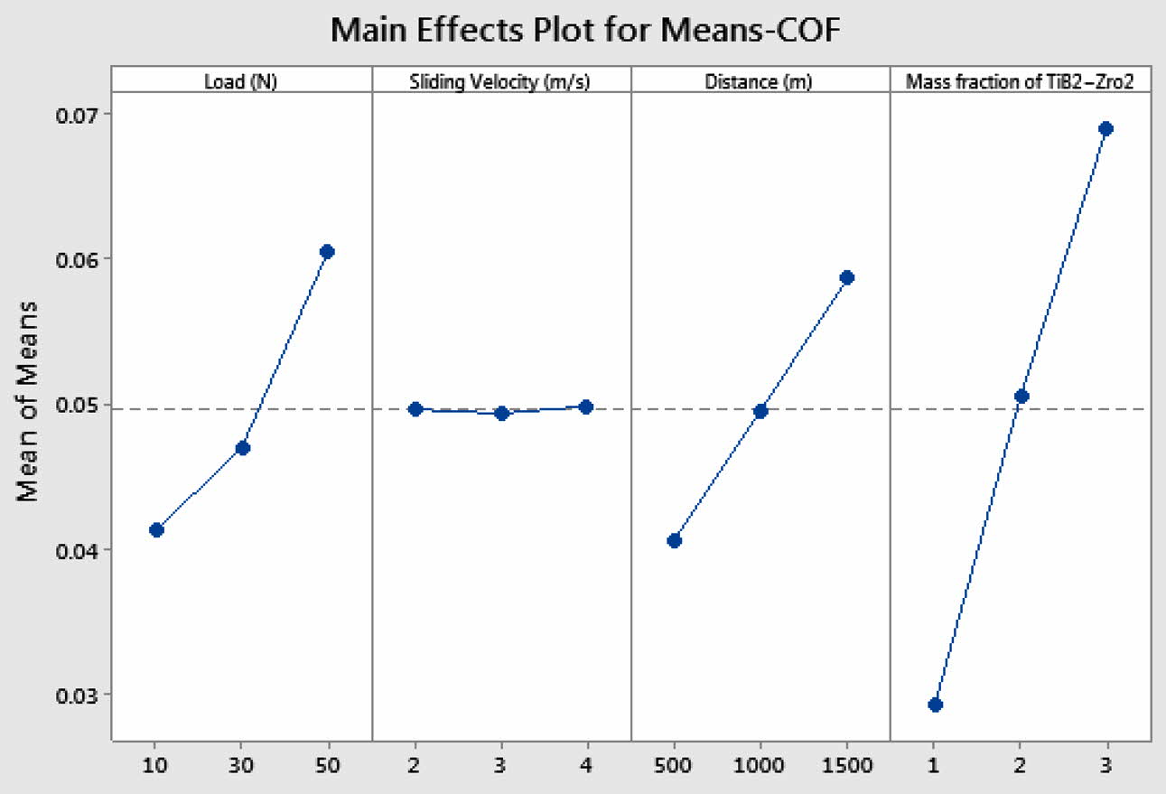
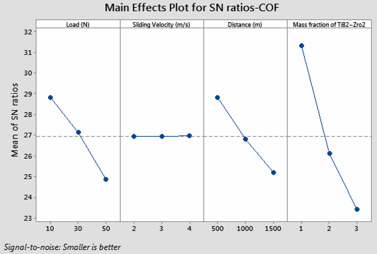
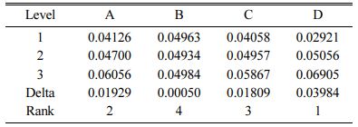
The mean and SN ratio plot for coefficient of friction (COF) are provided in Fig. 7 and 8. The COF increased with the increase of load and sliding distance. No significant change was observed in COF with respect to sliding velocity. It is evident that the COF get reduced with the increase in the wt.% of ZrO2 in all these Al hybrid composites. This is because of the presence of evenly distributed ZrO2 particles and the characteristic strength of the ceramic. This result agrees well with the findings of Naguib G. Yakoub 2020 [22]. Minimum COF was observed at load 10 N, sliding velocity 2 m/s, distance 500 m and reinforcement of 0.5% TiB2 + 2.5%ZrO2. Reinforcement of TiB2 + ZrO2 particles has exhibited dominant influence (65.48%) on COF followed by applied load (16.17%) and sliding distance (13.48%) as observed in Mean response of Table 4 and analysis of variance of Table 5.
Analysis of Variance
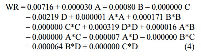
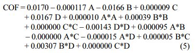
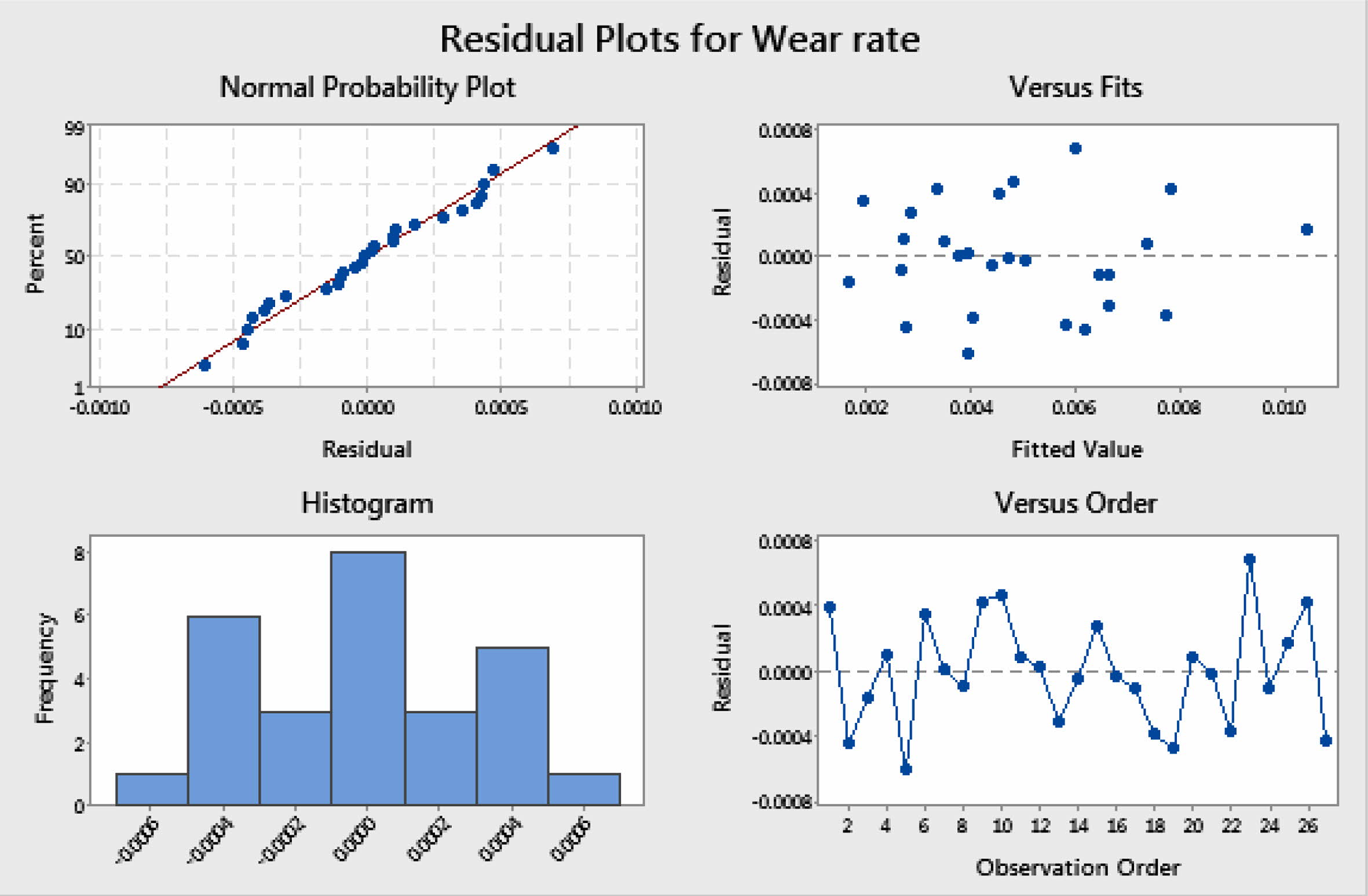
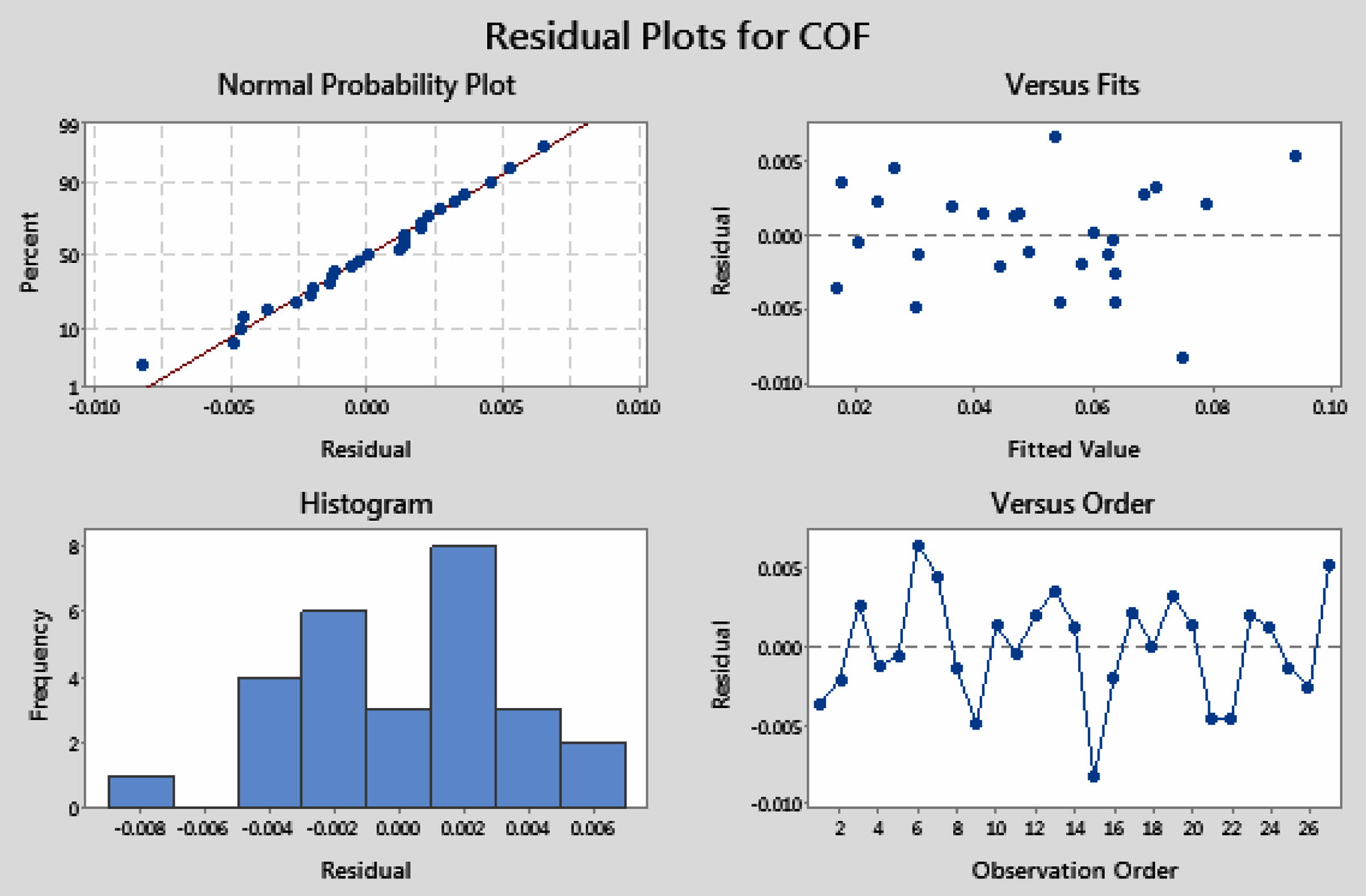
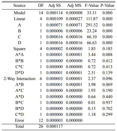
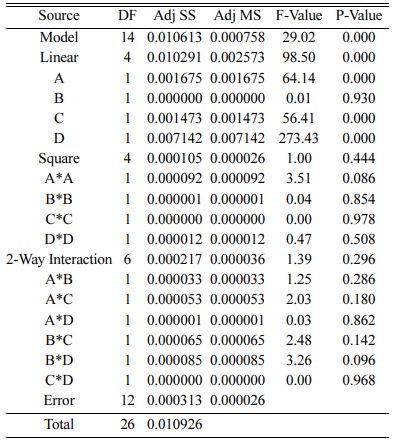
The preferred second order quadratic models for WR and COF are denoted in Eq. (4) and (5). The ANOVA outcomes of WR and COF are shown in Table 6 and 7 respectively. The consistency of the models is acknowl- edged with better R2 Value [33-34]. Predicted R2 and Adj. R2 values point out better outcomes with high precision. According to ANOVA study, for WR, R2 = 97.51%, R2 (adj) = 94.60% and R2 (Pre) = 87.71%. Likewise for COF, R2 = 97.13% R2 (adj) = 93.78% and R2 (Pre) = 83.23%. Based on the R2 values, it can be observed that the experimental order reveals high confident level of the model with 90% confidence and significance. Residual plots for WR and COF are dis- played in Fig. 9 and 10, and reveal that all the results fall on the mean value. This imply that the test parameters of this study are dominant ones and at optimum levels.
Multi objective Optimization:
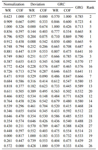
The main aim of this work is the minimization of WR and COF of the fabricated hybrid MMCs using GRA technique. The composite with minimum WR and COF will be denoted as optimum, hence the calculation is based on ‘‘Lower is better’’ theory. As the first step in this analysis, the experimental results (WR and COF) are normalized in the range between 0 and 1 with help of Eq. (6) and are presented in Table 8.
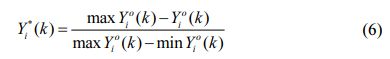
Where Yio(k) is original sequence, Yi*(k) is normalized sequence
After normalization, the grey relational coefficient (GRC) is computed using the below expression.
Where, distinguishing coefficient ζ = 0.5 is mostly used. The mean value of the GRC is the grey relational grade (GRG). Consequently, the GRG is expressed in Eq. (8):
The GRG denotes the correlation among the reference order and the comparability order, which is given in Table 8.
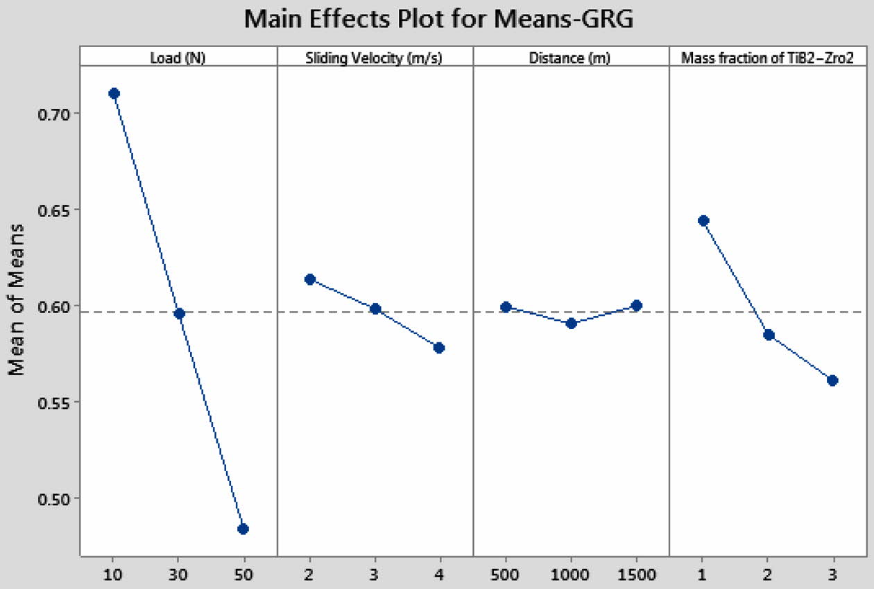
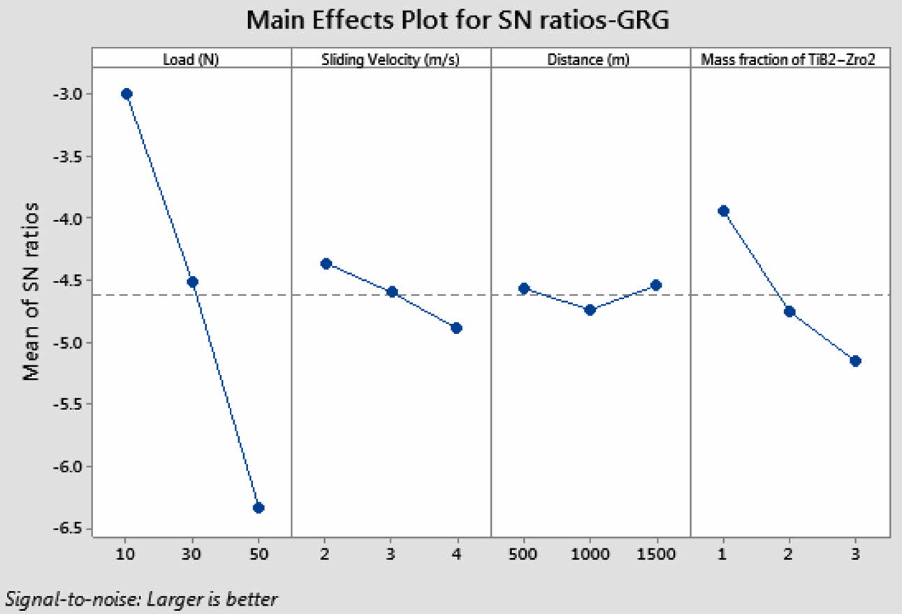
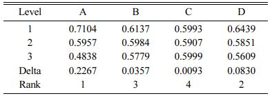
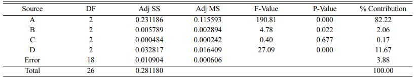
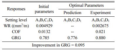
Based on the mean and S/N ratio graphs (Fig. 11 and 12) for GRG, 10 N load (Level 1), 2 m/s Sliding velocity (Level 1), 1500 m distance (level 3) and reinforcement of 0.5%TiB2 + 2.5%ZrO2 nano particles (Level 1) provide the optimal conditions to get the minimum WR and COF. The mean and analysis of variance of GRG (Table 9 and 10) indicates load as the strongest impact parameter on dry sliding performance characteristics with a contribution of 82.22% followed by reinforcement of TiB2 + ZrO2 particles. The parameters of sliding velocity and distance have not shown significant effects on simultaneous optimization of WR and COF.
Validation experiments
The prediction of GRG for dry sliding parameters is obtained by using Eq. (9) [35-36] and it is presented in Table 11.
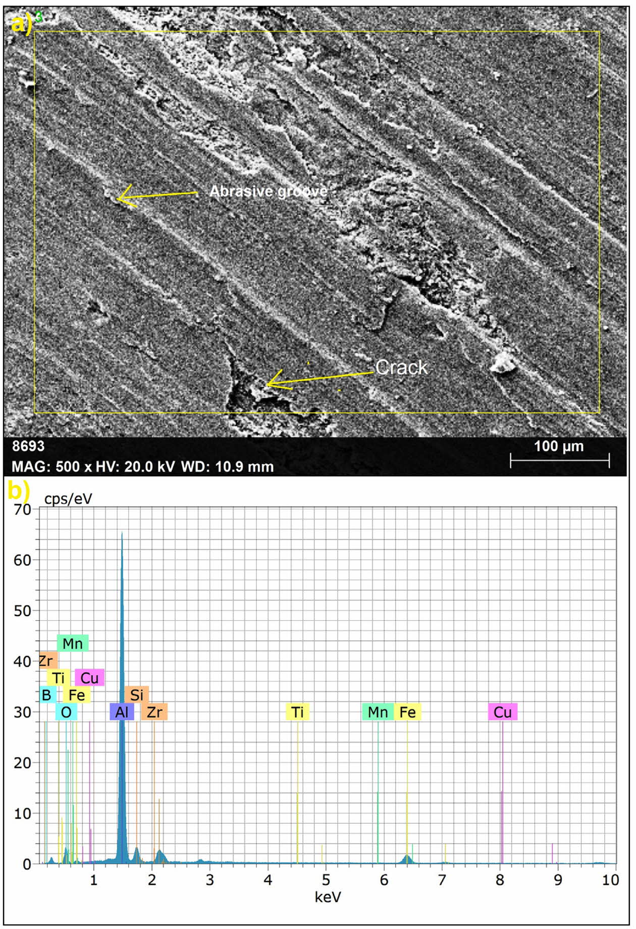
Optimized results were verified with validation test (Table 11). At minimum load of 10 N, sliding velocity of 2 m/s, maximum distance of 1500 m and reinforce- ment composition of 0.5%TiB2 + 2.5%ZrO2 the outputs produced were 0.002675 mm3/m WR, 0.021 COF. WR value is reduced considerably by 45% due to the addition of 2.5%ZrO2 with A356 alloy [37]. COF value slightly increased from 0.0132 to 0.021. It can be observed from the results that the addition of 0.5%TiB2 + 2.5%ZrO2 has a significant influence on increasing wear resistance rate and reducing COF. GRG value is found to have improved from earlier test results, hence optimal wear parameters for multiple responses could be achieved by this method. From the Fig. 13, it is obvious that nanoparticles play a major role in deter- mining the size of wear debris. This is owing to the enhancement in the wear resistance of the composites with addition of ZrO2. EDS examination showed Al, Si, Oxygen and traces of iron, which confirms the presence of oxide materials. The existence of oxidized materials enables the formation of oxide tribolayers [38-39]. In the case of nano composites too, friction can produce substances like oxides, but it would be at molecular level [40]. When friction occurs at nano-scale, some of the particles get involved in friction in the interface areas whereas other particles may slide on the surface without friction (frictionless state) leading to friction duality [41].
|
Fig. 5 Mean effect plot for WR. |
|
Fig. 6 S/N ratio plot for WR. |
|
Fig. 7 Mean effect plot for COF. |
|
Fig. 8 S/N ratio plot for COF. |
|
Fig. 9 Residual plots for WR. |
|
Fig. 10 Residual plots for COF |
|
Fig. 11 Mean effect plot for GRG |
|
Fig. 12 S/N ratio plot for GRG |
|
Fig. 13 EDS graph of worn surface at optimal conditions. |
The present study includes fabrication of A356 hybrid composites with the incorporation of TiB2 & ZrO2 particles in different proportions and also con- ducting wear tests to optimize the parameters via Taguchi-GRA approach.
> According to GRA, 10N load, 2m/s Sliding velocity, 1500 m distance and reinforcement of 0.5%TiB2 + 2.5%ZrO2 nano particles are the optimal conditions to acquire minimum WR and COF.
> WR of 0.002675 mm3/m and COF of 0.021 are obtained at optimal conditions and verified via validation test.
> Among the four wear parameters, load has shown highest impact (61.54%) on WR followed by reinforcement of TiB2 + ZrO2 particles on the basis of ANOVA results and found that the addition of TiB2 imparts significant improvement in wear resistance rate.
> From ANOVA results, it is learnt that incorporation of nano particles has the most dominant effect (65.48%) on COF and also the COF get greatly reduced when the addition of wt% of ZrO2 increased further.
> It is evident from the microscopic images that TiB2 & ZrO2 particles are evenly dispersed in the matrix and these hard particles lend increased resistance to wear.
- 1. A. Kheder, G. Marahleh and D. Al-Jamea, J. Mech. Indus. Eng. 5 (2011) 533-541.
- 2. A. Mahazery, H. Abdizadeh and H. Baharvandi, Mater. Sci. Eng. 518 (2009) 61-64.
-

- 3. B.M. Viswanatha, M. Prasanna Kumar, S. Basavarajappa and T.S. Kiran, J. Eng. Sci. Tech. 8 (2013) 754-763.
- 4. S.A. Sajjadi, M.T. Parizi, H. REzatpour and A. Sedghi, J. Alloys. Compd. 511(2012) 226-231.
-
- 5. M. Maurya, S. Kumar, and V. Bajpai, J. Rein. Plas. Comp. 38 (2019) 267-298.
-
- 6. C.C. Nwobi-Okoye and B.Q. Ochieze, Def. Technol. 14 (2018) 336-345.
-
- 7. D. Dhaneswara, A. ZulfiaSyahrial, and M.T. Ayman, Proce. Eng. 216 (2017) 43-50.
-
- 8. T. Sathish and S. Karthick, J. Mater. Res. Technol. 9 (2020) 3481-3487
-
- 9. T. Satyanarayana, P.S. Rao, and M.G. Krishna, Heliyon 5 (2019) e01770.
-
- 10. M.K. Akbari, H.R. Baharvandi, and K. Shirvanimoghaddam, Mater. Des. 66 (2015) 150-161.
-
- 11. M. Emamy, M. Mahta and J. Rasizadeh, Comp. Sci. Technol. 66 (2006) 1063-1066.
-
- 12. H. Abdizadeha, H.R. Baharvandi, and K.S. Moghaddam, Mater. Sci. Eng. 498 (2008) 53-58.
-
- 13. G. Kumar, S. Seetharaman, and M. Gupta, Mater. Charact. 94 (2014) 178-188.
-
- 14. K.B. Girisha and H.C. Chittappa, I.J. Innov. Res. Sci. Eng. Tech. 2 (2013) 3627-3637.
- 15. S.B. Boppana, S. Dayanand, M.R.A. Kumar, V. Kumar, and T. Aravinda, J. Mater. Res. Tech. 9 (2020) 7354-7362.
-
- 16. N. Sivashankar, R. Viswanathan, K. Periasamy, R. Venkatesh, S. Chandrakumar 37 (2021) 214-219.
-
- 17. S. Ramesh, R. Viswanathan, and S. Ambika, Measurement 78 (2015) 63-72.
-
- 18. A. Kannan, R. Mohan, R. Viswanathan, and N. Sivashankar, J. Mat. Res. Tech. 9 (2020) 16529-16540.
-
- 19. R. Viswanathan, S. Ramesh, S. Maniraj and V. Subburam, Measurement 159 (2020) 107800.
-
- 20. R. Viswanathan, S. Ramesh and V. Subburam, Measurement 120 (2018) 107-113.
-
- 21. M. Hajizamani and H. Baharvandi, Adv. Mater. Phys. Chem. 1 (2011) 26-30.
-
- 22. G. Naguib and Yakoub, Int. J. Sci. Technol. Res. 9 (2020) 417-421.
- 23. K.K. Ekka and S.R Chauhan Varun, Arab. J. Sci. Eng. 40 (2015) 571-581.
-
- 24. S. Venkatesan and M. Anthony Xavior, Mater. Res. Exp. 6 (2019) 1-16,
-
- 25. S. Ghosh, P. Sahoo and G. Sutradhar, J. Min. Mater. Charac. Eng. 11 (2012) 1085-1094.
-
- 26. T.S. Kiran, M.P. Kumar, S. Basavarajappa, and B.M. Viswanatha, Mater. Design 63 (2014) 294-304.
-
- 27. R. Ramanujam, N. Muthukrishnan, and R. Raju, Int. J. Prec. Eng. Manuf. 12 (2011) 651-656.
-
- 28. M.T. Azhagan and B. Mohan, J. Ceram. Process. Res. 22[4] (2021) 470-474.
-
- 29. T. Tamilanban, T.S. Ravikumar, C. Gopinath and S. Senthilrajan, J. Ceram. Process. Res. 22[6] (2021) 629-635.
-
- 30. P. Muthurasu and M. Kathiresan, J. Ceram. Process. Res. 22[6] (2021) 697-704.
-
- 31. X. Li, M. Murashima and N. Umehara, J. Tribol. 16 (2018) 15-29.
- 32. S. Patil, D.P Patil, A.P. Shrotri and V. Patil, Int. J. Mech. Eng. Tribol. 5 (2014) 120-129.
- 33. T. Pridhar, K. Ravikumar, B. Sureshbabu, R. Srinivasan, and B. Sathishkumar, J. Ceram. Process. Res. 21[2] (2020) 131-142.
-
- 34. C. Chanakyan and S. Sivasankar, J. Ceram. Process. Res. 21[6] (2020) 647-655.
-
- 35. Y.C. Lin, J.C. Hung, H.M. Chow, and A.C. Wang, J. Ceram. Process. Res. 16[2] (2015) 249-257.
- 36. M. Srinivasana, S. Ramesh, S. Sundaram and R. Viswanathan, J. Ceram. Process. Res. 22[3] (2021) 345-355.
-
- 37. J. Umar Mohamed, PL. K. Palaniappan, P. Maran and R. Pandiyarajan, J. Ceram. Process. Res. 22[3] (2021) 306-316.
-
- 38. S. Kumar, M. Chakraborty, V.S. Sarma and B.S. Murty, Wear 265 (2008) 134-142.
-
- 39. S. Natarajan, R. Narayanasamy, S.P.K Babu, G. Dinesh, B.A. Kumar and K. Sivaprasad. Mater. Des. 30 (2009) 2521-2531.
-
- 40. B. Yu and L. Qian, Chinese J. Mech. Eng. (2021) 34-32.
-
- 41. D. Dietzel, C. Ritter, T. Monninghoff, H. Fuchs, A. Schirmeisen, and U.D. Schwarz, Phy. Rev. Lett. 101 (2008) 125505.
-
 This Article
-
2022; 23(3): 268-277
Published on Jun 30, 2022
- 10.36410/jcpr.2022.23.3.268
- Received on Oct 2, 2021
- Revised on Jan 14, 2022
- Accepted on Jan 25, 2022
Services
Shared
Correspondence to
- Kanakaraj A
-
Department of Mechanical Engineering, Thiagarajar Polytechnic College, Salem, India
Tel : +91 9789660646 - E-mail: kanakaraj.tptc@gmail.com
Clean-Energy Research Institute(CRI), Hanyang University, 222, Wangsimni-ro, Seongdong-gu, Seoul, 04763, Korea
E-mail: jcpr@hanyang.ac.kr