


- Thermal analysis of functionally graded mullite - La2O3 coated aluminium alloy piston using plasma spraying
B. Shreerama*, M. Rajeshwaranb, S.M. Jinnahc, S. Nandhakumard and T.Ch. Anil Kumare
aDepartment of Mechanical Engineering, Dr. N.G.P. Institute of Technology, Coimbatore, Tamilnadu, India
bDepartment of Mechanical Engineering, Mother Teresa College of Engineering, Pudukottai, Tamilnadu, India
cDepartment of Mechanical Engineering, University of Technology and Applied Sciences,
Sultanate of Oman
dDepartment of Mechanical Engineering, Dr. N.G.P. Institute of Technology, Coimbatore, Tamilnadu, India
eDepartment of Mechanical Engineering , Vignan’s Foundation of Science Technology and Research, Vadlamudi, Gundur, Andra Pradesh, IndiaThis article is an open access article distributed under the terms of the Creative Commons Attribution Non-Commercial License (http://creativecommons.org/licenses/by-nc/4.0) which permits unrestricted non-commercial use, distribution, and reproduction in any medium, provided the original work is properly cited.
Aluminium alloy pistons used in I.C. engines are exposed to high temperature and may contribute to high thermal residual stresses on the piston crowns. The pistons operate ineffectively due to lack of appropriate coatings on pistons. The application of Thermal Barrier Coatings (TBC) on the components of IC engine reduces the combustion chamber heat rejection significantly. The current work is put to determine the temperature distribution of ceramic coated piston using finite element software and reduce the effect of thermal stress. Prior to coating on piston crowns, La2O3 is mixed at 10%, 20% and 30% proportions with Mullite and plasma spray deposited on A356 aluminium alloy substrate with base coat of NiCr for determination of best performing composition. The experimental test results from tensile test performed as per ISO – 1608 and adhesive test performed as per ASTM C633-79 confirms that 10% La2O3 mixed with mullite produces improved performance of 10% and 27% improved respectively. In addition, the temperature distribution study performed using Ansys 11 software for 10% La2O3 mixed with mullite also produced 12% less thermal stresses during combustion operation in comparison with uncoated pistons. Mullite - La2O3 TBC coatings support in maintaining the combustion temperature and supports in reduction of HC emission during operation. The reduction in thermal stresses of engine components significantly improving the performance and its service life
Keywords: Coated Piston, Mullite, Thermal Barrier Coatings, Plasma Spraying, FEA Analysis
In any I.C. Engine, 2/3 of the energy produced in combustion is lost due to cooling and as exhaust. TBC coatings on high temperature exposed components like turbine blades, piston rings, piston linings are proven to improve the performance and reduce the losses. The use of TBC on piston rings is proven to reduce the thermal stresses caused due to temperature fluctuations in operation and due to pressure of the combustion gases. It is also proven to reduce the emission levels after combustion [1-3]. The usage of TBC on the IC engine components protects the inner linings of piston and piston skirt from tribological properties and has also been reported to reduce effect of knocking [4]. It has been reported that there is an improvement in the combustion temperature as high as 7% and longer combustion time when TBC coatings are applied in IC engine components [5].
The most promising TBC materials that are reported in recent years are:
a. Zirconates: Zirconates are most promisingly used as TBC material because of the following properties low thermal conductivity, good resistance to thermal stresses and high thermal expansion coefficient. The high thermal expansion coefficient causes residual stresses in bonding region and causes TBC delamination.
b. Yittria Stabilized Zirconia (YSZ): the following properties high thermal expansion coefficient, very low thermal conductivity and high thermal stress resistance of YSZ makes it as a suitable material for use as TBC
c. Mullite: Mullite is one of the most commonly used ceramic materials as TBC because of its very low density, high resistivity to corrosion and low thermal conductance.
d. Al2O3: Alumina has excellent resistance to chemical reactions and has high hardness.
Al2O3 in comparison to YSZ has high thermal con- ductance and low thermal expansion coefficient. Al2O3 mixed with YSZ increases its candidature as a better performing TBC material than when used alone. When compared to YSZ, mullite has most desirable properties for use as TBC in automobile industry due to its very low thermal expansion coefficient values. In addition, Mullite has excellent resistance to oxygen and other harmful chemicals [4].
The following factors to be considered before the selection of a suitable TBC for IC engine application:
a. Use of a proper adhesion coat or bond coat: This is because the wide difference in the thermal expansion coefficient (α1) values of the base/substrate material to the TBC material (α2) causes delamination due to thermal stress. i.e for a top coat of mullite as TBC with (α2 = 4.5 ´ 10-6 K-1) with aluminium alloy substrate (α1 = 8.2 ´ 10-6 K-1) [6]. Alternatively, a bond coat or adhesive coat is required to enhance the adhesive strength of the TBC coatings [7, 8].
b. Use of proper coating techniques: Currently there are many techniques like electron beam physical vapour deposition, plasma spraying, direct vapour deposition, available for TBC coatings preparation. Plasma spraying is proven to be most economical [5].
c. Preparation of sample: the substrate material is to be cleaned from any foreign agent presence. Also, the substrate has to be sand blasted to a specific roughness value for better adhesion [9].
d. Evaluation of bond/adhesion strength, microstructure of coatings, micro hardness of coatings and corrosion resistance properties [10].
Normally, Ai-Si alloy is used as piston material. Inclusion of certain proportion of Mullite in Al-Si alloy has become more common in automotive sectors. This ceramic material which when used as insulating material retains the in-chamber temperature and thereby increasing the engine performance and reduces the need for reduction in intake temperature. Plasma spraying has been proven to be a more reliable and economical method of creating more dense and uniform TBC coatings on engine components for less power and time [11, 12]. Additionally, these coatings enhance the tribological properties of the component. The simulation study of Zircon as TBC material on piston crown has reported to have 6% and 11% improvement in brake thermal efficiency when compared to uncoated piston [13].
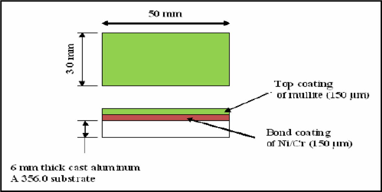
In the recent years, use of Yittia Stablised Zirconia, Mullite and Mullite Stablised Zirconia as TBC coatings for Al- Si alloy pistons. It has been observed that Mullite based TBC coatings are reliable and economical. The Mullite coatings directly on Al-Si alloy base causes crack propagation. The vast difference in coefficient of thermal expansion between Mullite coatings (α2 = 4.5 ´ 10-6 K-1) and Al alloy (α1 = 8.2 ´ 10-6 K-1) causes glassy phases at joining phase which causes cracking during thermal aging [14-19]. The use of a NiCr bond coat (of <150 μm) between the top coat and the Aluminum substrate reduces the crack propogation [10, 20]. It has been reported that the bond coat supports in improving the corrosion resistance and improves adhesion at higher operating temperatures. The bond coat additionally reduces the thermal stress arising between the bond caot and the substrate during operation [3, 21-24]. It has been reported that 3Al2O3:2Sio2 – La2O3 plasma sprayed, T6 treated Aluminum substrate with NiCr bond coat exhibited 1.6 times hardened and 1.2 times adhesion strength values when compared with ZrO2 coatings [20].
Alternatively, the use of NiCr between Mullite and Al base reduces the coating performance [7, 8]. In this research article, A356 Al alloy substrate is thermal sprayed with MiCr intermittent coating of 150 µm thickness and over coat of Mullite – ZrO2 (MZ) / Mullite – La2O3 (ML) of 150 µm thickness. The ML and MZ coated substrate is tested for its tensile and adhesion strength and compared. The best performing coatings were selected for numerical analysis on aluminium piston crowns using Ansys software.
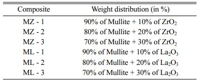
In this research article, double layered coatings of NiCr intermittent bond coating of 150 µm thick and over coat of Mullite – ZrO2 (MZ) and Mullite - La2O3 (ML) coatings 150 µm thick on A356 aluminium alloy treated to T6 condition using thermal plasma spraying was produced. The Mullite – ZrO2 (MZ) and Mullite - La2O3 (ML) were mixed with mullite at 10%, 20% and 30% by weight and thermal spray coated on A356 Aluminium alloy substrate. The double layered MZ / ML substrates after coatings were subjected for tensile strength testing using UTM of 200 KN capacity in accordance with ISO-527; and adhesive strength was carried out on UTM as per ASTM C 633-01 standards. The tensile test and adhesive test results were compared and the best performing MZ and ML composite coatings are selected for evaluation of residual thermal stress using numerical method study in Ansys.
Substrate Preparation
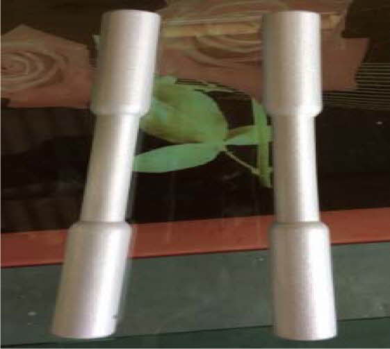
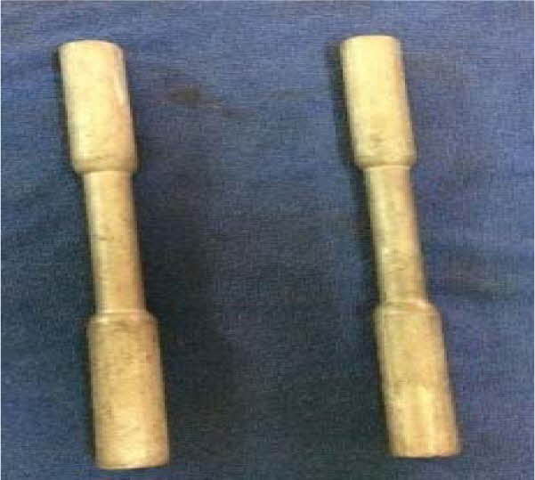
Aluminium A356 billets are selected for substrate preparation. The billets are melted using induction furnace and cast in die moulds to required size. The samples is quenched and allowed to age harden upto T6 condition. The samples are then cut into required shapes for adhesion a tensile study as specified in standards. The substrate surfaces were prepared to a roughness value of 100 μm for coatings using 20 μm alumina grits, at 0.5 Kg/min, at perpendicular to surface with an air pressure of 45 pounds per square inch at 100 mm stand-off distance [9]. The substrates were preheated for better adhesion at 300 oC using induction furnace for 1 hr [25, 26]. Two types of substrates were prepared a. 6 samples for tensile testing per ISO 1608 standard, b. 6 samples of 25.4 mm diameter and 50 mm length were prepared for adhesion test (as shown in Figs. 1 to 3). Fig. 2
Coating Preparation
In this research article, industrial grade NiCr, Zirconium oxide, Lanthanum oxide, Al and Si were used for preparing MZ and ML coat on A356 Al alloy substrates. The composition preparation table for over coat is listed in Table 1. The intermittent coat for bonding is prepared at 80% Nickel: 20% Chromium of alloy number – 43VF with particle size of 325 µm. The alloy has excellent resistance to tribological properties – wear and oxidation upto 1,000 oC.
Plasma Process
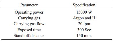
The plasma spray coating of NiCr intermittent bond coat – 150 µm thick and over coat of Mullite – ZrO2 and Mullite - La2O3 coatings 150 µm thick on A356 aluminium alloy was processed using 15kW plasma torch. The plasma spraying parameters are listed in Table 2 [27].
|
Fig. 1 Tensile bars before coating. |
|
Fig. 2 Tensile bars after coatings |
|
Fig. 3 Schematic diagram showing bilayered coated bars. |
Tensile Strength Test
The results of tensile test performed as per ISO – 1608 of the double layered MZ and ML coated specimen are listed in Table 3. The tests were performed to determine the improvement in the tensile of the MZ and ML coated with uncoated test bars. It is commonly reported that ceramic materials has poor tensile strength and good compression strength. e.g. alumina has tensile and compressive value of 1,100 MPa and 2,400 MPa respectively. The results of MZ/ML coated specimen confirms better in the tensile strength.
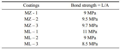
Adhesive Strength Test
The MZ and ML coatings are coated on the top surface of cast Al bars of 25.4 mm diameter and 50 mm height. The coated surface is glued using adhesive and cured in an oven at 170 ± 6 oC for 90 min. The cured samples were tested in UTM machine and the results of the adhesive strength of MZ and ML double layered coatings determined as per ASTM C633-79 are shown in Table 4. The adhesive strength results of MZ coatings were incremental when the % of ZrO2 is increased from 10% to 30%. The inter-granular coarsening of ZrO2 grains is decreased as the Al2O3 % is increased. It is because the Al2O3 content restrain and impede the growth of ZrO2 is reported to be the reason [28-30]. The results of ML coatings were decrementing as the La2O3 is increased in weight. The formation of glassy phase at the boundary is reported to be the reason [20, 30].
Salt Spray Test
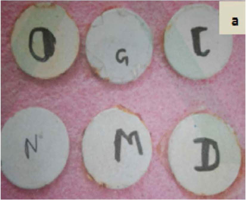
The MZ and ML coated and uncoated specimen samples of 1” diameter were subjected to corrosion test as per ASTMB117 using environmental chamber (make: ASCOTT CCT – 2000IP). The operating conditions of the environmental chamber are temperature at 35 oC, Sodium chloride of pH value 6.7, pressure at 15 psi, atomizer spray at 1.5 mL/hr. The specimens were tested continuously for 100 hrs. The samples after testing were evaluated using optical microscope (Fig. 4). It has been observed that due to the presence of ceramic coatings the formation of oxides or infiltration in the specimen were not evident [31-33].
Micro-hardness Test
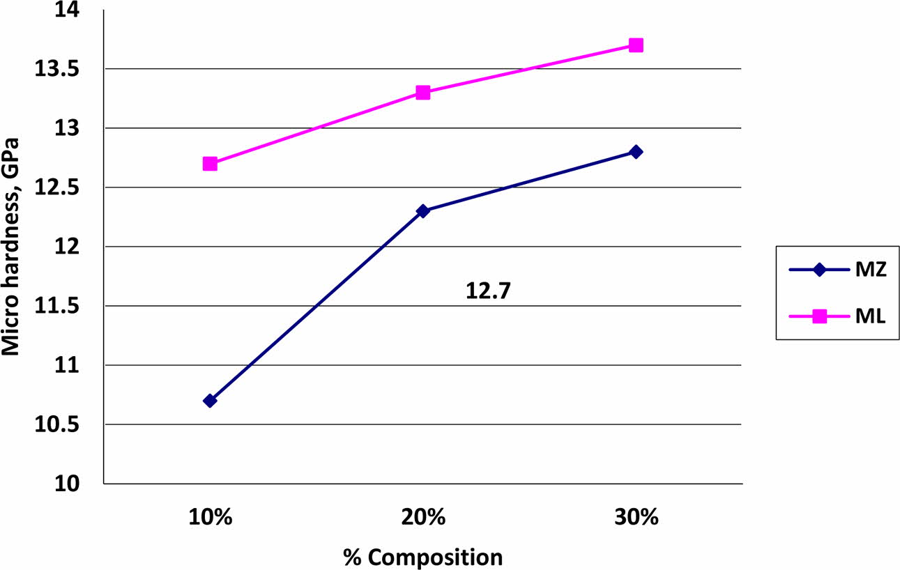
The hardness values of the MZ and ML coated specimen were evaluated as per IS 1501:13 using Micro Vickers indenter (make: Wolpert, Germany) and represented in Fig. 5. The average hardness values of MZ and ML coatings with NiCr bond coat values were observed to be at 10.7 to 12.8 GPa and 12.7 to 13.7 GPa respectively. The hardness values of ML coatings were 8% more than the traditional MZ coatings [34, 35]. The improvement in the hardness values is a clear indication that the solidification and dense coating formation [36-38].
Thermal Analysis
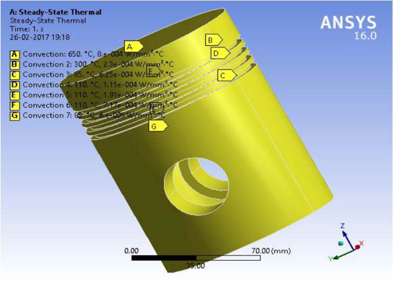
A model is being developed for thermal analysis in Ansys software with intermittent NiCr and ML over coat. The thermal analysis is carried for determining the Heat transfer rate and followed by structural analysis. The Aluminium alloy piston used in Kirloskar DM10 single cylinder water-cooled four stroke direct injection engine piston is modelled in Ansys workbench. The ML1 coating is selected as the best performing composite as per the results from Table 3 and 4. The piston crown is modelled in thermal environment with intermittent coat of NiCr (150 μm) and over coat of ML (150 μm). The model of the piston is shown in Fig. 6.
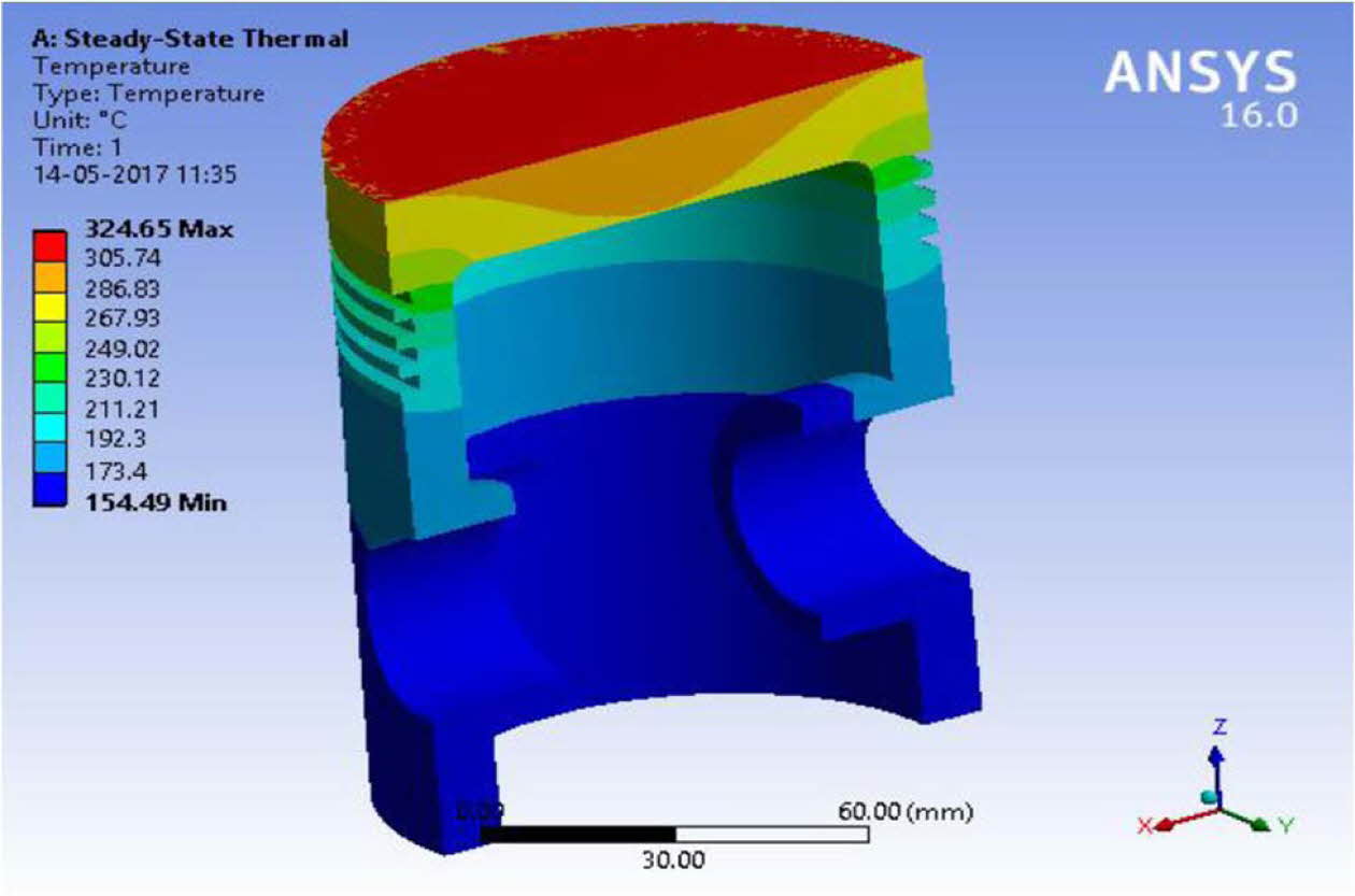
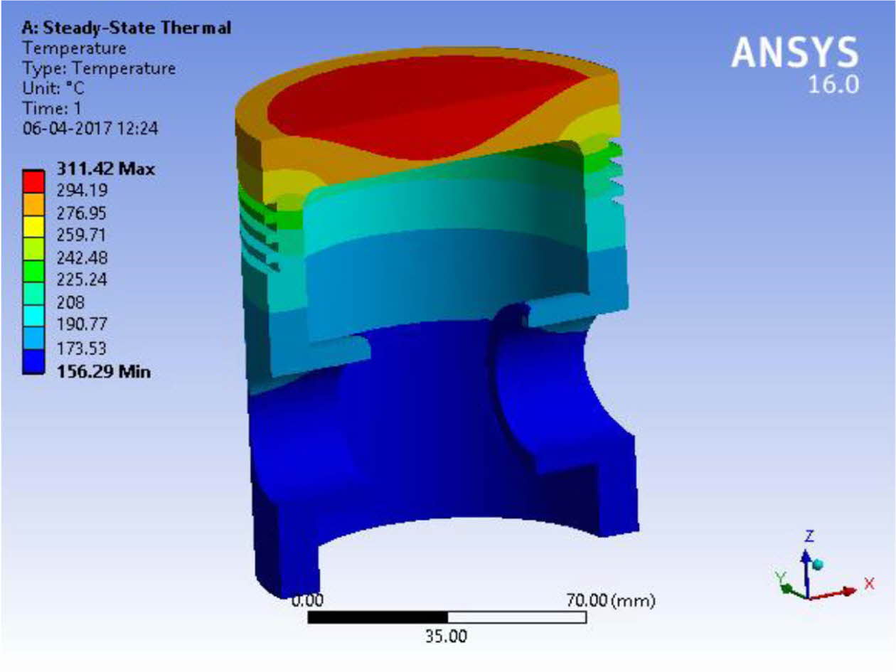
The heat transfer coefficient 800 ´ 10-6 and the combustion temperature 650 oC were obtained from literature reported [30, 39]. The temperature at piston crown arising as a result of convective heat transfer is around 250o C and at the piston base is lesser by 50 oC [40-41]. The heat transfer study of double layered NiCr intermittent coat and ML1 over coatings on Al alloy piston are compared with uncoated pistons. The results are shown in Table 5 and Figs. 6 to 8. Fig. 7
|
Fig. 4 ML and MZ Test specimens after salt spray test for 100 hrs (O as MZ1, G as MZ2, C as MZ3 and N as ML1, M as ML2 and D as ML3 coatings). |
|
Fig. 5 Micro hardness values of MZ and ML coated test specimens. |
|
Fig. 6 FEM model of Aluminium alloy piston. |
|
Fig. 7 Thermal stress of uncoated Aluminium alloy piston. |
|
Fig. 8 Thermal stress analysis of ML1 coated Aluminium alloy piston. |
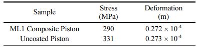
The numerical thermal stress analysis results of ML1 coated piston are lower than the uncoated pistons in terms of the deformation and residual stress values. The deformation arising due to residual stresses during operation is lower for ML1 coatings in comparison with uncoated pistons. The coupled analysis, confirms that ML1 coated double layered TBC helps to increase the operating temperature of the piston.
- 1. R. Prasad and N.K. Samria, Int. J. Mech. Sci. 31[10] (1989) 765-777.
-

- 2. R. Prasad and N.K. Sharma, Int. J. Mech. Sci. 33 (1991) 179-195.
-
- 3. M. Cerit, Surf. Coat. Technol. 205 (2011) 3499-3505.
-
- 4. A. Hultqvist, M. Christensen, and B. Johansson, SAE Technical Paper. 01 (2000) 1833:13.
-
- 5. D. Daniel, SAE Technical Paper. 890292:14.
-
- 6. M.M.S. Wahsh, R.M. Khattab, and M. Awaad, Adv. Mater. Res-Switz. 41(2012) 31-36.
-
- 7. M. Yasuoka, K. Hirao, M.E. Brito, and S. Kanzaki. J. Am. Ceram. Soc. 78[7] (1995) 1853-56.
-
- 8. P. Bridjesh and G. Rajendra Prasad. IJSRES, 1[4] 2014.
- 9. M.F. Bahbou, P. Nylen, and J. Wigren. J. Therm. Spray. Techn. 13 (2003) 508-514.
-
- 10. B. Shreeram, I. Rajendran, E. Ranjith Kumar 28[6] (2018) 2484-2493.
-
- 11. K.V. Kannan Nithin, N. Surriyanarayanan, and A. Sola, J. Non oxide Glasses. 2 (2010) 23-34.
- 12. N. Pandiaraj. B. Shreeram, and I. Rajendran, IJCPS. 4 (2015) 20-28.
- 13. S. Sathyamoorthi and M. Prabhakaran, S. Abraar, IJSEAS. 2[4] ( 2016) 258-263.
- 14. K.S. Mazdiyasni and L.M. Brown. J. Am. Ceram. Soc. 55[1] (1972) 548-552.
-
- 15. T. Takei, Y. Kameshima, A. Yasumori, and K. Okada, J. Am. Ceram. Soc. 82[10] (1999) 2876-2880.
-
- 16. B. Ghate, D.P.H. Hasselman, and R.M. Spriggs. J. Am. Ceram. Soc. Bull 52[9] (1973) 670-672.
- 17. M. Ibrahim, S.M. Naga, Z.A. Kader, and E.A. Salam. Ceram. Int.21 (1995) 265-269.
-
- 18. X.C. Zhong and G.C. Sun. Fifth biennial worldwide congress. Refractories— A Worldwide Technology, New Orleans. 2 (1997) 943-952.
- 19. T. Sato, M. Shizuka, and M. Shimada. Ceram. Int. 12[2] (1986) 61-65.
-
- 20. B. Shreeram and I. Rajendran. Int. J. of Heavy Veh. Syst. 25[3] (2017) 406-418.
-
- 21. T.M. Yonushonis, J. Therm. Spray Technol. 6 (1997) 50-56.
-
- 22. E. Buyukkaya, Surf. Coat. Technol. 202 (2008) 3856-3865.
-
- 23. E. Buyukkaya and M. Cerit Surf. Coat. Technol. 202 (2007) 398-402.
-
- 24. H.W. Ng and Z.Gan Finite Elem. Anal. Des. 41 (2005) 1235-1254
-
- 25. S. Sathish and M. Geetha. Trans. Nonferrous Met. Soc. Chin. 26 (2016) 1336-1344.
-
- 26. S. P. Sahu, A. Satapathy, A. Patnaik, K.P. Sreekumar, P.V. Ananthapadmanabhan, Materials and Design.31 (2010) 1165-1173.
-
- 27. S. Yugeswaran, V. Selvarajan, M. Vijay, P.V. Ananthapadmanabhan, and K.P. Sreekumar, Ceram. Int. 36 (2010) 141-149.
-
- 28. E .M.M. Ewais, D. Hussien A. Besisa, Z. I. Zaki, A. El and H.T. Kandil, J. Am. Ceram. Soc. 32 (2012) 1561-1573.
-
- 29. H. Ji, M. Fang, Z. Huang, K. Chen, Y. Xu, Y. Liu, and J. Huang, Ceram. Int. 39 (2013) 6841-6846.
-
- 30. P. Ramaswamy, Int. Conf. on adv. in surf. Trtmt. Research and appli. 6 (2003) 654-659.
- 31. M. Saremi, A. Afrasiabi, and A. Kobayashi, Surf. Coat. Technol. 202 (2008) 3233-3238.
-
- 32. R. Gören and C. Özgür. J. Ceram. Process Res. 13[3] (2012) 262-266
- 33. I.J. Kim and J.L. Gauckler. J. Ceram. Process Res. 9[3] (2008) 240-245.
- 34. P. Kumar, M. Nath, A. Ghosh and H.S. Tripathi, Mater. Charact.101 (2015) 34-39.
-
- 35. C. Cortés-Escobedo, A.M. Bolarín-Miró, F. Sánchez-De Jesús, B. Portales-Martíneza and A.L. Vázquez-Díaz. J. Ceram. Process Res. 13[4] (2012) 457-460.
- 36. Y. Li and K.A. Khor, Surf. Coat. Technol. 150(2-3), 125-132 (2002)
-
- 37. W. Lee, J. Zhang, H. Che, T. Sekino, and S.H. Kim. J. Ceram. Process Res. 9[6] (2008) 553-556.
- 38. X. Zheng, J. Shi, X. Liu and C. Ding, J. Ceram. Process Res. 2[4] (2001)174-179.
- 39. I. Kucuk and T. Boyraz, J. Ceram. Process Res. 20[1] (2019) 73-79.
- 40. K.N. Pandiyaraj, R.R. Deshmukh, B. Shreeram, and R. Mahendiran. J. Nano Sci. Nano Technol. 2[1] (2014) 436-441.
- 41. S. Bakthavathsalam, R.I. Gounder, and K. Muniappan. Environ. Sci. Pollut. R. 26 (2019) 24772-24794.
-
 This Article
-
2022; 23(3): 263-267
Published on Jun 30, 2022
- 10.36410/jcpr.2022.23.3.263
- Received on Nov 2, 2021
- Revised on Nov 27, 2021
- Accepted on Nov 29, 2021
Services
- Abstract
introduction
experimental work
materials and methods
results and discussion
conclusion
- References
- Full Text PDF
Shared
Correspondence to
- B. Shreeram
-
Department of Mechanical Engineering, Dr. N.G.P. Institute of Technology, Coimbatore, Tamilnadu, India
Tel : +91- 97909 35543 - E-mail: shreesotbk@gmail.com
Clean-Energy Research Institute(CRI), Hanyang University, 222, Wangsimni-ro, Seongdong-gu, Seoul, 04763, Korea
E-mail: jcpr@hanyang.ac.kr