


- A review on the effects of ceramic sand particles on most casting defects
Malek Alia,*, Abderraouf Gherissb, Anwar H. Al-Assafa and Mohammad Ismailc
aAircraft Maintenance Dept., Faculty of Aviation Sciences, Amman Arab University, Jordan
bMechanical Engineering Dept., Faculty of Engineering, University of Tabuk, KSA
cRenewable Energy Engineering Dept., Faculty of Engineering, Amman Arab University, JordanThis article is an open access article distributed under the terms of the Creative Commons Attribution Non-Commercial License (http://creativecommons.org/licenses/by-nc/4.0) which permits unrestricted non-commercial use, distribution, and reproduction in any medium, provided the original work is properly cited.
Sand particles featuring great refractoriness, chemical stability, strength, and high permeability, which are monitored at high temperature, are the most common utilized material for shape making. In casting process, the material is first liquefied by heating and then poured into a priori prepared mold cavity where casting is solidified. The cast is then taken out, cleaned, and formulated to the desired shape. In general, there are different types of casting defects such as surface, internal, and visible defects. However, the shapes and properties of sand particles have a great effect on the quality of casted parts. Nevertheless, other critical factors contribute to the causes of defects such as design of mold, pattern, and core, in addition to metal composition, melting, pouring, and gating system. In this paper, the effects of ceramic sand particles on most casting defects are reviewed and discussed in details
Keywords: sand particles, sand properties, casting defects
Sand mold is traditionally fabricated by withdrawing a pattern from the sand mixture that is packed around it [1]. It should be noted that suitable sand properties are required for good casting quality. Sand casting is the most frequently utilized for making complex shapes in comparison with other shaping strategies [2]. There are many different metals that are used in metal casting such as iron, pure aluminum, pure copper, nickel, lead, zinc, and titanium. However, alloys are usually utilized more than other pure metals in basic applications. Sometimes, some non-metallic materials are utilized in casting processes such as Al-TiC composites. Such composites can be fabricated through melting the aluminum at 850°C and then adding TiC gradually. The molten Al-TiC is then poured to sand mold cavity [3, 4]. Titanium Carbides have been synthesized directly from mixtures of titanium oxide and graphite at high temperatures [5]. Composites can also be formed by sand casting and powder metallurgy processes such as Al-12Si and Al-SiO2 [6]. In [7], the Al-SiO2 composites, the reinforcements of SiO2 were added gradually to the molten aluminum with different weight ratios where the mixture was poured into a priori prepared sand mold.
Casting defects are an undesired abnormality in a metal casting. Blow, scars, drop, scab, penetration, dirt, wash, sand inclusion, misrun, buckle, cold shut, shrinkage, and hot tear can be classified to be either surface, internal, or visible defects [8, 9]. Generally, the defects are caused by one or more of the following reasons: (i) sand properties, (ii) improper pattern, (iii) improper mold, (iv) improper metal composition, (v) defects in preparation of molds and/or patterns, (vi) inappropriate pouring by feed rate, and (vii) improper gating and/or lacking melting temp [10-12]. Numerous factories try to avoid the aforementioned causes of defects in their casting process in order to improve quality and efficiency. However, despite of the numerous research that has been conducted on casting defects, the focus in the review will be on the effect of ceramic sand particles properties on the most common casting defects and remedies.
Natural sand is abundant, low cost, and contains more than 80% of SiO2 [13]. Therefore, SiO2 with great thermal stability is suitable for use in sand molds. Refractory clay binder is required for sand forming to achieve acceptable degree of plasticity and strength after drying. Many Additives (e.g., dust, wood flour, and coal) can be used in molding sand to improve specific properties [10, 14]. The cycle of sand molding starts with preparing a temporary sand mold for each new casting and then formed by filling it around the pattern in both halves of the mold where the pattern is an exact copy of the outside casting shape [2]. After removing the pattern, the cavity required for the casting process is formed. In general, forming the sand mold includes placing the pattern, packing the sand, and removing the pattern. The mold-making is affected by the size of the casted part, the number of cores, and the type of sand mold. The lubricant is necessary for covering the pattern and mold cavity to facilitate removal of the pattern and casting from the sand. Lubricant is also used in order to improve the flow of the metal and to improve the casting surface [2]. Generally after preparing mold halves, they are sealed and clamped together. To reduce casting defect, the mold halves must remain sealed. Sufficient molten metal can be poured manually to fill in the cavity.
To avoid casting defects, many variables must be taken into consideration in the casting process such as ambient temperature, casting temperature, time, and rate, in addition to many other factors that will be discussed in this paper. When the entire cavity is filled in and the molten metal solidifies, the final shape of the casting is formed. However, the cooling process may lead to shrinkage and/or some cracks due to quick solidification. Finally, after the completion of solidification, sand mold can simply be broken and then the casting can be removed [8].
Permeability
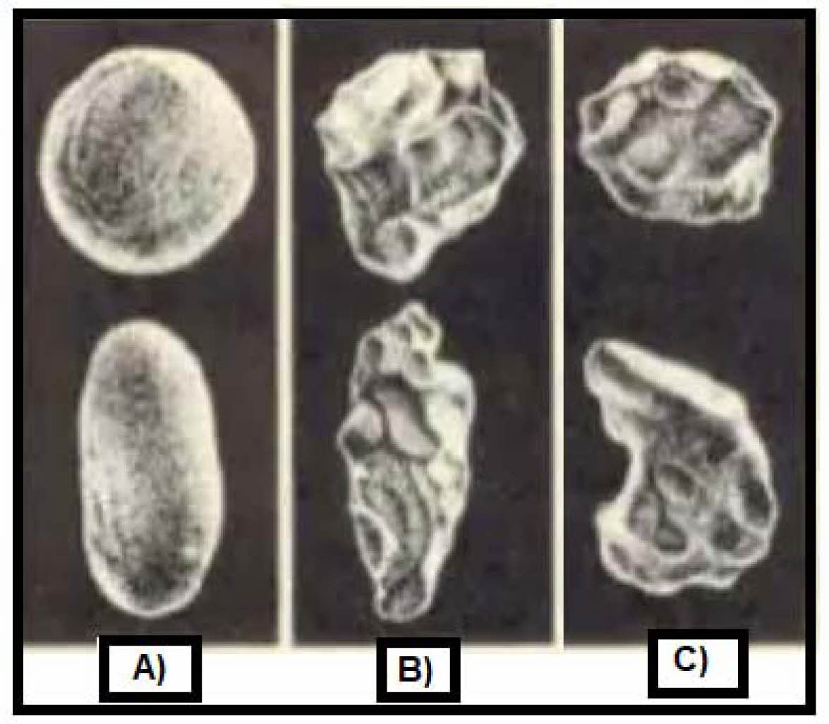
Permeability is the passage measure of liquids and gases through a material. Molten metal always contains some dissolved gases that are produced from stirring speed. If the dissolved gases are not allowed to escape, the gases can form holes and pores [15]. Casting defects can be avoided if these gases are allowed to escape by suitable sand permeability degree. There are three types of porosities: (i) non-porous, (ii) porous with unconnected pore spaces, and (iii) porous with connected pore space. Sand permeability and pouring temperatures have a critical impact on the cast properties (i.e., strength and hardness). To obtain high-permeability mold, the size of used sand particles in mold should be made of sand with a size from 75 mm (i.e., fine sand) to 300 mm (i.e., coarse sand). A mixture of 80 ratio of coarse sand and 20 ratio of fine sand can certainly allow the trapped air bubbles and gases to escape easily from mold [16]. The permeability of sand mold greatly affects the hardness, porosity, and strength of products. In general, the porosities in casted products are considered a defect. On the other hand, this porosity is considered as an advantage in shaped porous metals. In addition, sand permeability in mold can be influenced by the amount of water contents, sufficient drying, and low compaction that lead to retaining moisture [17, 18]. The grain shape has also an effect on the casted samples. Generally, three sand types are used in sand mold (refer to Fig. 1). The first type (i.e., rounded sand) gives insufficient bonding strength, which is caused due to a reduction in mold cohesion. However, it causes a smooth flow of the molten metal and a smooth surface of the products. The second type (i.e., angular sand) has a sufficient bonding because of the interlocking between sand particles. However, poor flowability and permeability with rough surface of the products can be obtained. As for the third type (i.e., sub-angular sand), it shows a better strength with lower permeability in comparison with rounded grains, whereas the sub-angular grains shows a better permeability with lower strength in comparison with the angular grains [19].
Cohesiveness
The strength of the molding sand (i.e., cohesiveness) is the ability of sand particles to stick together [19]. Sand strength or cohesiveness depends on (i) grain size and shape, (ii) mixture of various-size grains, (iii) bonding content and its distribution, and (iv) moisture content. The clay helps sand bonding but sharp sand are not easily bonded. Sand particles are also held together through homogeneous coating of starting powders with an inorganic binder [20]. The mixture of various angular sand particles with inorganic binder gives a better cohesiveness than rounded sand particles. Binders are actually added to molding sand to increase cohesion and strength that lead to retain mold and cavity shapes. On the other hand, adding binders reduces refractoriness, and causes some defects such as blow hole, low dimensional stability, and/or unexpected microstructure due to the decomposition of organic binder at height temperatures [21]. Bentonite, Fireclay, Kaolinite, Illite, and Limonite are the most important binders that can be added to sand during molds fabrication. In addition, strength and cohesiveness depends on the moisture content. Around 2-8% of moisture should be added to the mixture of clay and silica sand to create strong bonds. As a result of filling the spaces between the grains of sand by clay and moisture, the permeability decreases. On the other hand, increasing the clay content increases the green compressive strength [22]. Molding sand must have a good cohesiveness. Lack of cohesiveness leads to loss the shape of the mold cavity and leads to the mold collapse or partial destruction during conveying and turning over. During the filling of mold by molten metal, the a priori prepared cavity (i.e., bottom and walls) will be subjected to high pressure. Hence, the sand should be strong enough to support this pressure. The metal weight, when pouring into the cavity with a very high sand permeability, leads to the metal penetration into the inner surface of the mold. As a result, the casted part becomes very rough especially in the lower side [23, 24].
Plasticity
Plasticity of solid materials is the ability of solids to change their shape permanently without rupture when subjected to certain stresses. This shape change is known as permanent deformation. Sand plasticity is the ability of the sand to get compacted and behave like a fluid. In general, plasticity or flowability increases with a decrease in the green strength and grain size of sand. The plasticity also varies with moisture and clay content in sand. To obtain a good impression on the mold from the patterns, adequate plasticity is needed [8]. Therefore, appropriate green strength and grain size of sand with appropriate moisture and clay content are needed to obtain a good impression and to increase the chances of getting products with fewer defects [25, 26].
Collapsibility
Collapsibility of molding sand is very important for sand reclamation process and surface finish. Collapsibility can be assessed through determination of the time to fail under constant load. There is a minimum acceptable collapsibility degree for sand mold. This means that the mold responds to the shrinkage of the cast due to the metal shrinkage during freezing and subsequent cooling [25]. The shrinkage defect in the casted product is also due to the poor flowability of molten metal and the thickness [21]. Lack of collapsibility in the molding sand may lead to cracks in the casting. Straw can be added to the core or the hollow core to enhance collapsibility [27].
Refractoriness
The grains of the molding sand should not melt, soften, or sinter under the action of high temperatures when the molten metal is poured into the mold [27]. This property is called refractoriness. Silica sand is often used in molds fabrication because (i) it has a great refractory at very high temperatures, (ii) it is easily molded into complex shapes, (iii) it has adequate porosity and it permits an easy escape of gasses created by liquid metal, (iv) it can be utilized many times for making molds after addition of a few bonding materials, and (v) it is cheap, available, and has a high coefficient of thermal expansion [28]. Refractoriness and other important characteristics of molding sand and can be increased to a limited extent. Poor refractoriness may cause a rough casting surface due to sand burning. High purity of silica sand with a minimum addition of binder can be considered as an ideal mixture [29, 30]. When the sand of the mold contains coarse particle sizes and an appropriate amount of SiO2, the degree of refractoriness of sand increases [31]. Refractoriness value can be determined from the sintering point and not from the melting point of the sand. The organic materials that are present in the sand affect the sand thermal resistance (i.e., refractoriness) during the casting of the metal and alloys, especially if it is in large quantities [32]. Generally, any lack of properties required for molding sand will lead to various defects.
|
Fig. 1 Grain sand shapes categories: (A) rounded sand, (B) angular sand, and (C) sub-angular sand. |
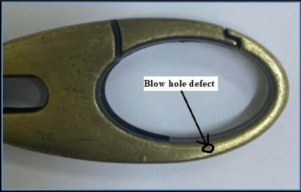
Blow hole defect
Blow holes, as shown in Fig. 2, are types of internal defects that include very small internal cavities. Blow holes can only be seen after machining or by heavy shot blasting. The blow holes are, in fact, smooth walled isolated cavities. Bubbles or holes are formed by trapping gases during pouring and solidification. When pouring molten metal into the wet sand mold, large amounts of gases will be generated. With poor ventilation, they will remain inside the casting as defects in the upper part of the mold [33- 35]. The blow hole defect can be reduced or eliminated by the controlled moisture content, volatile components, permeability, and ventilation of mold [36].
Scar defect
Scars, as shown in Fig. 3, are surface defects and occur due to inappropriate permeability of sand. The scar appears at the surface and also directly below the surface of casting in large numbers together. The scar defect is obvious to the eye and do not require equipment to identify. It can be prevented by maintaining the pouring temperature at appropriate levels [37].
Drop defect
Sand drops are a visible casting defect that are caused by pieces of metals or sand particles’ drops into the liquid metal [38]. They are an irregularly shaped sand holes on the surface of casting [29]. Sand with low green compressive strength, less amount of binders, soft ramming, insufficient fluxing of molten metal, high metal flow rate, pressurized gating system, formation of oxides from the reaction between molten metal and air, high temperature of metal, and improper cleaning of the mold lead to casting drop defects. Drop defects can be avoided by increasing sand mold strength, adding reinforcements to sand, avoiding stirring that causes the thermite reaction and oxidation [39-41].
Scab defect
Scabs are visible and/or internal defects and they are lean layers of metal projecting over the casting surface over other lean layers of sand. This type of defects occurs when sand moves from the upper surface of the mold and gets replaced by the molten metal as an internal layer [42]. Fine and low permeability sand in addition to the high moisture content of sand lead to dirt defects. Reducing the moisture content of the molding sand is one way to treat such defects, which increases the overall mold strength, reduces the amount of sand expansion, and lowers the temperature of the molding sand to increase its strength properties [35, 29, 43].
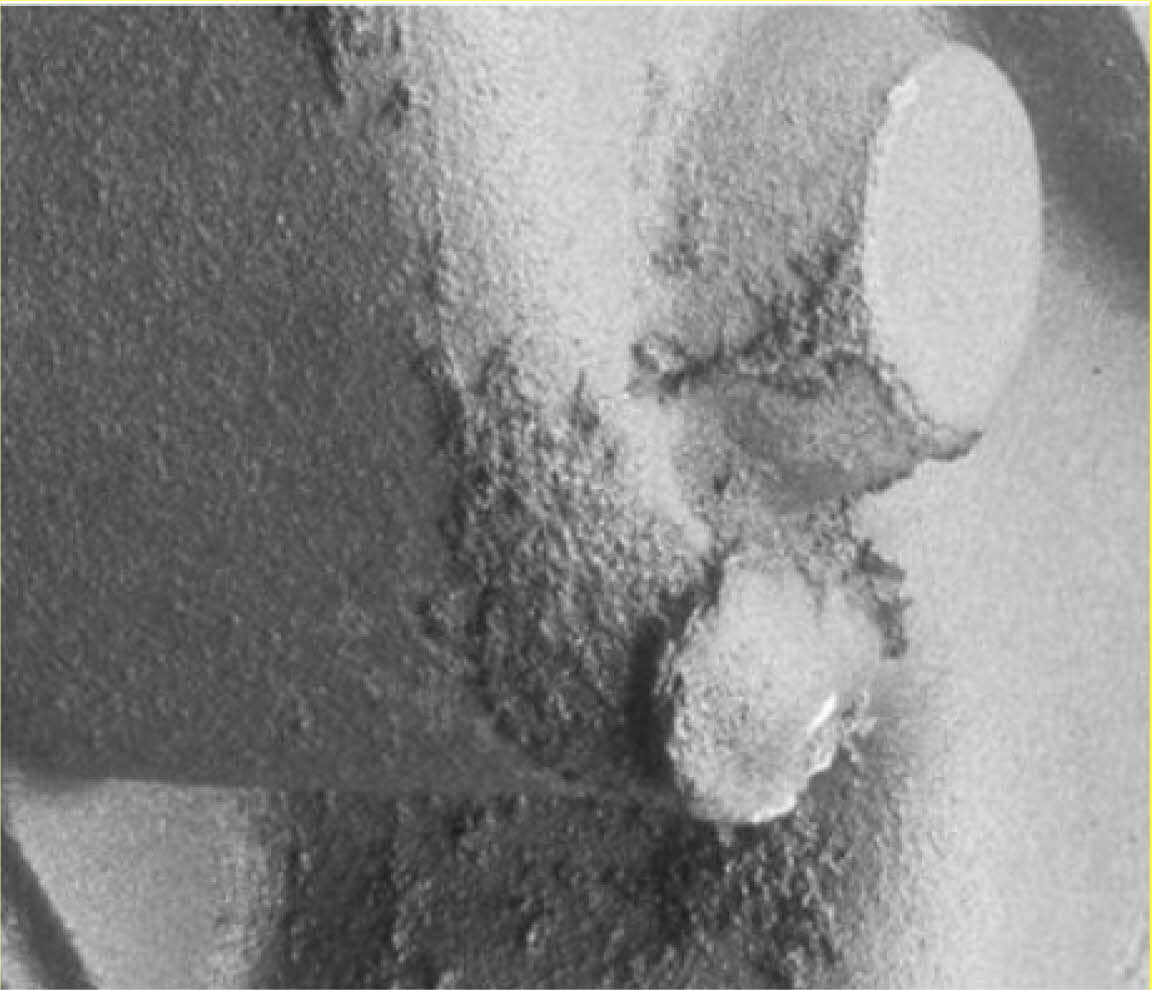
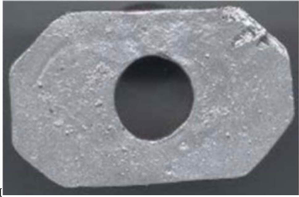
Metal penetration defect
Liquid metal flows between the sand particles when the mold surface is too soft and porous. Insufficient coal dust and coating, large sand grain size, low strength of mold sand and core, and unsuitable pouring temperature lead to penetration defects as shown in Fig. 4. In addition, sand burning may cause metal penetration as well [44].Penetration defects can be avoided by using fine sand grain size and by providing hard ramming. When the sand is subjected to high temperature, the bentonite and silicate components can be sintered. Formation of iron silicate, as a result of the reaction of iron oxides with silicates of low melting point, decreases sinter point of the sand. If impurities are sintering and melting in the molding sand, the molten metals penetrate faster [45].
Dirt defect
Dirt defects are surface and/or visible defects where sand particles get embedded in the top surface that causes rough cavities and pits in the casting surface before cleaning. Sand grains may be seen visually or under magnification (refer to Fig. 5). To avoid such a defect, appropriate compression strength of sand and regular cleaning of die should be maintained, pattern should have little parts as much as possible in the cope, clean and pour molten metal should be used, liner height should be adjusted to reduce pressure at the drag/cope mold cavity edges, proper pattern condition should be ensured, and manual handling of closed mold should be avoided [29,40].
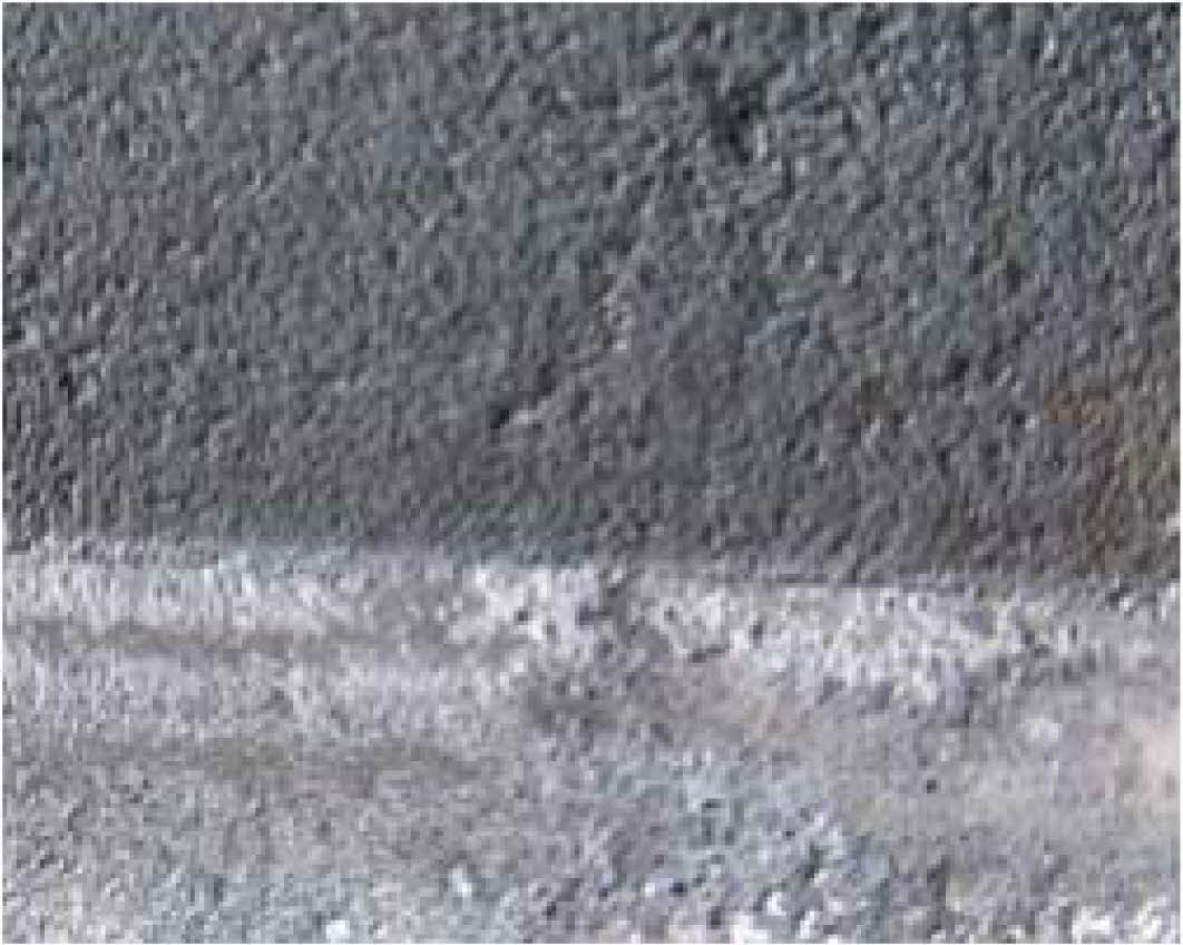
Wash defect
During the pouring of molten metal, erosion occurs and this leads to irregularities on the surface that is facing the molten metal flow. High velocity jet of liquid metal in the bottom gate allows too much metal to flow through it. Low strength of mold and core lead to wash defect as shown in Fig. 6. To improve gating system, more binders and reinforcement are required for mold sand to prevent wash defects [29, 46, 47].
Sand inclusion defect
Sand inclusion is also known as sand hole as shown in Fig. 7. It occurs when the sand grains remain in the casting after solidification [48]. Sand inclusion is formed by the metal flow and thermos-mechanical stresses. Shear stresses and compressive acting on the mold may lead to erosions. It is difficult to diagnose such defects because they are irregularly formed and also spread in different locations. Sand particles often float on the surface of the casting due to the different densities between the metal and the sand. Defects become visible only during machining, because sand impurities are under the surface of the casting. General possible causes of sand inclusions are low core strength, high pouring rate, erosion, and pouring time [10, 12, 46].
|
Fig. 2 Blow hole defect. |

|
Fig. 3 Scars and pinholes. |
|
Fig. 4 Metal penetration defect. |
|
Fig. 5 Dirt defects |
|
Fig. 6 Wash defect. |

|
Fig. 7 Sand inclusions defect |
Sand particles’ shapes and properties affect most casting defects such as blow hole, scar, drop, scab, metal penetration, dirt, wash, and sand inclusion. Sand particles in mold with good properties contribute to avoiding or minimizing the casting defects. Other critical factors that may contribute to defects occurrence are: design of mold, pattern, and core in addition to metal composition, melting, pouring, and gating system. Common remedies for casting defects, which are caused by sand particles’ shapes and properties, include using proper cores with correct arrangements, adequate sand permeability, proper venting, controlled content of moisture and volatile constituents in the sand, lowering the pouring temperature of the metal, lowering the temperature of the molding sand, maintaining correct green strength of sand mold, providing sufficient reinforcement and binders to sand, avoiding a long-time stirring, optimal range of pouring height, proper pouring time, regular cleaning of die, small patterns in the cope, adjusting liner height to reduce pressure at the drag/cope mold cavity edges, ensuring proper pattern condition, and avoiding manual handling of closed mold.
- 1. T. Sivarupan, N. Balasubramani, P. Saxena, D. Nagarajan, M. El Mansori, K. Salonitis, M. Jolly, and M. Dargusch, J. Add. Manu. 40 (2021) 101889.
-

- 2. E. Paul, J.T. Black, and R.A. Kohser, “Materials and Processes in Manufacturing” (John Wiley & Sons, Inc, 2003) p.31.
- 3. H. Pal, N. Jit, A.K. Tyagi, and S. Sidhu, Adv. Appl. Sci. Res. 2[5] (2011) 360-371.
- 4. A. Gherissi and M. Ali, Epit. J. Silic. Bas. Comp. Mate. 72[1] (2020) 25-29.
-
- 5. M. Ali and Z. Muayaduldeen, J. Ceram. Process. Res. 16[5] (2015) 1-5.
- 6. A. Samer, M. Ali, P. Basu, and F. Ahmad, J. Eng. Mech. 140[6] (2014) 04014030-1-7.
-
- 7. M. Ali and G. Abderraouf, J. Ceram. Process. Res. 20[3] (2019) 259-263.
- 8. S. Kalpakjian and S.R. Schmid “Manufacturing, Engineering & Technology” (Pearson Education, 2006).
- 9. W. Ali, Inte. Res. J. Eng. Tech. 7[1] (2020) 878-891.
- 10. B.S. Kamble, Int. J. Inno. Res. Sci. 5[2] (2016) 1281- 1288.
- 11. A. Juriani, J. Mech. Civil Eng. 12[6] (2015) 43-54.
- 12. V. Ingle, and M. Sorte, J. Eng. Res. Appl. 7[3] (2017) 47-54.
-
- 13. C. Kaemkit, S. Niyomwas, and T. Chanadee, J. Ceram. Process. Res. 21[4] (2020) 460-464.
-
- 14. W.A. Ayoola, S. Adeosun, and A. Oyetunji, CIRP Ann. Manuf. Technol. (2013) 213-218.
- 15. M. Ali, J. Silicate Based and Composite Mate. 72[6] (2020) 198–204.
-
- 16. R.J. Fruehan, “Gases in metals” (ASM International, 1992).
- 17. O.O. Ajibola, D.T. Oloruntoba, and B.O. Adewuyi, Int. J. Meta. 2015 (2015) 1-13.
-
- 18. N.A. Ademoh, Int. J. Phys. Scie. 3[10] (2008) 240-244.
- 19. J. Zych, M. Wojcik, J. Kolczyk, and T. Snopkiewicz, J. Meta. Foun. Eng. 40[3] (2014) 191-202.
-
- 20. R.W. Cahn and P. Haasen, “Physical Metallurgy” (Elsevier, 1996).
-
- 21. E.H. Kim, G.H. Cho, H.Y. Park, H.H. Choi and Y.G. Jung, J. Ceram. Process. Res. 22[1] (2021) 1-7.
-
- 22. G.H. Cho, E.H. Kim, and Y.G. Jung, J. Korean Ceram. Soc. 53[5] (2016) 541-547.
-
- 23. H.S. Bawa “Manufacturing Processes-11” (Tata McGraw-Hill, 2004) p.25-29.
- 24. S.O. Seidu and B.J. Kutelu, J. Mine. Mate. Char. Eng. 2[5] (2014) 507-512.
-
- 25. C.A. Loto, J. Appl. Clay Sci. 5[3] (1990) 249-263.
-
- 26. S.R. Shah, J. Eng. Rese. Appl. 6[2] (2016) 32-38.
- 27. D.S. Deore, G.B. Chaudhari, A.G. Chaturvedi, and S.U. Gunjal, Int. J. Adv. Tech. Eng. Sci. 3[1] (2015) 1571-1580.
- 28. P. Beeley Met, “Foundry Technology” (University of leeds, 2001) p.480-487.
-
- 29. R.P. Gaikwad and P.A. Gaikwad, Int. J. Adv. Res. 4[11] (2016) 523-531.
-
- 30. S.P. Singh, A.P. Singh, and Y.R. Gautam, “Workshop Concept” (Orange Books Publication, 2021) p.57.
- 31. F.O. Edoziuno, R.O. Akaluzia, B.U. Odoni, and C.C. Nwaeju, Int. J. Res. Eng. Inno. 1[3] (2017) 225-229.
- 32. J.O. Aweda and Y.A. Jimoh, J. Rese. Infor. Civil Eng. 6[2] (2009) 68-77.
- 33. R. Rajkolhe and J.G. Khan, Int. J. Res. Adv. Technol. 2[3] (2014) 375-379.
- 34. M.R. Latte and P.D. Chougule, Int. J. Eng. Res. Tech. 10[1] (2017) 626-631.
- 35. A.S. Karapse, J. Emer. Tech. Inno. Res. 3[6] (2016) 94-98.
- 36. D.N. Shivappal, Int. J. Eng. Inve. 1[6] (2012) 01-05.
- 37. P. Bhatt and R. Singla, Int. J. Sci. Eng. Res. 8[12] (2017) 255-263.
- 38. V. Nerle and S. Shinde, Int. J. Eng. Res. Tech. 2[9] (2013) 2180-2188.
- 39. C.A. Loto and H. Adebayo, Appl. Clay Sci. 5[2] (1990) 165-181.
-
- 40. R.T. Patil, V.S. Metri, and S.S. Tambore, Int. J. Eng. Res. Tech. 4[11] (2015) 639-644.
-
- 41. M.I. Khan and S. Haque, “Manufacturing Science” (PHI, 2011) p.109-116.
- 42. S. Guharaja, A. Noorul Haq, and K.M. Karuppannan, Int. J. Adv. Manu. Tech. 30[8] (2006) 1040-1048.
-
- 43. A.M.S. Noohi, N. Hamidnezhad, A. Safikhani, M.R.G. Nia, and A. Modaresi. Int. J. Meta. Cast. 11 (2017) 347-355.
-
- 44. P.K. Ganguly and R. Rana, Int. J. Eng. Sci. Res. Tech. 7[7] (2018) 115-122.
- 45. A. Joshi and L.M. Jugulkar, Int. J. Mech. Prod. Eng. 2[4] (2014) 87-92.
- 46. S.S. Hiremath and S.R. Dulange, Int. J. Inno. Eng. Res. Tech. 2[9] (2015) 1-9.
- 47. N. Qosim, A. Mufarrih, A. Sai, A.H. Firdaus, F. Andika, R. Monasari, and Z.F. Emzain, J. Appl. Eng. Tech. Sci. 2[1] (2020) 1-6.
-
- 48. A.A. Gaware and A.K. Mahalle, Int. J. Innov. Eng. Sci. 2[5] (2017) 1-19.
 This Article
-
2022; 23(3): 257-262
Published on Jun 30, 2022
- 10.36410/jcpr.2022.23.3.257
- Received on Aug 8, 2021
- Revised on Oct 30, 2021
- Accepted on Nov 27, 2021
Services
- Abstract
introduction
raw materials and the process cycle for sand casting
properties required for molding sand
the effects of sand particles on most popular casting defects
conclusion
- References
- Full Text PDF
Shared
Correspondence to
- Malek Ali
-
Aircraft Maintenance Dept., Faculty of Aviation Sciences, Amman Arab University, Jordan
Tel : +00962790851286 Fax: +0096264791414 - E-mail: m.alsalem@aau.edu.jo
Clean-Energy Research Institute(CRI), Hanyang University, 222, Wangsimni-ro, Seongdong-gu, Seoul, 04763, Korea
E-mail: jcpr@hanyang.ac.kr