- The effect of ag-epoxy electrodes on the thermal and mechanical properties of multilayer ceramic capacitor
Chang Ho Lee and Jung Rag Yoon*
R&D Center, Samwha Capacitor, Yong-In, Korea
This article is an open access article distributed under the terms of the Creative Commons Attribution Non-Commercial License (http://creativecommons.org/licenses/by-nc/4.0) which permits unrestricted non-commercial use, distribution, and reproduction in any medium, provided the original work is properly cited.
The demand for reliable multilayer ceramic capacitors has significantly increased in automobile, aerospace, and 5G network industries. Therefore, the utilization of Ag-epoxy electrodes for the development of highly reliable MLCCs has become essential. In this study, the changes in mechanical and thermal stress caused due to the utilization of Ag-epoxy electrodes were analyzed using 3D finite element analysis. Subsequently, the reliability of the MLCC was evaluated using the board flex, thermal shock, and temperature-humidity-bias test. A comparison between the simulation results was performed and it was observed the bending resistance of the soft termination type multilayer ceramic capacitor with Ag-epoxy electrode was increased. Additionally, solder deterioration due to thermal shock was prevented, and it had excellent moisture resistance
Keywords: Multilayer ceramic capacitor, Finite element analysis, Soft termination, High reliability
Multilayer ceramic capacitor (MLCC) is a crucial com- ponent in the electronics industry because it can be used for applications such as noise reduction, DC blocking, filtering, and energy storage functions. Additionally, MLCCs are widely used in electronics products [1-3]. In particular, the electrical and industrial applications of MLCCs have been continuously increasing and it is crucial to develop highly reliable products that can continuously operate under harsh outdoor environments. The reliability of MLCCs might be affected due to improper handling (mechanical impact, bending, and vibration) or due to harsh environment (low temperature, high temperature and humidity) [4]. The cracks caused due to mechanical impact result in short circuit between the internal and external electrodes, and these phenomena increase the leakage current of the MLCC [5]. A recent trend is to develop soft-termination type MLCCs which consist of conductive resin electrodes to prevent the occurrence of cracks due to mechanical force and to suppress the MLCC deterioration due to temperature and humidity [6]. The structure of conventional MLCCs consists of three layers, and it is formed by directly plating Cu electrodes on both ends of the ceramic with Ni/Sn. However, in the case of soft-termination-type MLCC, the electrodes on both ends of the ceramic are composed of a conductive resin containing metal (Ag or Cu), and Ni/Sn plating is applied to the surface of the formed terminal in a four-layer structure. The con- ductive resin electrode fabricated using this method has advantages such as prevention of solder deterioration due to heat cycle, improvement of moisture resistance, enhanced mechanical crack resistance of the substrate, enhanced thermal shock resistance during soldering, and ensuring flatness during mounting of printed circuit boards (PCBs) [7]. In this study, Ag-epoxy electrode was applied to the conductive resin, and the change in the mechanical and thermal stress of MLCC due to the application of the Ag-epoxy electrode was confirmed using 3D finite element analysis (FEA) simulation. In addition, the reliability of the MLCC was evaluated, and the failure mode and deterioration of the MLCC were verified. First, the board flex test was used to confirm the effect of the Ag epoxy electrode on the crack resistance during bending of the substrate [8]. Secondly, the effect of preventing solder deterioration due to heat cycles of the Ag-epoxy electrode was confirmed through a thermal shock test [9]. Finally, the temperature-humidity-bias (THB) test was used to confirm the improvement of moisture resistance due to the utilization of Ag-epoxy electrode [10].
Mechanical Stress Simulation
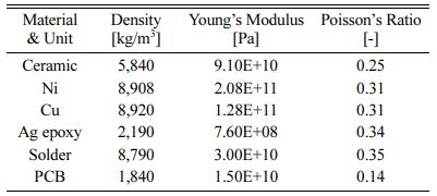
Board flex simulation was performed to determine the change in mechanical stress applied to the MLCC with Ag-epoxy electrode. The board flex simulation consisted of a structure in which the MLCC was mounted by soldering at the center of the PCB. The analysis was performed under the condition that a maximum bending displacement of 5 mm was maintained at the center for 5 s. The physical properties of the material used in the FEA simulation are shown in Table 1 [11-15]. The density, Young’s modulus, and Poisson’s ratio are required for stress analysis due to mechanical deformation.
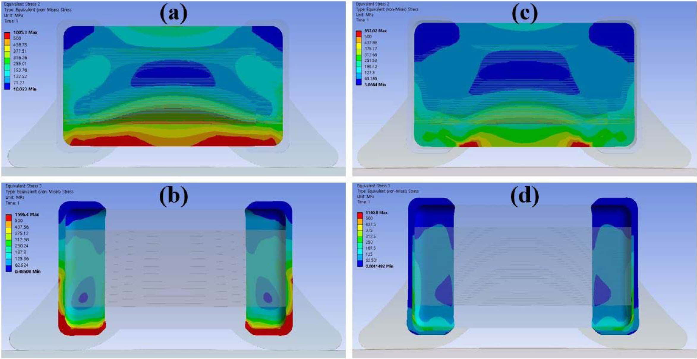
The result of the FEA simulation of standard and soft-termination types under 5-mm bending displacement conditions are shown in Fig. 1. As shown in Fig. 1(a) and (b), it can be observed that the maximum stress was applied in the contact area with external electrode at the bottom of the standard type MLCC. Conversely, in the soft-termination-type MLCC with Ag-epoxy electrode, the maximum stress point was the same. However, the magnitude and distribution of the applied stress were significantly reduced, as shown in Fig. 1(c) and (d).
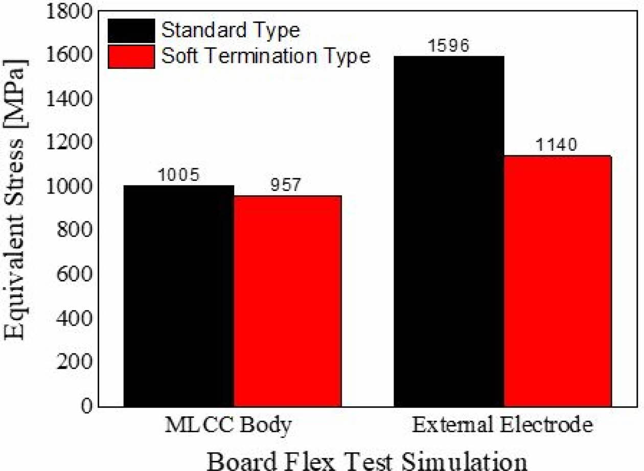
The equivalent stress values obtained using board flex simulation can be observed Fig. 2. The utilization of Ag-epoxy electrode decreased the stress generated in the MLCC body from 1005 MPa to 957 MPa. Addi- tionally, the stress induced in the external electrode deceased from 1596 MPa to 1140 MPa. Therefore, the stress reduction (of up to 28%) in the external electrode demonstrated the effectiveness of using Ag-epoxy electrode for mechanical stress relief.
Thermal Stress Simulation
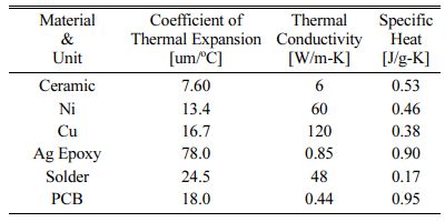
It is known that the thermal stress in MLCCs under rapid temperature change occurs due to the difference in the coefficient of thermal expansion (CTE) of the material [16]. The CTE mismatch of these components causes maximum stress in the contact region between the ceramic body and Cu external electrode of standard-type MLCC. In addition, thermal stress is maximized due to the high thermal conductivity of the Cu external electrode. Therefore, to alleviate these problems, Ag epoxy electrodes with a high CTE and low thermal conductivity are used to reduce thermal stress. Table 2 shows the properties of the materials used in the thermal shock simulation. The evaluation of stress caused due to thermal deformation requires information about CTE, thermal conductivity, and specific heat the materials [17-19].
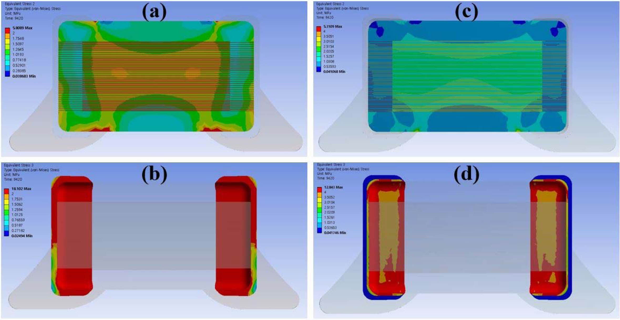
During the thermal shock simulation, three cycles of thermal analysis were performed while maintaining a low temperature (-55 oC) and a high temperature (+125 oC) for 30 min each for each cycle. Fig. 3(a) and (b) depict the FEM simulation results of standard type MLCC analysis, and the concentrated stress of the entire external electrode and the solder area due to the thermal shock environment can be observed. Fig. 3(c) and (d) depict that the concentrated stress in the Ag-epoxy area prevents the overall stress of the external electrode and it significantly alleviates the stress con- centrated in the solder contact area.
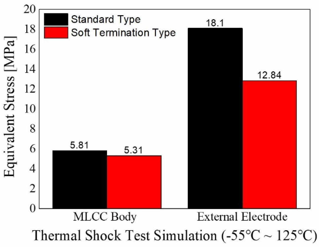
The stress generated in the thermal shock simulation can be observed in Fig. 4, and the result is similar to that of the board flex simulation in Fig. 2. Although the stress reduction in MLCC body due to the utilization of the Ag-epoxy electrode was insignificant (5.81 MPa to 5.31 MPa), the stress in the external electrode region was reduced by 29% (18.1 MPa to 12.84 MPa). Therefore, mechanical and thermal simulation demonstrated that Ag-epoxy electrode prevents the deformation due to mismatch of different properties of the materials.
|
Fig. 1 The result of FEM analysis as a function of under 5 mm bending displacement conditions (a) MLCC body area of standard type (b) External electrode area of standard type (c) MLCC body area of soft-termination type (d) External electrode area of soft-termination type. |
|
Fig. 2 The equivalent stress simulation result of board flex test under 5mm bending displacement conditions. |
|
Fig. 3 The result of FEM analysis as a function of thermal shock test (-55 oC ~ +125 oC) (a) MLCC body area of standard type (b) External electrode area of standard type (c) MLCC body area of soft-termination type (d) External electrode area of soft-termination type. |
|
Fig. 4 The equivalent stress simulation result as a function of thermal shock test (-55 oC ~ +125 oC). |
Board Flex Test
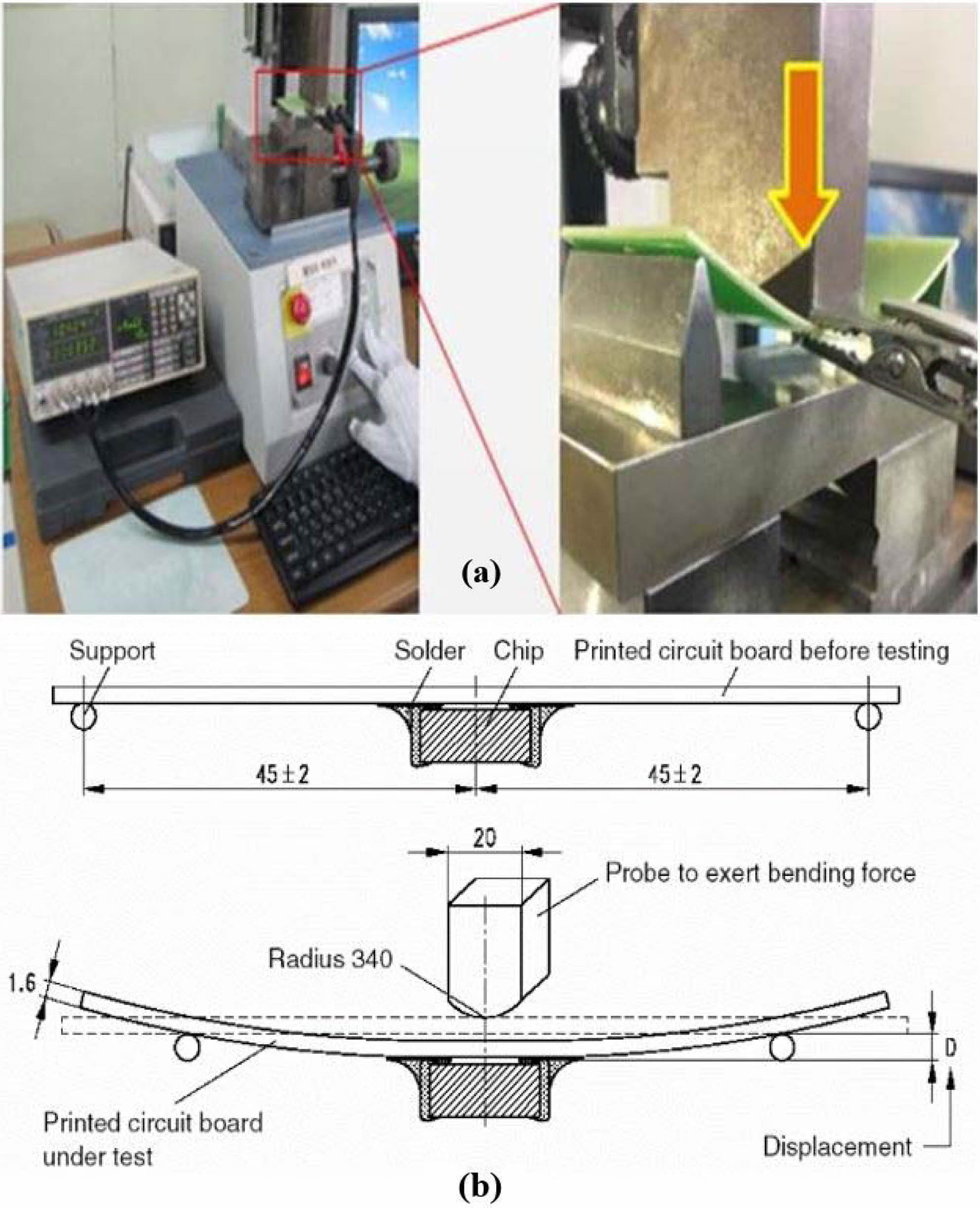
Fig. 5(a) represents a measuring equipment for board flex test, and it can be observed that the capacity is measured and recorded in real time while applying a force to the PCB board on which the MLCC was mounted. These tests involve subjecting a test board to a three-point bend test, similar to that of depicted in Fig. 5(b). The board flex test was evaluated based on the displacement of the post-test capacitance reduced by -12.5% of the initial capacitance ratio.
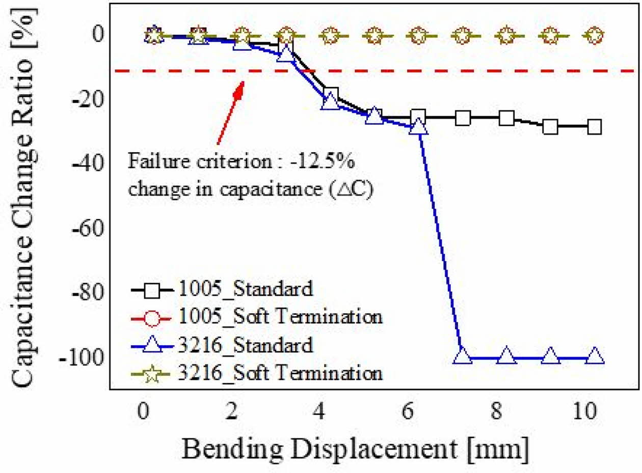
Fig. 6 depicts the board flex test results according to the MLCC chip size and external electrode. It can be observed from the board flex test results of standard and soft-termination types in Fig. 6 that the capacitance change ratio of soft-termination MLCC with Ag-epoxy electrode was approximately 0% up to 10-mm bending displacement. Conversely, the capacitance of the standard-type MLCC (1005 size) decreased from 4-mm bending displacement to below the -12.5% limit, and recorded approximately -35% until a 10-mm bending displacement. The standard-type MLCC with a 3216 size was similar to that of 1005 size up to 6-mm bending displacement. However, it exhibited a capacitance reduction rate of approximately -100% from 7-mm bending displacement. As a result of the board flex test, when Ag-epoxy was used, it was possible to verify the characteristics of the substrate bending resistance, and it can be observed that the possibility of bending cracking occurred when the MLCC size was increased.
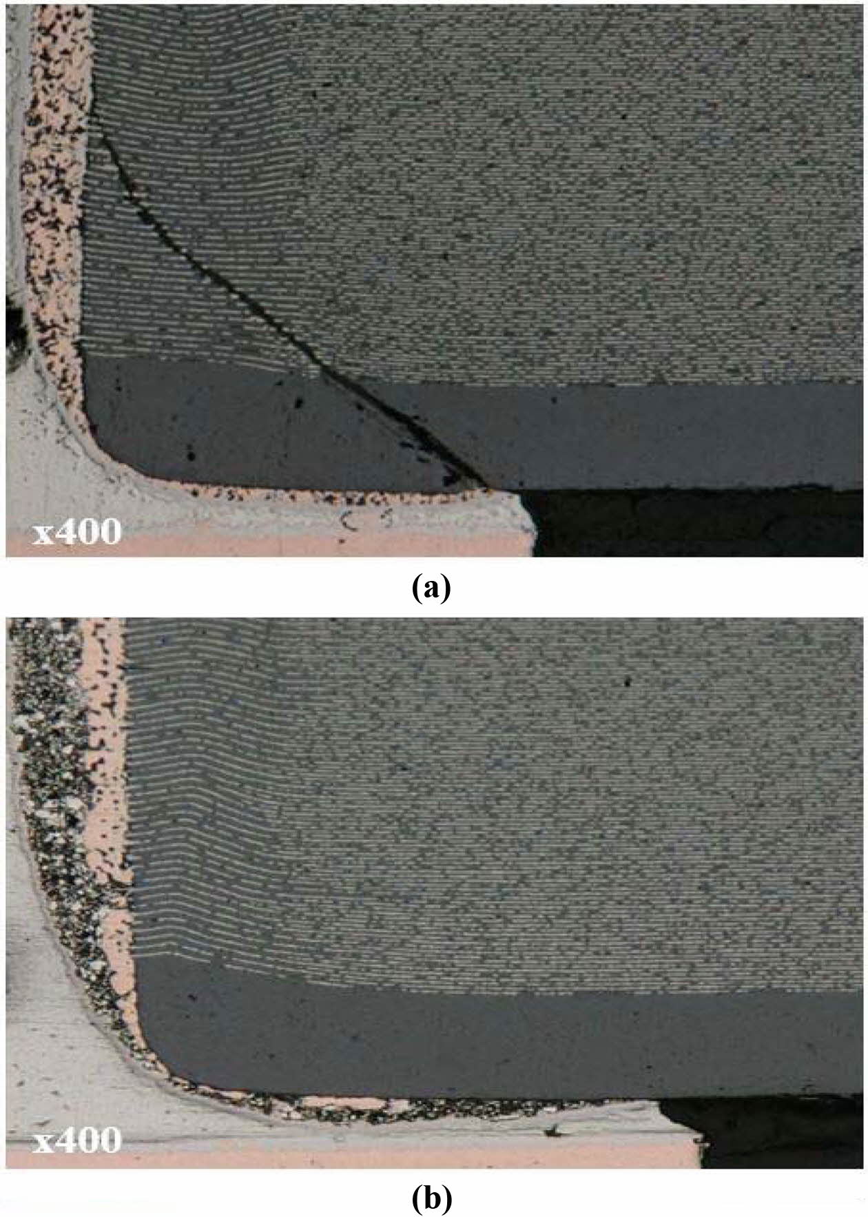
Fig. 7 shows the cross-sectional image after board flex test. The occurrence of cracks due to the bending force is shown in Fig. 7. In the standard-type MLCC, as shown in the FEA simulation analysis in Fig. 1, it can be observed that cracks were formed with the application of concentrated stress to the edge of the ceramic body and the Cu external electrode layer. In contrast, the soft-termination-type MLCC relieved stress in the Ag epoxy, which is a part of the external electrode layer, as shown in the FEA simulation crack in Fig. 1. Hence, cracks did not occur in the ceramic. As shown in Fig. 7(a), the morphology of the crack is similar to that of typical flexure fractures of MLCCs. The bending crack occurred at the contact part of the solder and the external electrode, and the bending crack penetrated the MLCC internal electrode at an angle 45 degrees and advanced to the external electrode region [20]. Conversely, in the case of soft-termination-type MLCC, the crack did not occur due to the utilization of Ag-epoxy electrode as shown in Fig. 7(b). Therefore, these results demonstrate that the mechanical properties of MLCC with Ag-epoxy electrode were significantly improved.
Thermal Shock Test
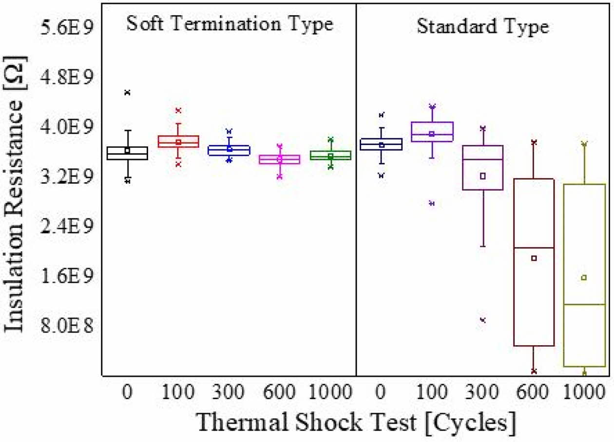
Fig. 8 depicts the results of insulation resistance according to the thermal shock test cycle. The thermal shock test was conducted for 1000 cycles, and it can be observed that the soft-termination type MLCC with Ag-epoxy exhibited thermal stability. Conversely, the standard-type MLCC exhibited a rapid decrease in insulation resistance after 300 cycles, and it was observed that the insulation resistance decreased to lower than 1.0E8 Ω at 1000 cycles. The cause of the decrease in insulation resistance was due to the effect of micro cracks due to abrupt temperature changes. As shown in the results of the simulation analysis according to the thermal shock in Fig. 3, it can be observed that the form of stress between the external electrode and the ceramic body interface of the standard-type MLCC and soft-termination MLCC is different. It can be observed that the stress between the external electrode and the ceramic body interface according to the thermal shock affects the stress distribution between the ceramic dielectric and the internal electrode. In particular, it can be observed that concentrated stress was generated in the internal electrode and ceramic dielectric part of the MLCC, and micro cracks were formed in the internal ceramic dielectric body and the insulation resistance decreased with an increase in the number of thermal shocks [21].
Temperature-Humidity-Bias (THB) Test
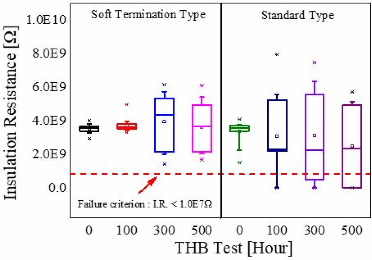
Fig. 9 depicts the results of insulation resistance according to the THB test. For the THB test, the standard-type and soft-termination-type MLCC samples were inserted into the THB test jig, and the rated voltage was applied at 85 oC/85% RH conditions for a duration of 500 h [22]. The two types of insulation resistance measured before the test were 3.5E9 Ω or greater. In the case of standard-type MLCC, the value of insulation resistance measured after 100 h exhibited a large standard deviation, and defective products falling below 1.0E7 Ω also occurred. In contrast to the standard-type MLCC, the insulation resistance of the soft-termination-type MLCC did not decrease to an insulation resistance of 1.0E7 Ω or lower even though the standard deviation of the insulation resistance measured after 300 h slightly increased.
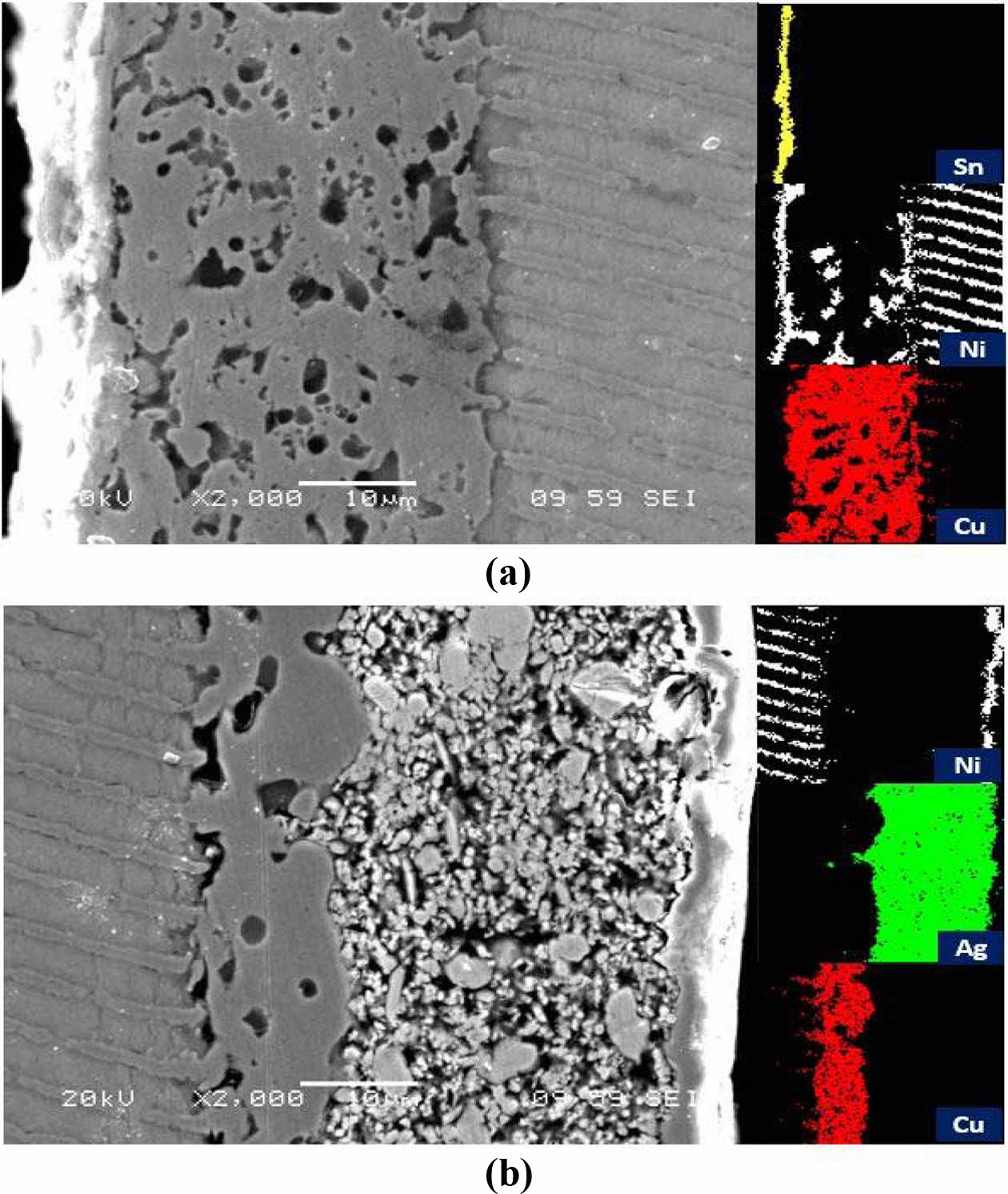
Fig. 10 shows scanning electron microscope (SEM) and energy-dispersive x-ray spectroscopy (EDS) images after conducting the THB test for 500 h. Fig. 10(a) depicts the results for the standard type MLCC, and it can be observed that the Ni plating filled the space between the Cu external electrodes. In addition, it was confirmed that the plating proceeded the Ni internal electrode region and were electrically connected to each other. It can be observed that during the Ni plating process, after the formation of the Cu external electrode, the Ni plating solution penetrated the empty spaces between the Cu external electrode and the Ni internal electrode area. Therefore, the penetration of the plating solution affected the MLCC reliability reduction [23, 24]. It can be observed in Fig. 10(b) that the high-density Ag-epoxy electrode prevented the Ni plating solution from penetrating inside, and it was considered that it had excellent moisture resistance properties during the THB test.
|
Fig. 5 The measuring equipment and industry standard (IEC-384-1) of the board flex test (a) Measuring equipment of the board flex test (b) Industry standard (IEC-384-1) of the board flex test. |
|
Fig. 6 The board flex test results according to the MLCC chip size and external electrode. |
|
Fig. 7 Cross-sectional image after board flex test (a) Standard type MLCC of 1005 size (b) Soft-termination type MLCC of 1005 size. |
|
Fig. 8 The results of insulation resistance as a function of thermal shock test cycle. |
|
Fig. 9 The results of insulation resistance as a function of temperature-humidity-bias test. |
|
Fig. 10 SEM and EDS results after 500hours of THB test (a) Standard type MLCC of 1005 size (b) Soft-termination type MLCC of 1005 size. |
In this study, reliability experiments and FEA simula- tions were performed on Ag-epoxy electrodes to improve the reliability of MLCC. First, mechanical and thermal simulations demonstrated that the stress applied to the MLCC was reduced by up to 29% due to the utilization of the Ag epoxy electrode. Second, the excellent bending resistance was confirmed using a board flex test through the utilization of an Ag epoxy electrode. In particular, through comparison of capacitance change rate, it was observed that the effect of the Ag epoxy electrode was prominent with an increase in the MLCC size. Third, a thermal shock test was conducted to investigate the effect of preventing solder deterioration of the Ag-epoxy electrode. Additionally, it was confirmed by the thermal shock test that the insulation resistance value of the standard type MLCC significantly decreased based on 300 cycles. However, the insulation resistance value of the soft-termination-type MLCC remained unchanged even after 1000 cycles. Finally, the excellent moisture resistance of the soft-termination-type MLCC were demonstrated during the THB test. Therefore, the advantages of using Ag-epoxy electrodes was demon- strated using FEA simulation and reliability evaluation. The synthesizing simulation and reliability test data demonstrated that the soft-termination-type MLCCs with high reliability characteristics are indispensable for existing applications and for applications in harsh environments such as automobiles and aerospace.
This work was supported by the National Research Foundation of Korea (NRF) grant funded by the Korean government (MSIT) (NRF-2021M1A3B2A01076907)
- 1. D.Y. Jeong, S.I. Lee, H.Y. Lee, M.K. Kim, and J.R. Yoon, Jpn. J. Appl. Phys. 52[10S] (2013) 10MB23.
-

- 2. J.H. Yoo, and S.J. Cho, Trans. Electr. Electron. Mater 20[1] (2019) 36-39.
-

- 3. V.O. Belko, O.A. Emelyanov, I.O. Ivanov, and A.P. Plotnikov, 2019 IEEE Conf. Electr. Electro. Eng. (EIConRus) (2019) 78-80.
-

- 4. J. Al Ahmar and S. Wiese, 16th Int. Therm. Mech. Multi-Phys. Simul. Exp. Microelectron. Microsyst, IEEE (2015) 1-5.
-

- 5. S. Majcherek, A. Aman, S. Hirsch, and B. Schmidt, Sens Actuators A. Phys. 233 (2015) 267-274.
-

- 6. M. Keimasi, M.H. Azarian, and M. Pecht, Microelectron Reliab. 47[12] (2007) 2215-2225.
-

- 7. J.R. Yoon, K.M. Lee, and S.W. Lee, Trans. Electri. Electro. Mat. 10[1] (2009) 5-8.
- 8. J.Y. Kim, S.H. Lee, J.R. Yoon, C.J. Van Tyne, K.Y. Ohk, and H.J. Lee, Test Eval. 44[4] (2016) 1593-1599.
-

- 9. M. Stewart, Proc. Symp. Passive. Compon, CARTS, Palm Springs, CA, USA., (2005) 21-24.
- 10. B. Sloka, D. Skamser, R. Phillips, A. Hill, M. Laps, R. Grace, J. Prymak, M. Randall, and A. Tajuddin, CARTS-CONFERENCE-. COMPONENTS TECHNOLOGY IN- STITUTE INC. 27 (2007) 125.
- 11. G.C. Scott, and G. Astfalk, IEEE Trans. Compon., Hybrids, Manuf. Technol. 13[4] (1990) 1135-1145.
-

- 12. C.H. Lee, and J.R. Yoon, J. Electl. Eng. Tec. (2021) 1-8.
- 13. T. Lu, X. He, Y. Zou, H. Wang, and B. Zhou, 18th Int. Conf. Electron. Packag. Technol. (2017) 1461-1465.
-

- 14. C.W. Huang, B.T. Chen, K.Y. Chen, C.H. Hsueh, W.C. Wei, and C.T. Lee, Int J Appl Ceram Technol. 12[2] (2015) 451-460.
-

- 15. K.Y. Chen, C.W. Huang, M. Wu, W.C.J. Wei, and C.H. Hsueh, J. Mater. Sci.: Materials in Electronics. 25[2] (2014) 627-634.
-

- 16. A. Teverovsky, IEEE Trans. Device Mater. Reliab. 12[2] (2012) 413-419.
-

- 17. S.P. Lee, J.H. Kim, D.J. Kim, and S.K. Ha, J. Compos. Mater. 47[13] (2013) 1593-1604.
-

- 18. M.S. Kang, Y.J. Jeon, D.S. Kim, and Y.E. Shin, Int J. Pre. Eng. Manuf. 17[4] (2016) 445-452.
-

- 19. W. Benhadjala, B. Levrier, I. Bord-Majek, L. Bechou, E. Suhir, and Y. Ousten, Int. [Conf.] Therm. Mech. Multi-Phys. Simul. Exp. Microelectron. Microsyst (EuroSimE), IEEE (2014) 1-6.
-

- 20. C. Andersson, O. Kristensen, E. Varescon, and F. Iannuzzo, 11th Int. Symp. Diagn. Electr. Mach. Power. Electron. Drives (SDEMPED), IEEE (2017) 608-614.
-

- 21. A. Teverovsky and J. Herzberger, CARTS Int. (2014) 15-29.
- 22. J. Gu, M.H. Azarian, and M.G. Pecht, Int. Con. Prognostics. Health. Manage (2008) 1-7.
-

- 23. W. Chen, L. Li, J. Qi, Y. Wang, and Z. Gui, J Am Ceram Soc. 81[10] (1998) 2751-2752.
-

- 24. D. Donahoe, C. Hillman, and M. Pecht, CARTS-CON- FERENCE-COMPONENTS TECHNOLOGY INSTITUTE INC (2003) 129-133.
 This Article
-
2022; 23(2): 181-187
Published on Apr 30, 2022
- 10.36410/jcpr.2022.23.2.181
- Received on Sep 16, 2021
- Revised on Nov 23, 2021
- Accepted on Nov 29, 2021
 Services
- Abstract
introduction
fea simulation
test and discussion
conclusions
- Acknowledgements
- References
- Full Text PDF
Shared
 Correspondence to
- Jung Rag Yoon
-
R&D Center, Samwha Capacitor, Yong-In, Korea
Tel : +82 31-330-5765 Fax: +82 31-332-7661 - E-mail: yoonjungrag@samwha.com


 Copyright 2019 International Orgranization for Ceramic Processing. All rights reserved.