- Edge shape effect on the glass strength
Byunghoon Kang, Cheolmin Park, Seungho Kim, Seongtaek Lee and Hoikwan Lee*
Display Research Center, Samsung Display Co., Ltd., Giheung-gu, Yongin-city, Gyeonggi-do, Korea
This article is an open access article distributed under the terms of the Creative Commons Attribution Non-Commercial License (http://creativecommons.org/licenses/by-nc/4.0) which permits unrestricted non-commercial use, distribution, and reproduction in any medium, provided the original work is properly cited.
In this study, the edge shape effect on the impact and bending strength of glass sheet was carefully investigated by using edge impact test (EIT) and 4-point bending (4PB) test. The Weibull data obtained from EIT showed that round shape was more resistance to impact test regardless of the tilted stage angle and the strength values were in the order of round shape, bevel shape, and cut shape. When it comes to the bending strength, it was insensitive to the edge shape unlike the impact strength. Fracture analysis proved that the origins were located around the grinned surface and the breakage behavior of round shape was different those of bevel and cut shape. The mirror strength was calculated by the means of measuring the mirror radius, and the relationship compared to the tensile stress was discussed in detail
Keywords: Edge shape, Impact strength, Bending strength, Glass processing, Fracture analysis
Glass materials are widely used for display technology. A manufactured large glass substrates were cut into a product size according to its usage. The mechanical strength of these glass products strongly depends on the finishing processes including cutting, grinding, conveying, and handling. That is the reason why the glass has a quite low strength than its theoretical strength [1].
In order to get close to theoretical strength of glass, the understanding, the influence of glass machining process, is necessary. Several research groups (V.I. Kondrashov et al. 2001; X. Li et al. 2020; M. Lindqvist & C. Louter 2014) reported the strength variation according to the glass finishing conditions. They emphasized that the optimized cutting condition and the removing edge flaw using the machining process were crucial [2-4]. B. Weller et al. reported that the bending strength of tempered glass decreased due to flaws resulting from regrinding process for excessive edge processing [5].
P.Y. Chen et al. and P. Bukieda et al. proved that the different edge shapes affected the impact strength as well as the bending strength. They studied how the impact strength was affected by the edge shape using a silicon wafer. Also they reported the difference in bending strength of glass according to the edge processing tool and shape [6, 7]. However the analysis of the impact strength and lifespan according to the impact angle, and the difference of bending strength and fracture behavior according to the edge shape were not clearly discussed well.
In this study, we analyzed the bending strength and impact strength according to the edge shape of the glass by measuring the 4-point bending (4PB) test and the edge impact test(EIT). The fracture analysis was conducted to understand how the fracture mechanisms were different according to the edge shape. The mirror strength was calculated and compared with the bending strength to verify the effect of edge shape on bending strength
The glass used in this study was a commercial alkaline-earth boro-alumino silicate glass (Lotus NXT, Corning, US) especially designed for high-performance display applications. The glass substrate was cut into a cell size, 150 mm x 74 mm x 0.5t and the edge was grinded with three different edge profiles shown in Fig. 1. The computerized numerical control (CNC) machine was used to make the edge shapes, and the tools, 400 mesh and 1000 mesh, were adopted for roughing and smoothing. After that, glass specimens were washed to remove glass particles. Generally chemical cleaning with HF is more favorable for removing the particles but it was not adapted because it affects glass strength by blunting the crack tips [8-12].
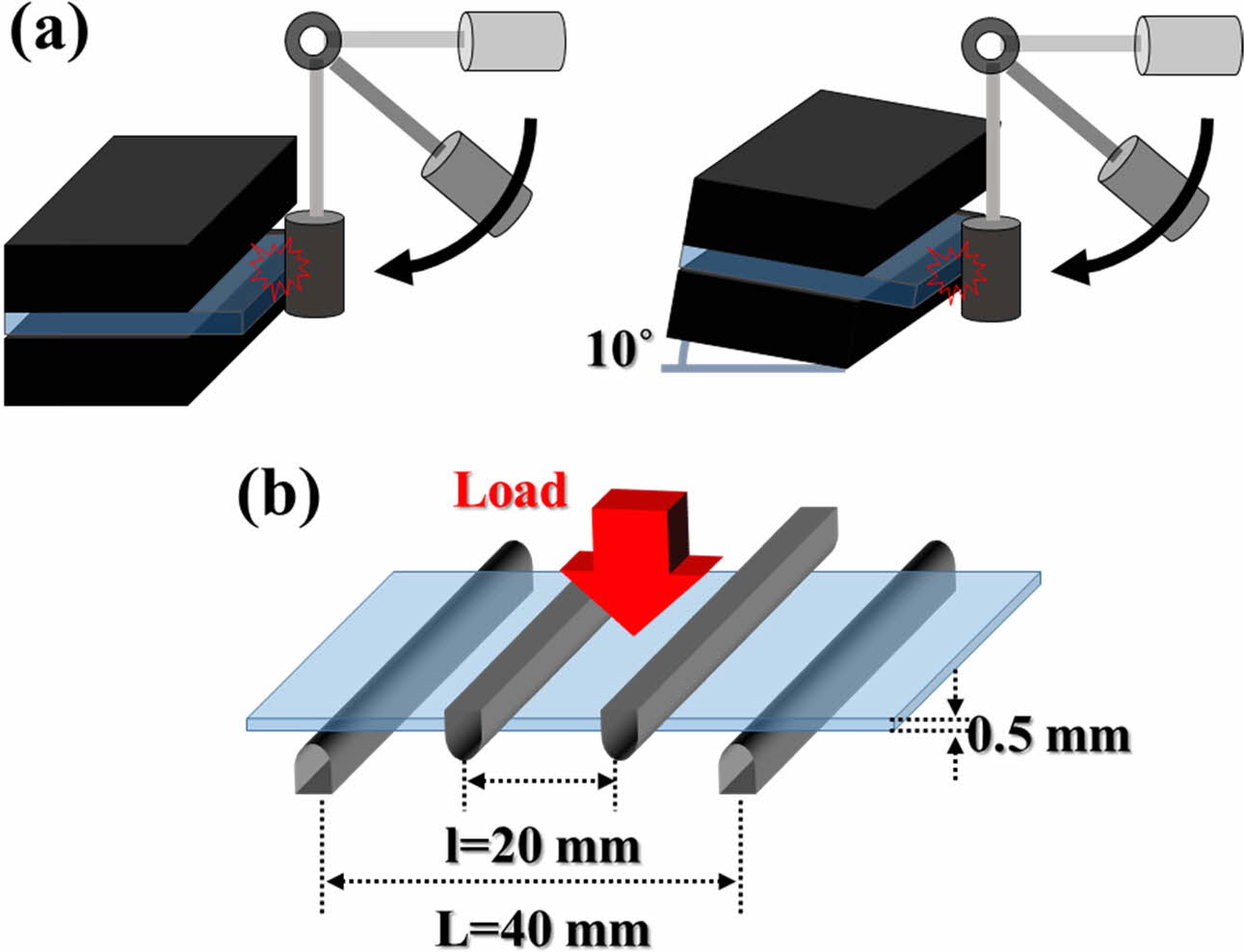
The edge shape and the fracture origins were con- firmed by using microscope (U-LH100-3, SEOUL ENGINEERING). The schematic diagram for the EIT was shown in Fig. 2(a) and the Auto EIT equipment (self-production, TESTONE) was available to control the stage tilting 0 ~ 10o. Universal Testing Machine (UTM, 5567-Q8495, INSTRON) was adopted for the 4PB test and the strength was calculated by using Eq. (1), where F represents the loading force, t is thickness and b means the width of specimen [13-15]. Here the loading rate was 10mm/min and the upper and lower span were 20mm and 40mm respectively.


|
Fig. 1 Microscope images of glass edge: (a) Round Shape (b) Bevel Shape (c) Cut Shape. |
|
Fig. 2 The Schematic Diagram of (a) EIT Test (b) 4PB Test. |
Edge Impact Strength
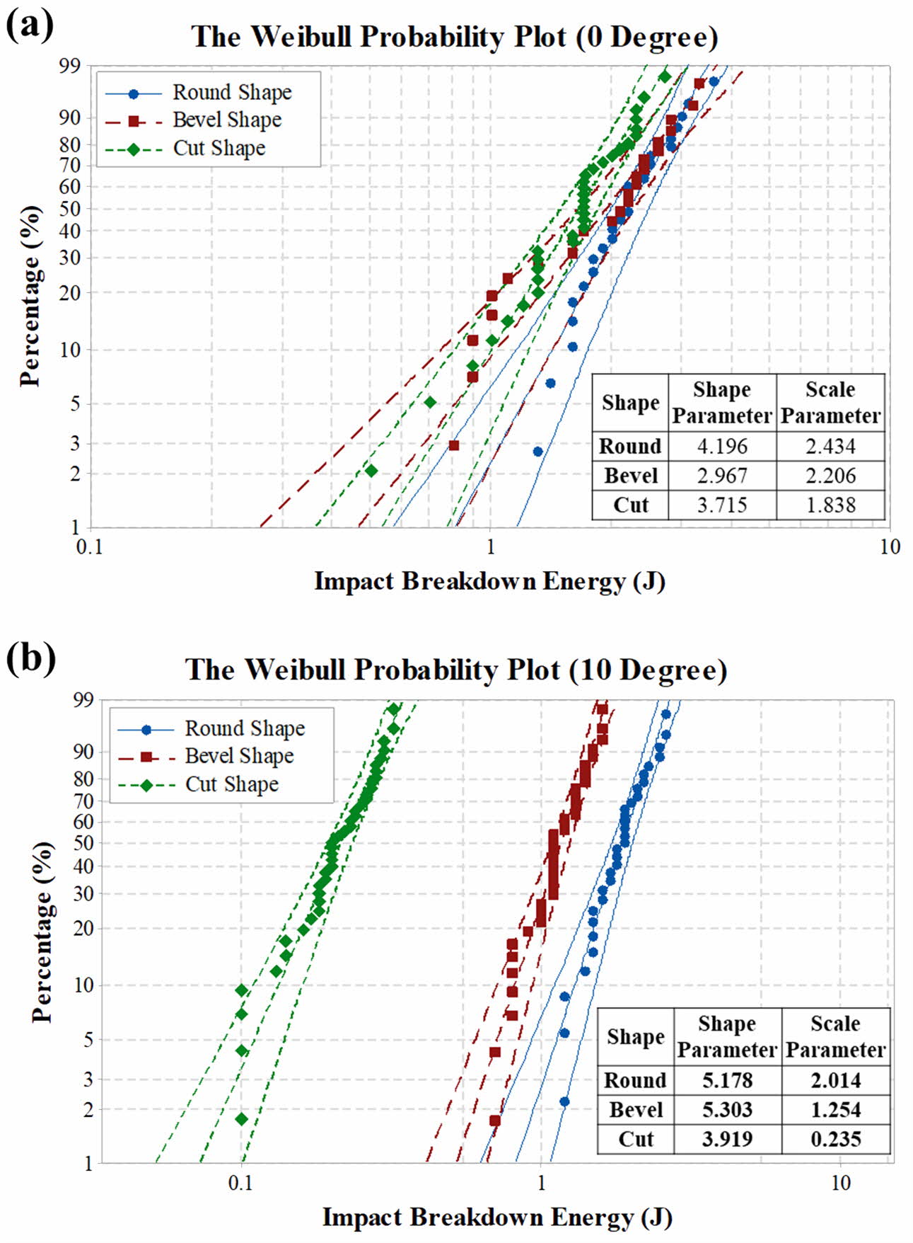
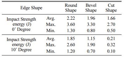
The results of edge impact strength as a function of tilting angle were summarized in Table 1. As seen in Table 1, the round shape showed more resistance to the impact energy compared to the others. The interesting point is that the edge shape effect was more and more critical when the impact angle increased from 0 to 10o degree, and the cut shape showed poor resistance to the impact.
Fig. 3 is showing the statistically organized Weibull plot. At zero degree, the difference of impact strength among round, bevel and cut shapes was relatively small as shown in Fig. 3(a). At 10 degrees however, the effect of edge shape on impact strength became clear as seen in Fig. 3(b). Round shape was keeping its impact strength regardless of the stage tilting but the impact strength of cut shape was remarkably dropped. It can be estimated that the round shape is the most advantageous for impact strength as well as the lifetime at impact.
Bending Strength
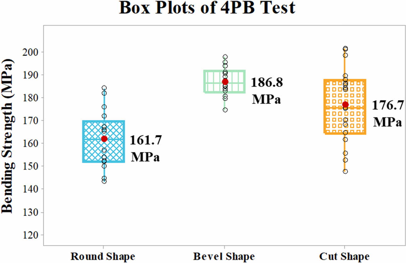
4PB test was generally carried out to measure the edge quality and the results were summarized in Fig. 4. As you can see in Fig. 4, the bending strengths were similar regardless of the edge shape and there was only 25 MPa difference among the three edge shapes. It is noticeable that the bending strength was insensitive to the edge shape unlike the impact strength. The bevel shape showed the smallest deviation of the interquartile range box among them. In other words, it can be said that the bevel shape is the most stable process in terms of bending strength.
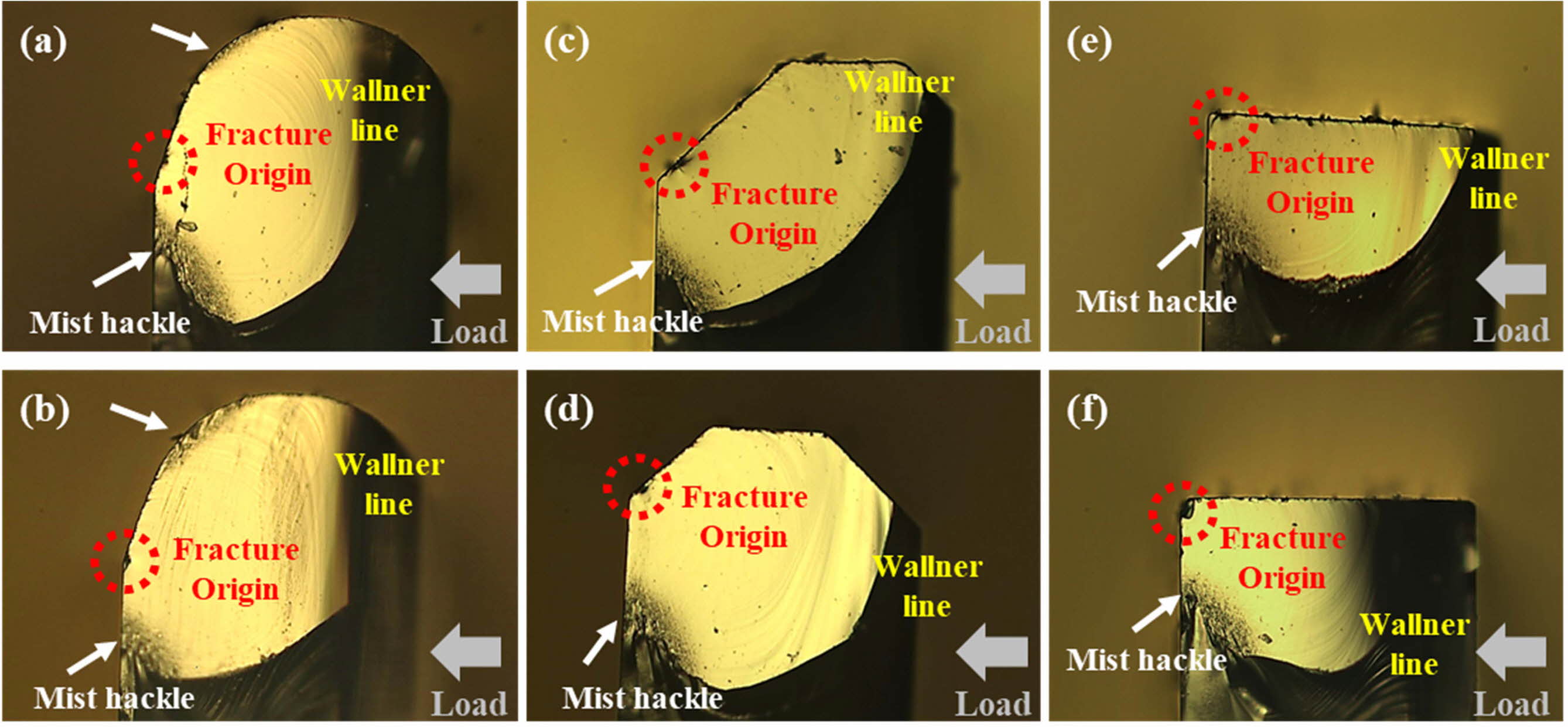
In order to find out the reason why the edge shapes in bending strength was insensitive, the fracture origin was analyzed by using optical microscope as shown in Fig. 5. Fracture images said that the fracture was caused by bending stress rather than uniform tension, and the fracture origins were located around the transition chamfer-plane. The interesting point is that the bevel and the cut shapes had corner breakage behavior. On the other hand, the round shape had a surface breakage behavior. When it is compared with the bending strength in Fig. 4, it is supposed to be said that the corner breakage behavior has relatively higher bending strength than the surface breakage behavior due to the machined surface area under the bending stress is small.
The edge shape effect on the bending strength was studied further by measuring the mirror strength. It is well-known that the mirror radius of the breakage origin can provide an estimate of tension stress level. In order to look into the correlation between the bending strength and the mirror strength, the mirror radius was measured using an optical microscope and calculated with Eq. (2) [16-21]

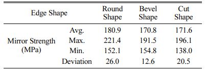
where σ is stress, R is the mirror radius which is the distance from the fracture origin to the mist hackle, and A is the mirror constant and just for calculation 65.3 MPa is used. The mirror radius was the distance from origin to mist in case the bevel and the cut shapes. In case of the round shape the length from mist to mist is divided by 2 and used as mirror radius “R”. The calculated bending strength is in Table 2.
Table 2 showed that the calculated bending strengths in each shape were similar, but there was a difference in standard deviation as same as experimental data in Fig. 4.
In this study, we discussed how the edge shape effects on edge impact strength as well as the bending strength of glass sheet. EIT results showed the round shape was resistance to impact test regardless of the tilted stage angle and the impact strength was decreased slightly from 2.2 J to 1.85 J with increasing the tilting angle. However, the impact strength of the bevel and cut shape was decreased sharply with increasing the tilting angle as shown in Table 1. When it comes to the bending strength, on the other hand, we found that the bending strength was insensitive to the edge shapes unlike the impact strength and there was only 25 MPa difference among the three edge shapes as seen in Fig. 4.
Fracture analysis to understand the broken mechanism indicated that the fracture was caused by bending stress and the origins were located around the transition chamfer-plane. Also we found out that the bevel and the cut shapes had corner breakage behavior and the round shape had a surface breakage behavior as shown in Fig. 5. The edge shape effect on the bending strength was studied further by calculating the mirror strength, and the results proved again that the mirror strengths in each shape were similar as same as experimental data in Fig. 4.
|
Fig. 3 Weibull plots for data sets of EIT: (a) Tilted 0 Degree (b) Tilted 10 Degree. |
|
Fig. 4 Box plots of 4PB Test. |
|
Fig. 5 Microscope Images of Fracture Origin: (a, b) Round Shape, (c, d) Bevel Shape, (e, f) Cut Shape. |
The impact and bending strength according to the edge shapes were compared. EIT results showed the round shape was resistance to impact test regardless of the tilted stage angle, by contrast the impact strength of the bevel and cut shape was decreased sharply with increasing the tilting angle. However, the bending strength was insensitive to the edge shapes unlike the impact strength and the mirror strengths in each shape were similar as same as experimental data. Fracture analysis to understand the broken mechanism indicated that the origins were located around the transition chamfer-plane, and the bevel and cut shapes had a corner breakage behavior, comparing that the round shape had a surface breakage behavior.
- 1. R. Lehman, in “The Mechanical Properties of Glass” (Rutgers University, 1998) p. 1-15.
- 2. V.I. Kondrashov1, L.A. Shitova1, V.A. Litvinov1 and V.V. Surkov, Glass Ceram. 58[9-10] (2001) 303-305.
-

- 3. X. Li, L. Jiang, M. Wang, J. Liu1, J. Li1 and Y. Yan, in E3S Web of Conf., December 2020 (ACIC 2020) 213[03011] p1-4.
-

- 4. M. Lindqvist and C. Louter, Eng. Fract. Mech. 127 (2014) 56-70.
-

- 5. B. Weller, K. Lohr and M. Engelmann, Challenging Glass 5 5 (2016) 219-232.
- 6. P.Y. Chen, M.H. Tsai, W.K. Yeh, M. H. Jing and Y. Chang, Microelectron. Eng. 87 (2010) 2065-2070.
-

- 7. P. Bukieda, K. Lohr, J. Meiberg and B. Weller, Glass Struct. Eng. 5 (2020) 411-428.
-

- 8. G. Spierings, J. Mater. Sci., 28 (1993) 6261-6273.
-

- 9. T. Suratwala, W. Steele, L. Wong, M.D. Feit, P.E. miller, R. Dylla-Spears, N. Shen, and R. Desjardin, J. Am. Ceram. Soc. 98[8] (2015) 2395-2402.
-

- 10. L.M. Cook, J. Non-Cryst. Solids 120[1-3] (1990) 152-171.
-

- 11. T.P. Dabbs and B.R. Lawn, J. Am. Ceram. Soc. 65[3] (1982) C37-C38.
-

- 12. H.K. Lee, B.B. Kim, Y.R Kim, M.K. Kim, S.H. Kim, and S.T. Lee, J. Ceram. Process. Res. 21[5] (2020) 547-551.
-

- 13. M. Zaccaria and M. Overend, in Engineered Transparency in International Conference at Glasstec, Düsseldorf, October 2012 (2012) p.1-9.
- 14. T.C. Tseng, H.Y. Hou, S.S. Hsu, B. Wang, L.W. Shih, J.J. Lih and C.Y. Chuang, SID DIGEST (2013) 44[1] 1144-1147.
-

- 15. M.H. Lin, W.W. Pan, P.J. Cheng and K.F. Huang, SID DIGEST (2014) 45[1] 697-700.
-

- 16. S. Kim and S. Choi, J. Inf. Disp. 18[1] (2017) 19-24.
- 17. S. Agnetti, Frattura ed Integrità Strutturale 26 (2013) 31-40.
-

- 18. T. Ono and R.A. Allaire, in “Fracture Analysis, a Basic Tool to Solve Breakage Issues, Technical Information Paper 201” (Taiwan FPD Expo, 2000) p.1-9.
- 19. G.D. Quinn, Fractogr. Glasses Ceram. V: Ceram. Trans. 199 (2007) 163-187.
- 20. J.J. Mecholsky, R.W. Rice and S.W. Freiman, J. Amer. Ceram. Soc. 57[10] (1974) 440-443.
-

- 21. M. Lindqvist and J.P. Lebet, Eng. Fract. Mech. 119 (2014) 43-52.
-

- 22. H.K. Lee, J.W. Park, C.M Park, J.H. Yeum and S.H. Kim, J. Ceram. Process. Res. 15[6] (2014) 411-417.
 This Article
-
2022; 23(2): 145-148
Published on Apr 30, 2022
- 10.36410/jcpr.2022.23.2.145
- Received on May 21, 2021
- Revised on Oct 25, 2021
- Accepted on Oct 30, 2021
 Services
Shared
 Correspondence to
- Hoikwan Lee
-
Display Research Center, Samsung Display Co., Ltd., Giheung-gu, Yongin-city, Gyeonggi-do, Korea
Tel : +82-31- 5181-6566 Fax: +82-31-8000-6822 - E-mail: hoikwan.lee@samsung.com


 Copyright 2019 International Orgranization for Ceramic Processing. All rights reserved.