


- Effect of K2CO3 additive on crystallinity and piezoelectric properties of KNNS-BZ-BKH ceramics
Lihaowen Zenga, Rabie Beniouba and Kenji Itakab,*
aGraduate School of Science and Technology, Hirosaki University, 1 Bunkyo-cho, Hirosaki, Aomori, 036-8560, Japan
bInstitute of Regional Innovation, Hirosaki University, 2-1-3, Matsubara, Aomori, 030-0813, JapanThis article is an open access article distributed under the terms of the Creative Commons Attribution Non-Commercial License (http://creativecommons.org/licenses/by-nc/4.0) which permits unrestricted non-commercial use, distribution, and reproduction in any medium, provided the original work is properly cited.
In this study, the piezoelectric ceramics, (0.955) K0.48Na0.52Nb0.9Sb0.1O3-(0.025) BaZrO3-(0.02) Bi0.5K0.5HfO3 (KNNS-BZ-BKH) with m mol% K2CO3 additives in the range of m = 0.0 to 3.96 have been successfully fabricated using the solid-state reaction method. The effect of K2CO3 on the sintering behavior, structure, microstructure, and electrical properties of KNNS-BZ-BKH ceramics was investigated. The experimental results showed that the addition of K2CO3 improved the sintering process of KNNS-BZ-BKH, which exhibited a well-sintered ceramic with a dense and pure perovskite structure stoichiometrically. At an optimal sintering temperature of 1210 oC and K2CO3 content of 2.64 mol%, enhanced physical properties of the ceramics such as density 4.0 g cm-3 and piezoelectric constant d33 = 75 pC/N were obtained through enhancement of KNNS-BZ-BKH microstructures with the best results exhibiting a pure perovskite phase with no secondary phases due to crystallinity improvement
Keywords: KNN-based, Ceramics, Crystallinity, Piezoelectric, Lead-free
Piezoelectric materials are enablers of conversion between mechanical and electrical energy in both direc- tions through transducer elements from ignitors, actuators, and sound generators to filters and sensors [1-4]. Lead-based ceramics such as Pb(Zr,Ti)O3 (PZT) dominated the piezoelectric materials market for electronics and energy industry applications in the last century because of their excellent properties and flexibility in terms of compositional modification [5-9]. However, due to their harmful nature, the appearance of new regulations, and the expansion of Restriction of Hazardous Substances of the European Union (RoHS), the development of lead-free materials with the same level attracted much attention [10-14]. Alkali niobate system (K, Na) NbO3 abbreviated (KNN-based) materials have been considered one of the most promising candidates to replace lead-based piezoelectric materials, among the other alternative replacements due to their excellent piezoelectric constant (d33), high Curie temperature, and their good compre- hensive performance [15-19]. Saito et al. reported an impressive d33 of over 400 pC/N for Sb-introduced KNN grown by reactive-template grain growth [20]. Further- more, the KNN-based ceramics piezoelectric response highly depends on temperature due to their polymorphic phase boundaries (PPB) instead of morphotropic phase boundaries (MPB) characterizing PZT-based materials [21-27]. In order to overcome this problem, the addition of various materials improved temperature stability by shifting the corresponding TO-T (orthorhombic-tetragonal) below room temperature [28-29]. The effect of various additives on the phase transition temperatures and elec- trical properties in the series of KNN-based ceramics were investigated [30], such as Bi0.5A0.5ZrO3 (A = K, Na, Ag) [31], (Li, K,Na)(Nb,Sb)O3-(Bi,Na,Sr)ZrO3 with dopants CuO, B2O3, ZnO [32], (K, Na)(Nb,Cu)O3-SrZrO3 [33], and (Na, Bi)TiO3-(Ba, Ca)(Ti, Zr)O3-(K, Na)NbO3 [34]. Xu et al. reported a giant d33 of ~570pC/N using Sb5+, BaZrO3, and Bi0.5K0.5HfO3 (KNNS-BZ-BKH) as additives to shift their TR-O (rhombohedral-orthorhombic) as well as TO-T to or near room temper- ature fabricated by the conventional solid-state method [35].
Moreover, the conventional solid-state sintering pro- cess results illustrated difficulties of the process for KNN-based dense ceramics [36]. Various research works on substitute methods that enhance the density of the fabricated KNN ceramics have been conducted, such as plasma [37], hot temperature processing [38], and recently two-step sintering method, which is showing high efficiency for the enhanced piezoelectric properties on the KNN-based ceramics [39]. However, due to the lack of a clear understanding of the relationship between the sintering temperature and the crystallinity of KNN-based ceramics and their impact on the piezoelectric constant (d33) at room temperature, it is mandatory and inevitable to elucidate the different aspects of the modified sintering process effect on both KNN-based microstructures and piezoelectric properties.
In this work, we investigated the effect of sintering temperature and K2CO3 as additives on the crystallinity and piezoelectric properties of 0.955K0.48Na0.52Nb0.9Sb0.1O3-0.025BaZrO3-0.02Bi0.5K0.5HfO3 (abbreviated as KNNS-BZ-BKH) ceramics. The crystallinity dependency on the sintering temperature and the K+ additive content, in addition to the resultant piezoelectric properties of KNNS-BZ-BKH sintered at 850 oC and 1210 oC, are discussed in terms of microstructures and formation defects.
The KNNS-BZ-BKH + m K2CO3 piezoelectric ceramics, where m = 0.0, 0.66, 1.32, 1.98, 2.64, 3.30 and 3.96 mol%, that is, approximately m = 0, 0.5, 1, 1.5, 2, 2.5 and 3 wt%, were synthesized by a conventional solid-state reaction method. In order to prepare the KNNS-BZ-BKH piezoelectric materials, 99.9% raw reagent-grade of Bi0.5K0.5HfO3, BaZrO3, K0.48Na0.52Nb0.9Sb0.1O3, and K2CO3 were used as starting materials. Firstly, the materials were weighed, mixed according to their stoi- chiometric composition, and milled with the appropriate volume of ethanol in a planetary micro ball mill (Pul- verisette) for 24 h with Agate balls. After dry up the ethanol, the powders were calcined at 850 oC, 1100 oC, and 1210 oC for 6 h to compare the effect of calcination temperature on the crystallinity of KNNS-BZ-BKH shown in Fig. 1(a). Then the calcined powders with 850 oC were processes by polyvinyl alcohol (PVA) into compacted disks with diameters of 10 mm and thickness of 1~2 mm. After the PVA was burned off, the pellets were sintered at 1090~1210 oC for 6 h. Silver electrodes on both sides of the sintered pellets were made with silver paint (DuPont, #4922) and polarized under a direct current electric field of 13~18 kV/cm in a silicone oil bath at 50-100 oC for 10-120 min as shown in Fig. 1(b).
The structural properties of the calcined powder with various temperatures and with different K additives were characterized using x-ray diffraction (XRD) with a Cu-Kα (λ= 0.15405 nm) radiation source in the angular range of 20o ≤ 2θ ≤ 90o and at a scan rate of 10 o/min was employed by an x-ray diffractometer (Smartlab, Rigaku Corporation). Full Width at Half Maximum (FWHM) was determined by Voigt function fitting. A scanning electron microscope (SEM, Hitachi SU8010) equipped with an energy dispersive spectro- meter (EDS, HORIBA Scienti-fic) analyzer was used for microstructure and composition analysis. The oxygen component was excluded in the estimation to remove the effect on the other elements due to the significant error of EDS peaks on the light element. The piezoelectric properties were measured using Piezoelectric Constant (d33) Calibrator (YE2730A, SINOCERA PIEZOTRONICS INC.).

|
Fig. 1 Flow chart of the fabrication process for (a) powder samples and (b) pellet samples. |
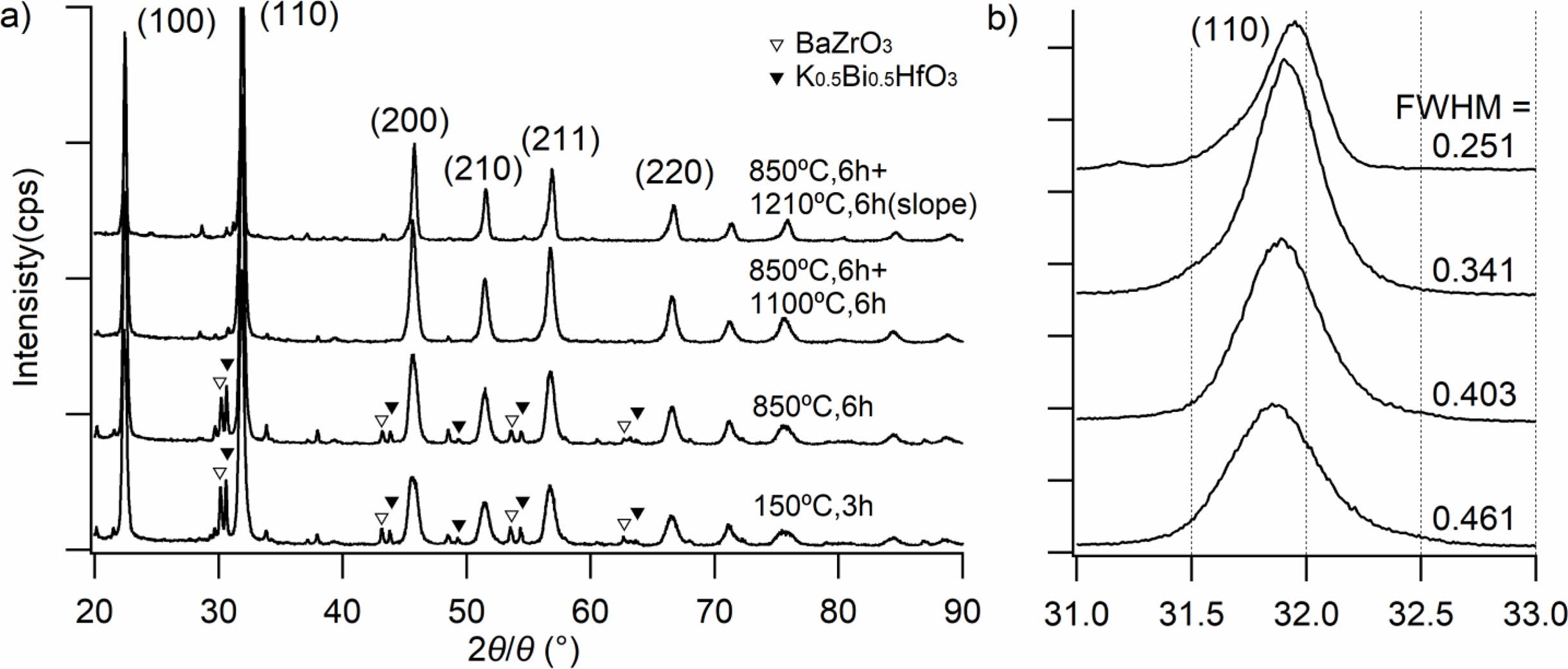
Fig. 2(a) shows the powder XRD patterns of the KNNS-BZ-BKH powder prepared without K2CO3 additive (i.e., m = 0) measured after the following heat treatments: (T1) just after heat treatment at 150 oC for 3 h for ethanol removal, (T2) firstly, calcination at 850 oC for 6 h, (T3) two-step calcination of firstly at 850 oC for 6 h, and secondly at 1100 oC for 6 h, and (T4) two-step calcination of firstly with 850 oC for 6 h and secondly temperature profile with gradually change from 1210 oC to 1090 oC for 6 h. A perovskite structure without a secondary phase was observed for calcined heating patterns of (T3) and (T4). The unreacted raw material peaks as secondary phases in the case of (T1) and (T2) were observed at 2θ = 22o (corresponding to KNNS), at 2θ = 30o, 43o, and 54o (BaZrO3), at 2θ = 47o and 64o (Bi0.5K0.5HfO3). Fig. 2(b) shows the enlarged peaks of (110) in the 2θ range of 31o to 33o. Broad (110) peaks in only the cases of (T1) and (T2) were observed (FWHM of (T1) = 0.461o, FWHM of (T2) = 0.403o), while sharp (110) peaks in the case of (T3) and (T4) were observed (FWHM of (T3) = 0.341o, FWHM of (T4) = 0.251o). The (110) peaks moved towards higher angles due to the formation of the KNNS-BZ-BKH perovskite structure. In additional experiments, we found that the secondary heating at a fixed temper- ature of 1210 oC causes the decomposition of the samples. So, we could conclude that the calcination process with (T4) temperature profile was optimal in the viewpoint of the crystallinity and endorsed the formation of perovskite structure based on the XRD results obtained for KNNS-BZ-BKH powder calcination.
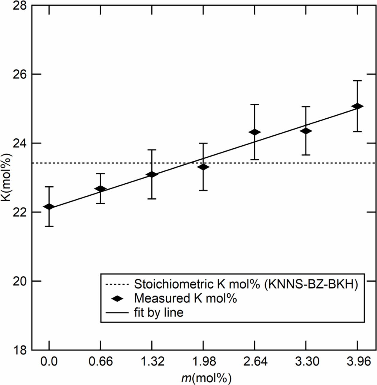
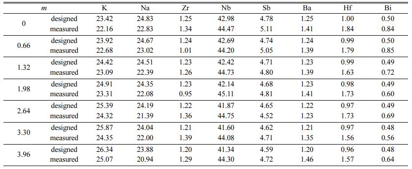
Fast forward, we focused on the study of the effect of adding various molar ratios of K2CO3. Fig. 3 shows estimated potassium mol% (except oxygen) by SEM/EDS as a function of additive K2CO3 (m mol%). The estimated potassium increased linearly in the range of 22 to 25 mol% with varying m. This result shows the stoichiometric component for K around 1.98 mol% as optimal. Table 1 shows the molar ratios of Na, Zr, Nb, Ba, Hf, and Bi (mol%) estimated by EDS analysis and calculated by starting compositions as a function of K2CO3 additives (m mol%). In the case of m = 0, the molar ratio of each element is approximately consistent in the estimation and the calculation. However, the molar ratio of K is relatively lower as compared with other elements. Therefore, the K2CO3 additive is effective in compensating for the lack of potassium. All elements except K were approximately independent of the K2CO3 additives.
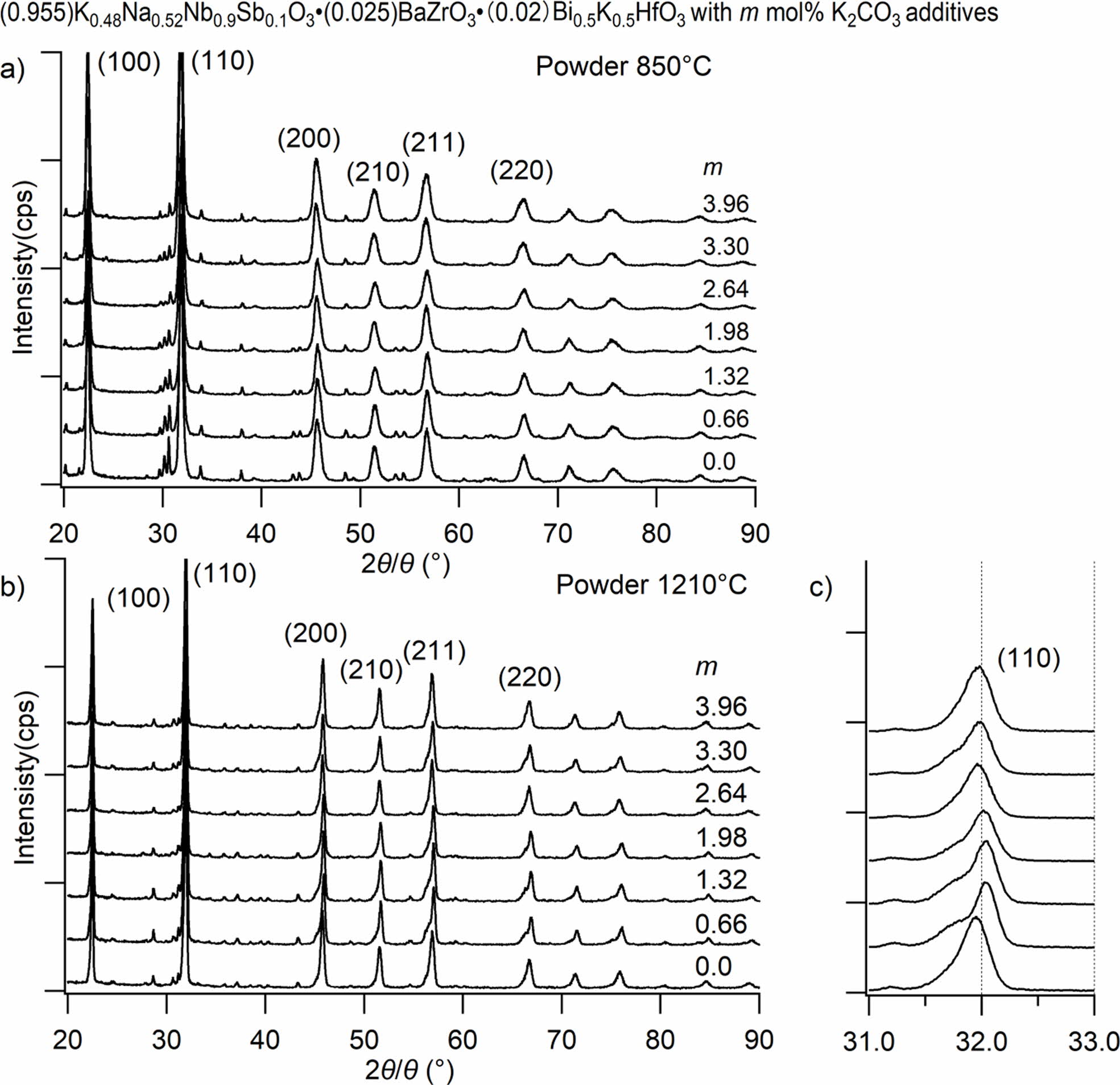
Fig. 4 shows XRD diffractions patterns corresponding to KNNS-BZ-BKH ceramics powder doped with different K2CO3 amounts (0 to 3.96 mol%) and calcined with (T2) temperature profile (850 oC) in Fig. 4(a) and (T4) temperature profile (1210 oC) in Fig. 4(b). The presence of a predominant phase related to KNNS with a main orthorhombic perovskite structure has been detected. Small peaks associated with the presence of a secondary phase can be assigned to partially unreacted powder mixture or impurities when calcined under (T2) condition and decreasing with an increase in K2CO3 additives (m mol%). In the case of the calcination under (T4) con- dition, Fig. 4(b) shows a significant decrease in impurity phases even at m = 0. In contrast, a more decrease in impurity phases is shown with an increase in m led to further suppression of secondary phases. The precise evaluation of the K2CO3 m mol% additive effect on the crystallinity of KNNS-BZ-BKH ceramics, Fig. 4(c) shows an XRD diffraction peak corresponding to (110) at 2θ = 31.8o for KNNS-BZ-BKH powder calcined with (T4) condition. The location of (110) peak increased from m = 0 to 1.98~2.64 mol%, which corresponds to the stoichiometry of K mol% value as shown in Fig. 3. While, the increase in the additive m over 2.64 mol% led the location of (110) peak to decrease slightly towards lower angles due to excess of K2CO3 additives, as shown in Fig. 3.
These results showed that K2CO3 m mol% additive has an optimal range of 1.98~2.64 mol% in which KNNS-BZ-BKH crystallinity is enhanced via impurity phases removal or entirely reaction of mixture led to the appearance of perovskite structure without secondary phases induced by unreacted raw materials due to highly volatile K element during sintering process with (T4) condition. The diffraction peaks shift toward a higher angle with increasing K2CO3 addition since it is expected that K+ (0.164 nm) could substitute for Bi3+ (0.14 nm) and Na+ (0.139 nm). Only an orthorhombic phase with a perovskite structure was observed. It indicates that the addition of small amounts of K2CO3 (0~3 wt%) did not give rise to an apparent change in the crystal structure.
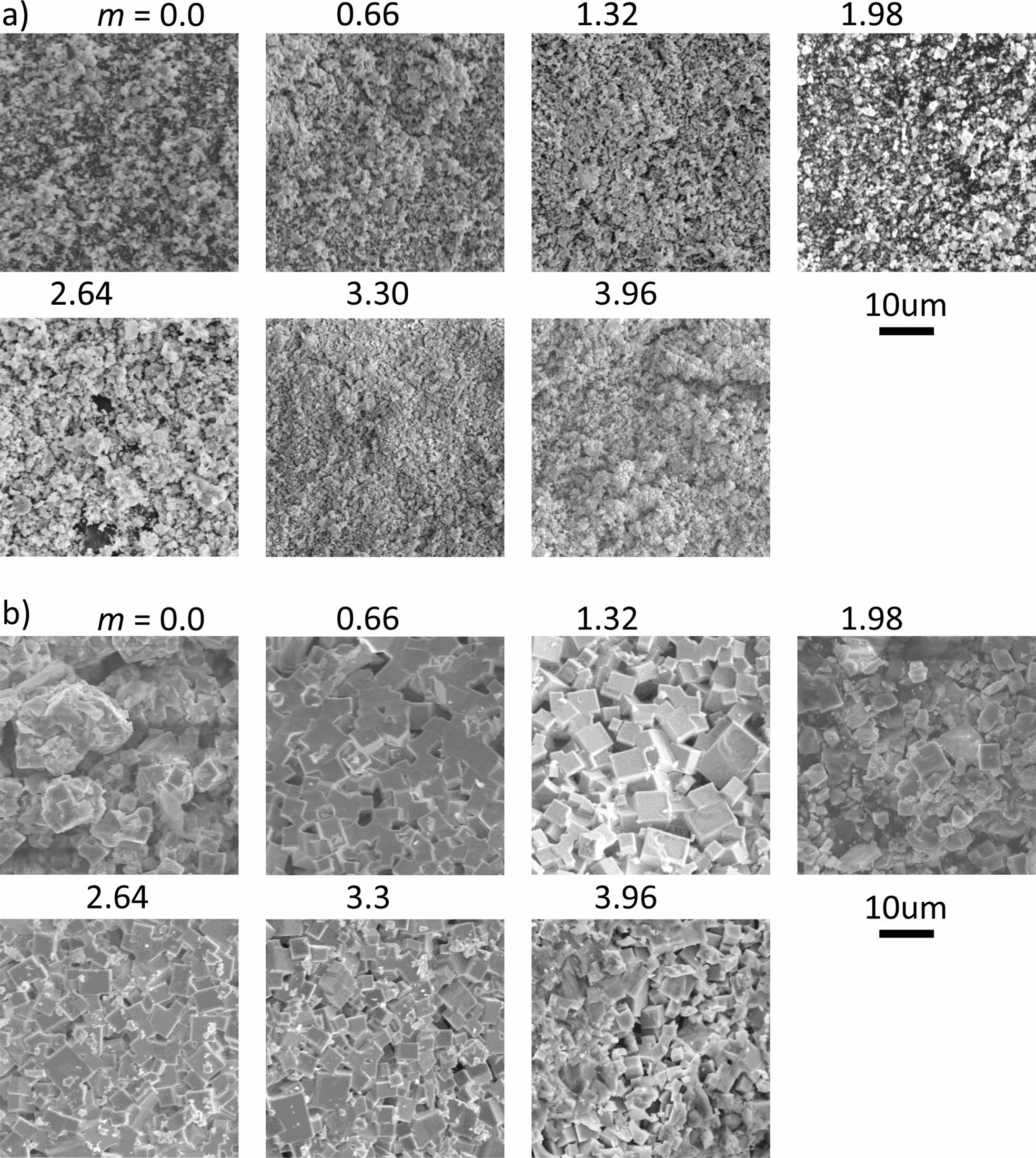
Fig. 5 shows the SEM images of the KNNS-BZ-BKH with 0~3.96 mol% K2CO3 additives, ceramics sintered with (T2) temperature profile (850 oC) in Fig. 5(a) and (T4) temperature profile (1210 oC) in Fig. 5(b). The pure KNNS-BZ-BKH ceramic powder sintered with (T2) temperature profile exhibited a small grain size (200-300 nm), and no noticeable change in the morphology of the specimen occurred even with various amounts of K2CO3 additive. On the other hand, in the case of the (T4) temperature profile, the facets based on the crystal structure were observed. The micro- structure in which abnormal grains larger than 700 nm and average grains of 300 to 700 nm coexisted was observed with dense microstructure due to overall grain growth. The most apparent facets were observed at m = 1.32, but the gaps between the grains were rather large. It seems that additives with m = 1.98 to 3.3 show denser morphology, with facets being nucleated. This change in the grain gap may be correlated with the change in the (110) peak shown in Fig. 4(c).
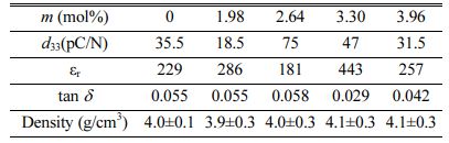
Table 2 shows the specimens' bulk density and piezoelectric properties sintered with (T4) temperature profile (1210 oC). We faced difficulty forming the pellet and polarization due to the following reasons in our current process: (1) the pellet in the alumina crucible melted and stuck to the alumina crucible. (2) the pellet was broken into pieces during the polishing process due to the fragile and sparse pellets. (3) the pellet could not be polarized enough due to the leak current between the electrodes. Due to these difficulties of the palletization and polarization process, the m = 0.66 mol% and 1.32 mol% samples could not be made into well-polarized pellets. Here, we investigated only the successfully made pellet according to the amount of K2CO3 additive (m = 0, 1.98, 2.64, 3.3, and 3.96 mol%).
The measured density of KNNS-BZ-BKH ceramics as a function of K2CO3 addition slightly increases with increasing K2CO3 additives. The piezoelectric charge coefficient (d33) of pure KNNS-BZ-BKH ceramic without additive was 35.5 pC/N while adding K2CO3 m = 1.98 mol% led to a decrease of d33 value to almost half 18.5 pC/N despite exhibiting a better crystallinity in Fig. 4. Nevertheless, d33 increased with additive m = 2.64 mol% to 75 pC/N, consistent with the XRD diffraction patterns for powder in Fig. 4(c) and SEM images exhibiting higher grain growth in Fig. 5(b). The d33 values of the ceramics with additive over m = 2.64 mol% exhibited a sharp decrease due to excess of K2CO3 additive leading to poor crystallinity and smaller grains. The sample size of the crystal and the gaps between the grains observed in SEM images of Fig 5(b) seem to influence the piezoelectric properties strongly. All the pellets showed almost the same density, and the dielectric constant and dielectric loss did not change significantly except for m = 3.3 mol% pellets. The pellet of m = 3.3 mol% may have an unknown problem in our pelletizing process.
|
Fig. 2 XRD patterns of powder under different heating patterns (m = 0): (a) the XRD pattern between 20⁰ and 90⁰; (b) the XRD pattern between 31⁰ and 33⁰. |
|
Fig. 3 The molar ratio (mol%) of potassium K with additive m. |
|
Fig. 4 XRD patterns of powder with different m (a) samples after 850 oC heating (b) (c) samples after 1210 oC heating. |
|
Fig. 5 SEM pictures (2000 magnification) of powder with different m (a) samples after 850 oC heating (b) samples after 1210 oC heating. |
|
Table 1 The molar ratios (mol%) of Na, Zr, Nb, Ba, Hf, and Bi, estimated by EDS analysis and calculated by starting compositions as a function of K2CO3 additives (m mol%) |
|
Table 2 Comparison of the properties of 0.955KNNS-0.025BZ0.02BKH with different m mol% of additives K2CO3 |
The adding K2CO3 in the range of 0~3.96 mol% (3 wt%) on KNNS-BZ-BKH ceramics maintained the structure of the orthorhombic phase of perovskite. Calcination temperature at 1210 oC played a significant role in enhancing the crystallinity of the mixed KNNS-BZ-BKH by improving the reaction rate between main KNNS and secondary phases BaZrO3 and (Bi, K)HfO3. An optimum range for higher KNNS-BZ-BKH crystallinity is achieved via calcination temperature at 1210 oC combined with K2CO3 additive 1.98~2.64 mol%. The highest piezoelectric constant d33 value of 75 pC/N was observed at the optimum additive range. The addition of easily evaporated elements such as potassium com- pared with the stoichiometric ratio was shown to be effective in improving crystallinity and piezoelectric properties.
We gratefully thank Mr. Hiroshi Komiya (MICRO- NICS JAPAN Co., Ltd.) for valuable discussions and advice. This work was partially supported by JSPS KAKENHI Grant Number 20K05178. We gratefully acknowledge support from the Rotary Yoneyama Memorial Foundation.
- 1. T. Zheng, J.G. Wu, D.Q. Xiao, and J.G. Zhu, Prog. Mater. Sci. 98 (2018) 552-624.
-

- 2. H.C. Thong, C.L. Zhao, Z. Zhou, C.F. Wu, Y.X. Liu, Z.Z. Du, J.F. Li, W. Gong, and K. Wang, Mater. Today 29 (2019) 37-48.
-
- 3. Z.Y. Cen, X.H. Wang, Y. Huan, and L.T. Li, J. Am. Ceram. Soc. 101[6] (2018) 2391-2407.
-
- 4. K.H. Cho, B.G. Choi, B.G. Loh, Z.S. Lim, D.H. Kim, B.J. Ko, Y.H. Kim, S.M. Kim and K.B. Shim, J. Ceram. Process. Res. 12[5] (2011) 610-614.
- 5. J. Rödel and J.F. Li, MRS Bull. 43[8] (2018) 576-580.
-
- 6. J.G. Hao, W. Li, J.W. Zhai, and H. Chen, Mater. Sci. Eng. R-Rep. 135 (2019) 1-57.
-
- 7. P. Li, X.Q. Chen, F.F. Wang, B. Shen, J.W. Zhai, S.J. Zhang, and Z.Y. Zhou, ACS Appl. Mater. Interfaces 10[34] (2018) 28772-28779.
-
- 8. C.L. Zhao, B. Wu, K. Wang, J.F. Li, D.Q. Xiao, J.G. Zhu, and J.G. Wu, J. Mater. Chem. A 6[46] (2018) 23736-23745.
-
- 9. G.Y. Lee, D. Cho, M. Jeong, and C.S. Lee, J. Ceram. Process. Res. 10[4] (2009) 526-528.
- 10. Y. Quan, W. Ren, G. Niu, L.Y. Wang, J.Y. Zhao, N. Zhang, M. Liu, Z.G. Ye, L.Q. Liu, and T. Karaki, ACS Appl. Mater. Interfaces 10[12] (2018) 10220-10226.
-
- 11. P. Li, Y. Huan, W.W. Yang, F.Y. Zhu, X.L. Li, X.M. Zhang, B. Shen, and J.W. Zhai, Acta Mater. 165 (2019) 486-495.
-
- 12. X. Lv, J.G. Wu, J.G. Zhu, and D.Q. Xiao, Phys. Chem. Chem. Phys. 20[30] (2018) 20149-20159.
-
- 13. X. Lv, J.G. Wu, C.L. Zhao, D.Q. Xiao, J.G. Zhu, Z.H. Zhang, C.H. Zhang, and X.X. Zhang, J. Eur. Ceram. Soc. 39[2-3] (2019) 305-315.
-
- 14. S.H. Lee, S.P. Nam, S.G. Lee, S.C. Lee, and Y.H. Lee, J. Ceram. Process. Res. 12[3] (2011) 332-335.
- 15. J. Wang and L.H. Luo, J. Am. Ceram. Soc. 101[1] (2018) 400-407.
-
- 16. Q. Liu, Y.C. Zhang, J. Gao, Z. Zhou, H. Wang, K. Wang, X.W. Zhang, L.T. Li, and J.F. Li, Energy Environ. Sci. 11[12] (2018) 3531-3539.
-
- 17. S. Trolier-McKinstry, S.J. Zhang, A.J. Bell, and X.L. Tan, Ann. Rev. Mater. Res. 48 (2018) 191-217.
-
- 18. X. Lv, Z.Y. Li, J.G. Wu, D.Q. Xiao, and J.G. Zhu, ACS Appl. Mater. Interfaces 8[44] (2016) 30304-30311.
-
- 19. A.L. Ding and H.F. Wang, J. Ceram. Process. Res. 11[1] (2010) 44-46.
- 20. Y. Saito, H. Takao, T. Tani, T. Nonoyama, K. Takatori, T. Homma, T. Nagaya, and M. Nakamura, Nature 432[7013] (2004) 84-87.
-
- 21. D.K. Liu, X.C. Zhang, W.B. Su, X.M. Wang, W.Z. Yao, C.M. Zhou, and J.L. Zhang, J. Alloy. Compd. 779 (2019) 800-804.
-
- 22. Q. Li, M.H. Zhang, Z.X. Zhu, K. Wang, J.S. Zhou, F.Z. Yao, and J.F. Li, J. Mater. Chem. C 5[3] (2017) 549-556.
-
- 23. H. Tao, H.J. Wu, Y. Liu, Y. Zhang, J.G. Wu, F. Li, X. Lyu, C.L. Zhao, D.Q. Xiao, J.G. Zhu, and S.J. Pennycook, J. Am. Chem. Soc. 141[35] (2019) 13987-13994.
-
- 24. N. Zhang, T. Zheng, C.L. Zhao, X.W. Wei, and J.G. Wu, J. Mater. Res. 36[5] (2021) 1142-1152.
-
- 25. X. Lv, J.G. Wu, D.Q. Xiao, J.G. Zhu, and X.X. Zhang, Acta Mater. 140 (2017) 79-86.
-
- 26. K. Wang, B. Malič, and J.G. Wu, MRS Bull. 43[8] (2018) 607-611.
-
- 27. X. Lv, J.G. Wu, J.G. Zhu, D.Q. Xiao, and X.X. Zhang, J. Eur. Ceram. Soc. 38[1] (2018) 85-94.
-
- 28. N.S. Zhao, H.Q. Fan, X.H. Ren, S. Gao, J.W. Ma, and Y.G. Shi, Ceram. Int. 44[1] (2018) 571-579.
-
- 29. H.R. Liu, P. Veber, J. Rödel, D. Rytz, P.B. Fabritchnyi, M.I. Afanasov, E.A. Patterson, T. Frömling, M. Maglione, and J. Koruza, Acta Mater. 148 (2018) 499-507.
-
- 30. X. Lv, J.G. Wu, J.G. Zhu, D.Q. Xiao, and X.X. Zhang, J. Am. Ceram. Soc. 101[9] (2018) 4084-4094.
-
- 31. X. Lv, N. Zhang, J.G. Wu, and X.X. Zhang, Acta Mater. 197 (2020) 224-234.
-
- 32. J. Yoo and S. Kang, Crystals 11[8] (2021) 859.
-
- 33. P.R. Ren, Z.C. Liu, M.Y. Wei, L.J. Liu, J. Shi, F.X. Yan, H.Q. Fan, and G.Y. Zhao, J. Eur. Ceram. Soc. 37[5] (2017) 2091-2097.
-
- 34. J.A. Sui, H.Q. Fan, B. Hu, and L. Ning, Ceram. Int. 44[15] (2018) 18054-18059.
-
- 35. K. Xu, J. Li, X. Lv, J.G. Wu, X.X. Zhang, D.Q. Xiao, and J.G. Zhu, Adv. Mater. 28[38] (2016) 8519-8523.
-
- 36. J.J. Ji, X. Li, B.J. Fang, X.Y. Zhao, S. Zhang, J.N. Ding, and H.S. Luo, Ferroelectrics 526[1] (2018) 33-45.
-
- 37. C. Wang, B.J. Fang, Y.H. Qu, Z.H. Chen, S. Zhang, and J.N. Ding, J. Alloy. Compd. 832 (2020) 153043.
-
- 38. C.Y. Shi, J. Ma, J. Wu, K. Chen, and B. Wu, Ceram. Int. 46[3] (2020) 2798-2804.
-
- 39. J. G. Wu, and Y. M. Wang, Dalton Trans. 43[34] (2014) 12836-12841.
-
 This Article
-
2022; 23(1): 62-68
Published on Feb 28, 2022
- 10.36410/jcpr.2022.23.1.62
- Received on Oct 10, 2021
- Revised on Oct 23, 2021
- Accepted on Oct 30, 2021
Services
- Abstract
introduction
experimental
results and discussion
conclusion
- Acknowledgements
- References
- Full Text PDF
Shared
Correspondence to
- Kenji Itaka
-
Institute of Regional Innovation, Hirosaki University, 2-1-3, Matsubara, Aomori, 030-0813, Japan
Tel : +81-17-762-7760 Fax: +81-17-735-5411 - E-mail: itaka@hirosaki-u.ac.jp
Clean-Energy Research Institute(CRI), Hanyang University, 222, Wangsimni-ro, Seongdong-gu, Seoul, 04763, Korea
E-mail: jcpr@hanyang.ac.kr