


- Experimental investigation of palm kernel fibre reinforced epoxy based composite
Senthil Kumar KMa, Thirumalai Ramanathanb,*, Seenivasan Murugesanc and Venugopal Thangamuthud
aAsso. Professor, Mechanical Engineering, Kumaraguru College of Technology, Coimbatore, India
bProfessor, Mechanical Engineering, Dr.N.G.P. Institute of Technology, Coimbatore, India
cProfessor, Mechanical Engineering, KGISL Institute of Technology, Coimbatore, India
dAsst. Professor, Mechanical Engineering, KGISL Institute of Technology, Coimbatore, IndiaThis article is an open access article distributed under the terms of the Creative Commons Attribution Non-Commercial License (http://creativecommons.org/licenses/by-nc/4.0) which permits unrestricted non-commercial use, distribution, and reproduction in any medium, provided the original work is properly cited.
The composite specimen consisting of eight layers of palm kernel and coir fibers with different weight proportions were prepared through hand lay-up technique. The experimental investigation of delamination factor, surface roughness, machining force and tool life are carried out in this work. The hand layup technique was used for the processing of the composite material, which constitutes the epoxy resin as the matrix material and fibre as the reinforcing material. Also silicon carbide was added to the composite material in several percentages to increase the strength of the composite material. The specimen was tested according to the testing standards and the values of surface roughness, delamination factor, machining force and tool life were recorded. ANOVA and Taguchi analysis for all responses were carried out and discussed here
Keywords: Composites, Delamination factor, Surface roughness, Machining force, Taguchi
One of the emergent areas in materials science is the study and investigation of the natural fiber composites which are widely used in various applications. The world is on a quest to reduce the practice of non-biodegradable material. Applying natural fiber in composite materials makes the environmental friendly and less from the environmental pollutions. There are several methods of manufacturing of composites are available. One of the conventional methods is the hand layup technique and the advantages of the traditional hand lay-up method are numerous and it provides lower cost and high flexibility in fabrication. Composite plays a major role in several applications in automobile industry, aerospace industries, sports equipment, and industrial applications and so on. The mechanical behaviour and numerical estimation of fracture resistance of a continuous fibre reinforced composite is discussed in detail [1]. The structure of the natural fibres are similar, however the composition rate of the composite depends on their types of applications used. The performance of the composite material depends mainly on the epoxy matrix used for the fabrication of the composite material [2]. The synthetic fibres over usage of time lead to stiffness and fatigue strength degradation, whereas the natural fibre provides excellent properties for several years without any degradation [3]. The adhesion between the matrix material and the fibre reinforcement are excellent and provides improved surface fatigue performance. The hybrid epoxy composites provides more impact strength and it replaces the industrial safety helmet by having better mechanical property light in weight and eco-friendly [4]. The defects on the composite materials such as pitting, delamination, cracks, de-colouring are common because of the ultra violet radiations and these will change the aesthetics of the composite material [5].
The Palm kernal fiber (PKF) has good tensile result and hardness. The hardness value of the composites increases in the ratio of PKF. It can be used as the suitable replacement to asbestos for break pad produc- tion [6]. The machining characteristics of GFRP com- posites using Taguchi method [7]. A correlation between the cutting process parameters and the responses was arrived. The study of machining characteristics of the composite material is optimized by minimization of surface roughness, tool life and machining forces [8] is analysed and multiple regression analysis is used to find the relationship of the process parameters with the responses. Optimization of halloysite nanotube with aluminium reinforced epoxy matrix hybrid composite using Taguchi design is performed [9]. The machining parameters on WEDM performance of reduced grapheme oxide and its surface integrity characteristics are discussed [10]. The wear characteristics of AA6061 matrix titanium carbide particulate reinforce composite by enhanced stir casting method are carried out [11]. The responses considered in this work are surface roughness and cutting force against the cutting process parameter such as cutting sped, feed rate and depth of cut. The performance of tool wear and surface roughness in machining of particulate aluminium metal matrix composite using response surface methodology are carried out [12]. Desirability based approach response surface methodology is used to optimize the process parameters. The machinability index on milling of GFRP composites with different fibre orientations using solid carbide end mill with modified helix angles are discussed [13]. The work aims in determining the machinability of GFRP composite. The mathematical models for the delamination factor in drilling of composite structures are determined GFRP composites [14]. The modelling of both fibre reinforce composites and particle reinforce composites are discussed for its effectiveness [15].
The optimization of drilling parameters on natural fibre reinforced composites using central composite design is carried out and a mathematical non-linear regression equation was developed [16]. Taguchi L27 orthogonal array was used for the optimization of minimization of surface roughness, delamination factor, machining force and maximization of tool life of the machined composites. ANOVA is used to find the significant parameters. Modelling and simulation of the non-linear deformation of hybrid composite are developed [17]. A composite binder containing cement kilns dust, blast furnace slag and Portland cement is developed and optimized for several process parameters [18]. Carbon fibre reinforce composite is fabricated and investigated for the surface roughness, delamination factor and thrust force during the drilling process. Orthogonal array is used to conduct 27 experiments and grey relational analysis is used for multi objective optimization and selection of optimum drilling parameters [19]. The studies are conducted on the preparation and fabrication of the epoxy resin based composite materials. The epoxy mixture added with copper oxide and silver nano fibres and their thermo mechanical and electrical properties are investigated [20]. The usage of palm kernel fibre reinforced composites in the automobile industry fabrication for rubber pad braking applications are investigated. It is concluded that the coefficient of friction decreases with the increasing layers of the palm kernel fibre in the composite laminate [21]. The compressive strength and density of the brake pad used in the automotive applications are fabricated and investigated by the reinforcement of cane wood and palm kernel fibre. It is observed that the composition of 30% resin content, 22 % of palm kernel and 40% cane wood fibres produces an improvement in the compressive strength and density of the composite laminate [22].
This work focuses on the fabrication of the epoxy based composite laminate reinforced with palm kernel fibre. The hand layup technique is employed to fabricate the composite laminate and it is tested for the machinability characteristics. The process parameters selected for end milling process are speed, feed and depth of cut and the responses surface roughness, machining force, tool life and delamination factor are selected and investigated. Mathematical equations for all the responses are developed and ANOVA analysis is carried out to find the adequacy of the developed model.
In this work, the composite substances were fabricated by employing hand layup method. Palmkernal fiber and coir fibres were cut into pieces of 250×250 mm breadth, which was used in the composite material as the reinforcing element. The composite specimen consisting of eight layers of palm kernel and coir fibers with different weight proportions were prepared through hand lay-up technique. A measured quantity of epoxy was taken for extra ordinary amount fraction of fiber and combined with the hardener with the ratio of 10:1. These fibre orientation angles provide better results as suggested by the previous researchers. Also a better stability in the composite design will be obtained when the fibres are oriented in different angles greater than 90 degrees. End milling operation was carried out for the composite material in a CNC vertical milling machine (28 KW power and 9000 rpm maximum spindle speed) under dry conditions. A solid carbide end mill was used for end milling process with helix angles 25, 35 and 45 degrees. The Taguchi L27 orthogonal array was used for conducting the experiments in the CNC vertical milling machine. The composite material was rigidly fixed on to the machine to reduce the vibration and displacement of the composite material during the operation. The process parameters considered in this work were spindle speed, feed, depth of cut and helix angle of the end mill cutter. The responses con- sidered against these process parameters were surface roughness, delamination factor, machining force and tool life. The objective of the work is to minimize the surface roughness, delamination factor, machining force and to maximize the tool life of the end mill cutter. The surface roughness was measured using the mitutoyo surftest to analyse the surface finish quality. For each test, three measurements were taken over the surface of milling to record the value of surface roughness. Once the milling process was completed, the damage caused on the composite material was measured perpendicular to the feed rate to analyse the delamination factor. Tool maker’s microscope was used for this purpose and the maximum width of damage was recorded by fixing the cross hairs on the machined surface suffered by the damage of the composite material. The delamination factor was the ratio of the maximum width of the damage suffered by the composite material during machining to that of the width of the cut used for the machining process. The high resolution optical microscope is used to measure the delamination factor and the values are recorded. Kistler milling dynamometer was used for carrying out the machining force measurement during the machining of the composite material. The machining force was calculated using the equation
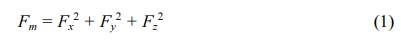
Where Fm denotes Total Machining force; Fx, Fy, Fz denotes force along x-direction, y-direction and z-direction respectively. Tool life was usually measured as the amount of tool wear produced during the successive machining of the composite material. The tool life was determined by setting the criterion at 0.3 mm of tool wear. High resolution microscope is used to measure the amount of tool wear, which in turn measures the tool life.
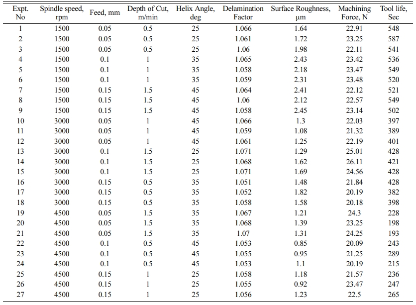
Taguchi L27 orthogonal array in design of experiments was used for planning the experiments. Taguchi method is useful in finding the optimum surface roughness, delamination factor, machining force and tool life. Taguchi’s quality loss function determines the quality characteristics by a target value and the small deviations with this target values will results in losses. The four cutting parameters viz., spindle speed, feed, depth of cut and helix angle of the end mill cutter were con- sidered for the experimental investigations. The responses selected for this study includes; surface roughness, delamination factor, machining force and tool life. The responses were measured during each experiment and their values were recorded. Total of 27 experiments were conducted and the experimental data are shown in the Table 1
Mathematical modelling
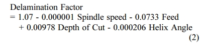
The relationship of the responses with the machining parameters were developed here by regression analysis. The regression equation for Delamination Factor, Surface Roughness, Machining Force and Tool Life were determined and given beow;
Effect of machining parameters on the Delamination factor
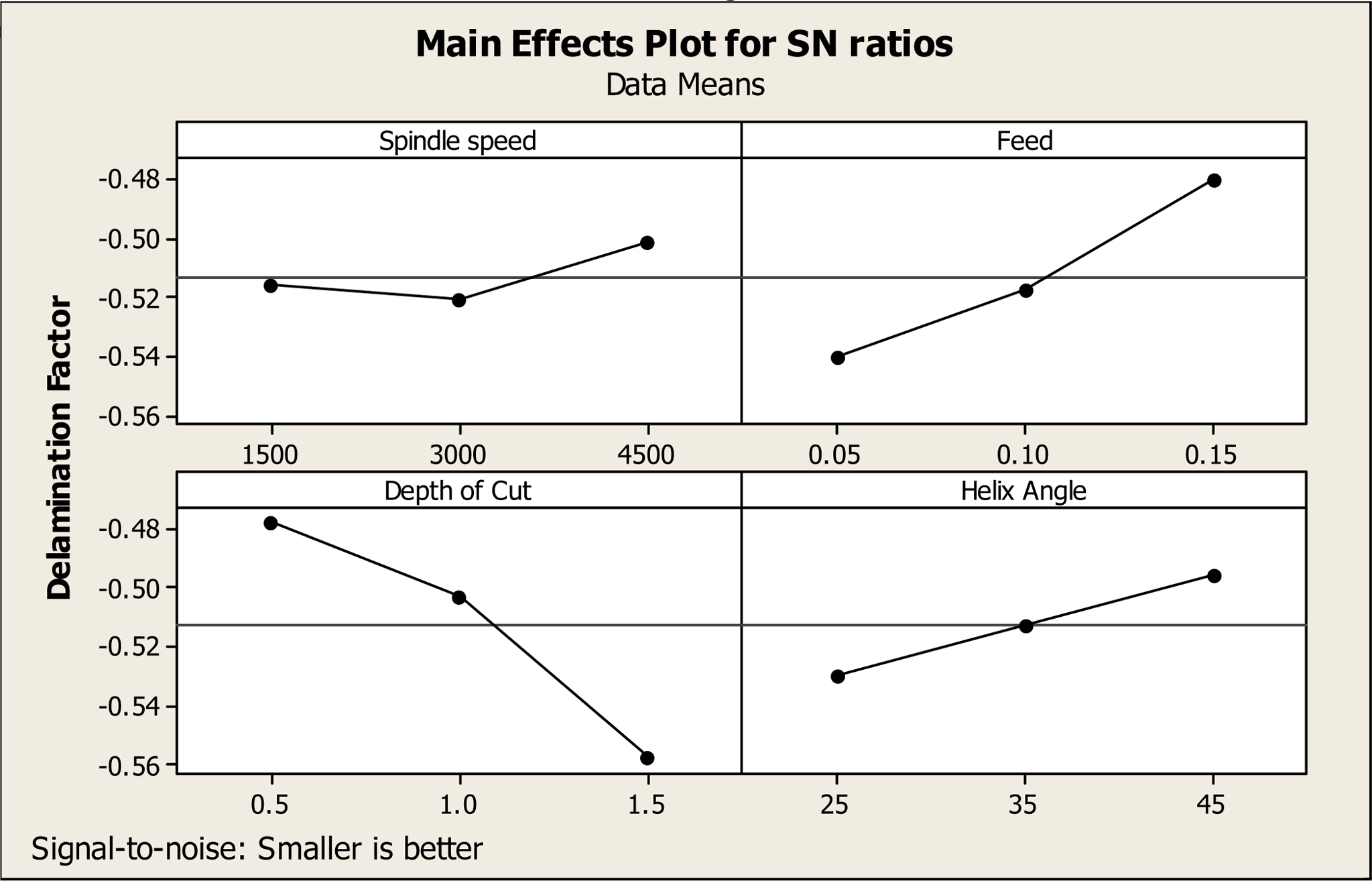
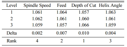
The delamination factor model was obtained by non-linear regression analysis and it is shown in Equation (2). The R-square value was estimated as 81%, which states the adequacy of the model and it is desirable for the prediction of the delamination factor of the composite materials. Table 2 shows the Analysis of Variance (ANOVA) for delamination factor during machining of the composite material using an end mill cutter in a CNC milling machine. It is observed that the percentage of contribution of depth of cut was 47.71% followed by feed with a percentage of contribution of 26.2%. Taguchi analysis of delamination factor was carried out and the response table for means for delamination factor is given in Table 3. It is noted that the depth of cut is dominant factor followed by feed, helix angle and spindle speed. The main effects plot for signal to noise ratio for the delamination factor is presented in Fig. 1, which describes the effect of delamination factor with respect to the cutting process parameter, viz., spindle speed, feed, depth of cut and helix angle. It is observed that as the feed increases, the delamination factor also increases gradually. Also it is seen that with increase in depth of cut, the delamination factor decreases to a certain extent. The delamination factor decreases to a very small extent with increase in spindle speed and then increases gradually with increase in spindle speed. Also it was noted that with increase in helix angle, the delamination factor also increases to a greater extent.
Effect of machining parameters on the Surface Roughness
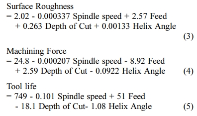
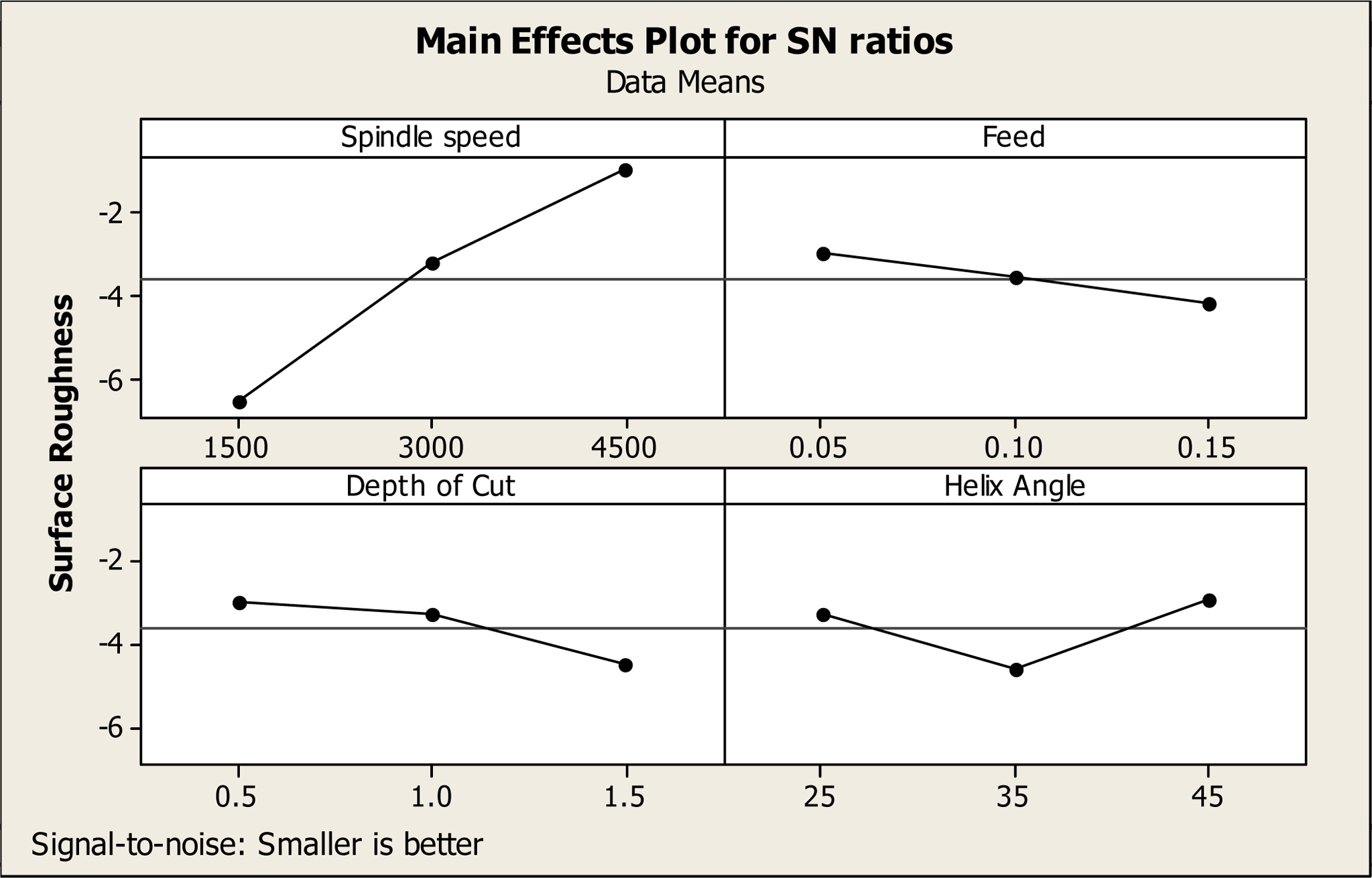
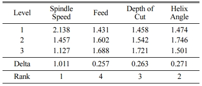
The Surface roughness model obtained by non-linear regression analysis is shown in Equation (3). The R-square value was estimated as 92.95%, which states the adequacy of the model and it is desirable for the prediction of the surface roughness of the composite materials. Table 4 shows the Analysis of Variance (ANOVA) for surface roughness during machining of the composite material using an end mill cutter in a CNC milling machine. It is observed that the percentage of contribution of spindle speed was 76.42%. However, the percentage of contribution of feed, depth of cut and helix angle were 4.91%, 5.19% and 6.41% respectively and they are very closer to each other. Taguchi analysis of the surface roughness was carried out and the response table for means for surface roughness is given in Table 5. It is observed that the spindle speed is the most dominant factor followed by helix angle, depth of cut and feed. The main effects plot for signal to noise ratio for the surface roughness is shown in Fig. 2, which describes the effect of surface roughness with respect to the cutting process parameter, viz., spindle speed, feed, depth of cut and helix angle. It is observed that as the spindle speed increases the surface roughness also increases gradually. Also it is seen that as the depth of cut increases, the surface roughness decreases to a certain extent. The increase in spindle speed will result in decrease in surface roughness and with increase in helix angle, the surface roughness increases to a certain extent.
Effect of machining parameters on the Machining force
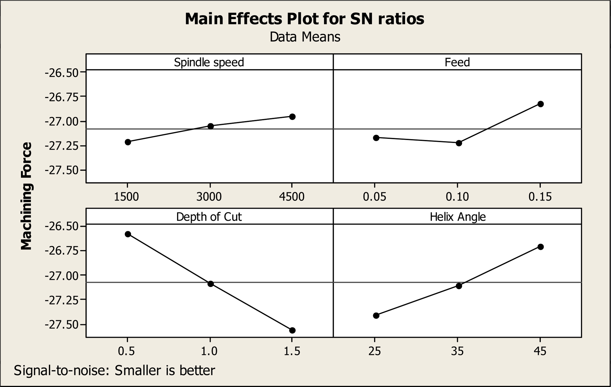
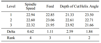
The machining force model during end milling of the composite material obtained by non-linear regression analysis is shown in Equation (4). The R-square value was estimated as 86.7%, which states the adequacy of the model and it is desirable for the prediction of the machining force of the composite materials. Table 6 shows the Analysis of Variance (ANOVA) for machining force during machining of the composite material using an end mill cutter in a CNC milling machine. It is observed that the percentage of contribution of Depth of cut was 48.95% and it is a dominant factor followed by helix angle which contributes 24.98%. Taguchi analysis of the machining force was carried out and the response table for means for machining force is given in Table 7. It is observed that the depth of cut is the most dominant factor followed by helix angle, feed and depth of cut. The main effects plot for signal to noise ratio for the machining force is shown in Fig. 3, which describes the effect of machining force with respect to the cutting process parameter, viz., spindle speed, feed, depth of cut and helix angle. It is observed that as the spindle speed and helix angel increases, the machining force also increases gradually. Also it is seen that the machining force decreases with increase in depth of cut. The machining force decreases with increase in feed up to certain extent and then increases gradually.
Effect of machining parameters on the Tool Life
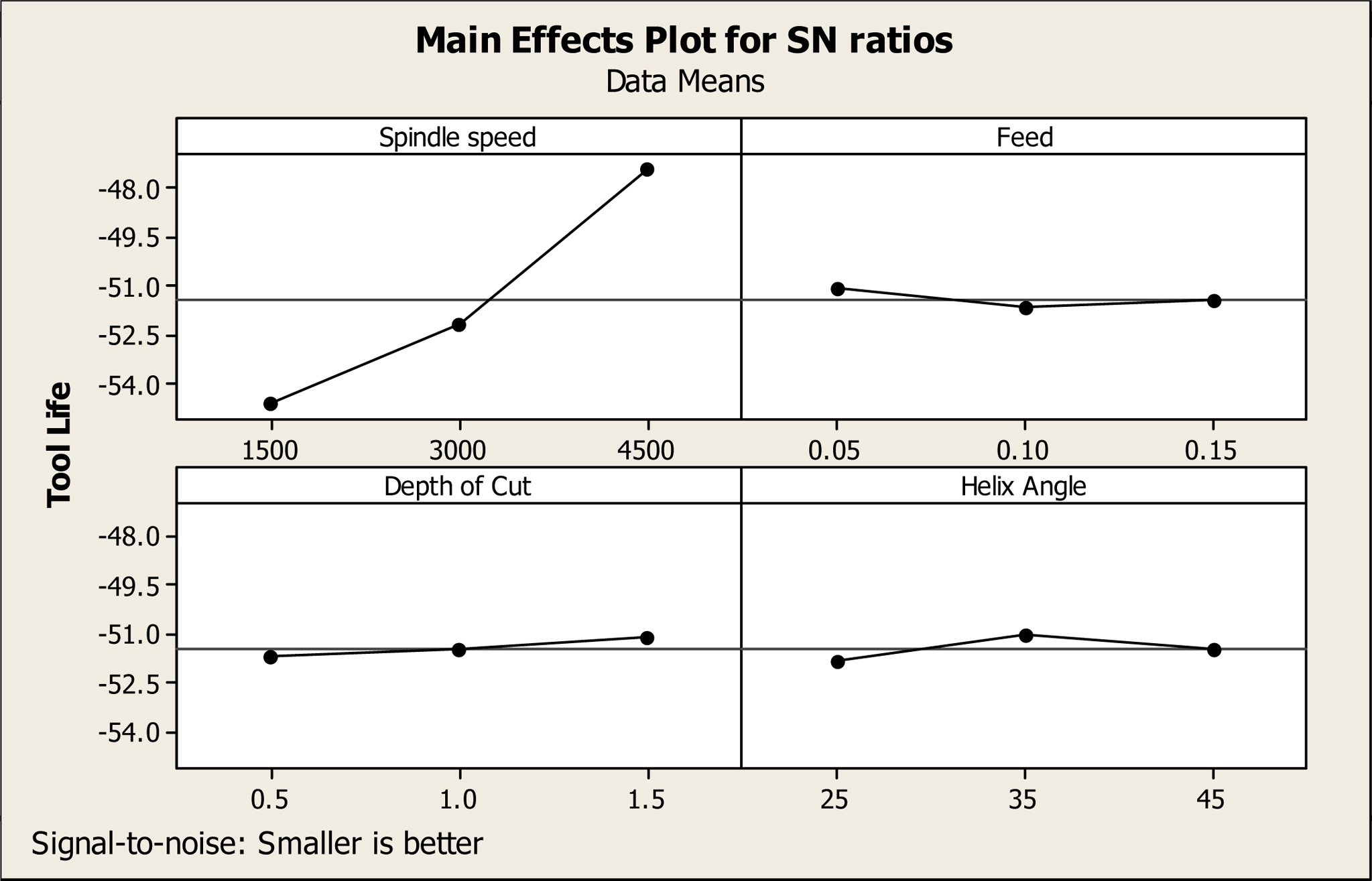
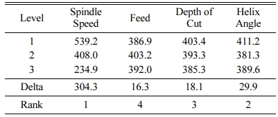
The Tool life model of the composite material obtained by non-linear regression analysis is shown in Equation (5). The R-square value was estimated as 98.18%, which states the adequacy of the model is adequate and it is desirable for the prediction of the tool life of the composite materials. Table 8 shows the Analysis of Variance (ANOVA) for tool life during machining of the composite material using an end mill cutter in a CNC milling machine. It is observed that the percentage of contribution of spindle speed was 96.56% was dominant. Taguchi analysis of the tool life was carried out and the response table for means for tool life is given in Table 9. It is observed that the spindle speed is the most dominant factor followed by depth of cut, feed and helix angle. The main effects plot for signal to noise ratio for the tool life is shown in Fig. 4, which describes the effect of tool life with respect to the cutting process parameter, viz., spindle speed, feed, depth of cut and helix angle. It is observed that as the spindle speed increases, the tool life also increases gradually. Also it is seen that with increase in depth of cut and helix angle, the tool life increases to a certain extent.
|
Fig. 1 Main effects plots for SN ratio for Delamination factor. |
|
Fig. 2 Main effects plots for SN ratio for Surface Roughness. |
|
Fig. 3 Main effects plots for SN ratio for Machining force. |
|
Fig. 4 Main effects plot for SN ratio for Tool Life. |
|
Table 2 ANOVA - Delamination Factor |
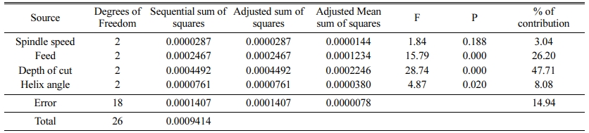
S = 0.00285169 R-Square = 81.0% R-Square(adjusted) = 77.5% |
|
Table 4 ANOVA - Surface Roughness |
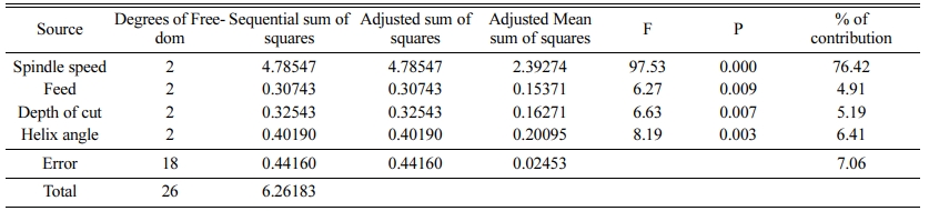
S = 0.156631 R-Square = 92.95% R-Square(adjusted) = 89.81% |
|
Table 6 ANOVA - Machining Force |
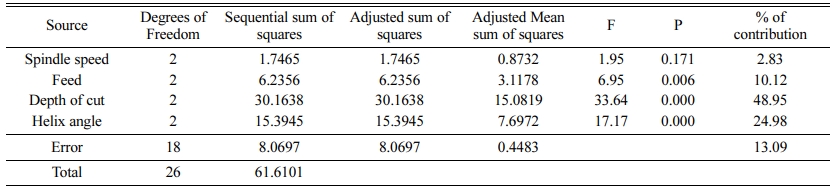
S = 0.669563 R-Square = 86.90% R-Square(adjusted) = 81.08% |
|
Table 8 ANOVA - Tool life |
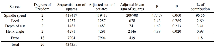
S = 20.9550 R-Square = 98.18% R-Square(adjusted) = 97.37% |
In this work, the composite substances were fabricated by way of hand layup method. Taguchi L27 orthogonal array in design of experiments was used for planning the experiments. The responses were measured during each experiment and their values were recorded. The regression equation for surface roughness, delamination factor, machining force and tool life were obtained. Taguchi analysis was carried out for delamination factor and it is observed that the percentage of contribution of depth of cut was 47.71% followed by feed with a percentage of contribution of 26.2%. Also by Taguchi analysis for surface roughness, it is observed that the percentage of contribution of spindle speed was 76.42%. However, the percentage of contribution of feed, depth of cut and helix angle are 4.91%, 5.19% and 6.41% respectively and they are very closer to each other. Taguchi analysis for machining force reveals that the percentage of contribution of Depth of cut was 48.95% and hence a dominant factor in optimizing the machining parameters for delamination factor and machining force and it is followed by helix angle which contributes 24.98%. Taguchi analysis for tool life observes that the percentage of contribution of spindle speed was 96.56% which is observed to be the dominant factor for optimizing the machining parameters for surface roughness and tool life.
- 1. O.H. Kwon and M. G. Jenkins, KSME Int. J. 16[9] (2002) 1093-1101.
-

- 2. C. Elanchezhian, B.V. Ramnath, G. Ramakrishnan, M. Rajendrakumar, V. Naveenkumar, M.K. Saravanakumar, Mater. Today: Proc. 5[1] (2018) 1785–1790.
-
- 3. W. Ouarhim, N. Zari, R. Bouhfid and A.E. Kacem Qaiss, in “Mechanical and Physical Testing of Biocomposites, Fibre-Reinforced Composites and Hybrid Composites” (Woodhead Publishing, 2019) p.43-60.
-
- 4. A. Shahzad, in “Mechanical and Physical Testing of Biocomposites, Fibre-Reinforced Composites and Hybrid Composites” (Woodhead Publishing, 2019) p.215-239.
-
- 5. P.K. Bajpai, K. Ram, L.K. Gahlot, V.K. Jha, Mater. Today: Proc. 5[2] (2018) 8699–8706.
-
- 6. O. Osita, O. Ignatius, U. Henry, Int. J. Eng. Technol. 7 (2016) 68-77.
- 7. N. Naresh, K. Rajasekhar, and P.V. Reddy, IOSR JMCE. 6[1] (2013) 102-111.
-
- 8. A.I. Azmi, R.J. Lin, and D. Bhattacharyya, Int. J. Adv. Manuf. Technol. 64[1-4] (2013) 247-261.
-
- 9. J.S. Pang, M.N.M. Ansari, O.S. Zaroog, M.H. Ali, and S.M. Sapuan, HBRC. J. 10[2] (2014) 138-144.
-
- 10. V. Kavimani, K.S. Prakash, T. Thankachan, Compos. B. Eng. 167 (2019) 621-630.
-
- 11. S. Gopalakrishnan, and N. Murugan, Compos. B. Eng. 43[2] (2012) 302-308.
-
- 12. M. Seeman, G. Ganesan, R. Karthikeyan and A. Velayudham, Int. J. Adv. Manuf. Technol. 48[5-8] (2010) 613-624.
-
- 13. M.P. Jenarthanan and R. Jeyapaul. Int. J. Eng. Sci. Technol. 5[4] (2013) 22-36.
-
- 14. K. Palanikumar, S. Prakash and K. Shanmugam, Mater. Manuf. Process. 23[8] (2008) 858-864.
-
- 15. C. R. Dandekar and Y. C. Shin, Int. J. Mach. Tools Manuf. 57 (2012) 102-121.
-
- 16. R. Vinayagamoorthy, I.V. Manoj, G. Narendra Kumar, I. Sai Chand, G.V. Sai Charan Kumar and K. Suneel Kumar, J. Mech. Sci. Technol. 32[5] (2018) 2011-2020.
-
- 17. G. Wu, and J.M. Yang, Model. Simul. Mater. Sci. Eng. 13[3] (2005) 413.
-
- 18. L. Dvorkin, V. Zhitkovsky, Y. Ribakov, O. Bordiuzhenko and A. Stepanuk, Rev. Romana Mater. 49[3] (2019) 361-369.
- 19. M. Srinivasan, S. Ramesh, S. Sundaram and R. Viswanathan, J. Ceram. Process. Res. 22[3] (2021) 345-355.
-
- 20. Y.M. Kin, J.H. Kwon, S.H. Kang, J.H. Jung, P.J. Kim and K.J. Lim, J. Ceram. Process. Res. 13[S2] (2012) S211-S214.
- 21. G.S. Krishnan, L.G. Babu, R. Pradhan and S. Kumar, Mater. Res. Express. 7[1] (2019) 015102.
-
- 22. E.N. Obika, C.H. Achebe, J.L. Chukwuneke, O.N. Ezenwa, Adv. Mech. Eng. 12[7] (2020) p.1687814020947611
-
 This Article
-
2021; 22(6): 731-738
Published on Dec 31, 2021
- 10.36410/jcpr.2021.22.6.731
- Received on Sep 13, 2021
- Revised on Oct 6, 2021
- Accepted on Oct 9, 2021
Services
- Abstract
introduction
materials and methods
experimental methodology
results and discussion
conclusion
- References
- Full Text PDF
Shared
Correspondence to
- Thirumalai Ramanathan
-
Professor, Mechanical Engineering, Dr.N.G.P. Institute of Technology, Coimbatore, India
Tel : +91 9843240635 - E-mail: vkrthirumalai@gmail.com
Clean-Energy Research Institute(CRI), Hanyang University, 222, Wangsimni-ro, Seongdong-gu, Seoul, 04763, Korea
E-mail: jcpr@hanyang.ac.kr