


- Crystallization behavior of MgO-Al2O3-SiO2 glass-ceramics prepared by directly heat-treating of laterite ore smelting slag
Ning Gao, Yaxu Chen, Chengyu Wang, Yanling Guo* and Jieyu Zhang
State Key Laboratory of Advanced Special Steel, Shanghai Key Laboratory of Advanced Ferrometallurgy, School of Materials Science and Engineering, Shanghai University, Shanghai 200444, China
This article is an open access article distributed under the terms of the Creative Commons Attribution Non-Commercial License (http://creativecommons.org/licenses/by-nc/4.0) which permits unrestricted non-commercial use, distribution, and reproduction in any medium, provided the original work is properly cited.
In this paper, we proposed a novel method to prepare MgO-Al2O3-SiO2 (MAS) glass-ceramics through direct heat treatment with the slag of laterite ore. First, the Ni-Fe alloy and slag glass were prepared simultaneously by this method, and the yield rate of Ni-Fe alloy was up to 95.69%. Then, the MAS glass-ceramics can be obtained by direct heat-treating for the slag glass. The energy consumption of glass-ceramics production was much lower than that in traditional method to make full use of the thermal energy of the molten slag. The crystallization behavior of the glass-ceramics was investigated by XRD, DSC and FESEM. The results demonstrate that many phase-separated droplets appear in the slag glass. During the heat treatment, the phase-separated droplets as favorable nucleation sites to inducing crystallization. The crystallinity and crystallite size of the samples exhibits an increasing tendency with the increase of heat treatment temperature and time.
The crystalline phases of glass-ceramics were two different compositions magnesium aluminum silicates (MgAl2Si4O12 and (Mg,Al)SiO3). The activation energies of the slag glass were calculated by Kissinger and Ozawa method, which were 308.81 and 309.36 kJ·mol-1, respectively. And the crystallization mechanism of the glass-ceramics was dominated by both the surface crystallization and bulk crystallization with one-dimensional growth.
Keywords: Slag of laterite ore, Droplet phase separation, Crystallization, Glass-ceramics
Glass-ceramics are multi-phase composites containing microcrystalline phases and glass phases. They are made from the basic glass through crystallization heat treatment [1, 2]. Industrial solid wastes such as blast furnace slags, fly ash, BOF slag, mud resulting from hydrometallurgical processing, granite waste and mixtures of different solid wastes are widely used in the preparation of glass-ceramics [3-13]. The glass-ceramics that prepared from industrial wastes have excellent mechanical properties and good chemical resistance and have a great significance to industrial applications and environmental protection. Therefore, it has become the focus of the comprehensive utilization of slag [14-17].
The slag of laterite ore is produced during the process of nickel-iron alloy smelting from laterite ores and is a valuable resource that can be recycled and utilized containing SiO2, Al2O3 and MgO. With the rapid growth in the demand for Ni-Fe alloy, the com- prehensive utilization of slag has gradually attracted the attention of researchers and using this slag to prepare MAS glass–ceramics is a promising approach[18-20].
At present, most studies about the comprehensive utilization of slag focus on the second treatment of slag after the completion of the smelting process. In general, some chemical reagents or other types of solid waste are added to the original slag to adjust its com- position, and then the slag glass-ceramics are obtained after high-temperature melting and heat treatment [21, 22]. However, the energy consumption and cost of this traditional treatment were very high. In contrast, the method of preparing glass-ceramics by direct heat treatment with the slag of laterite ore is more econo- mical and environmentally friendly. This method avoids not only the addition of substances in the process of alloy smelting and slag glass-ceramic production but also the melting and reheating process of the slag. However, until now, there have been only a few reports on glass-ceramic production by direct heat treatment with the slag of laterite ore [23]. The crystallization behavior and crystallization kinetics of the resulting glass-ceramics have not been fully investigated.
In the present study, we put forward a new method for preparing MAS glass-ceramics through direct heat treatment with the slag of laterite ore. The crystallization behavior and kinetics of the glass-ceramics were in- vestigated by differential scanning calorimetry (DSC), field-emission scanning electron microscopy (FESEM) and X-ray diffraction (XRD).
Materials and experimental procedure
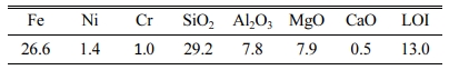
The laterite ore (China BaoWu Steel Group Corporation Limited) was mixed with an excess of premium grade pure carbon powder (Sinopharm Chemical Reagent Co., Ltd., China). The composition of laterite ore is shown in Table 1. A tablet press was used to apply a pressure of 10 MPa to the mixed material to turn it into a cylinder with a diameter of 50 mm to 10 mm in height. After that the material was placed in a corundum crucible and melt-reduced in a horizontal resistance furnace, The protective gas was high-purity argon.
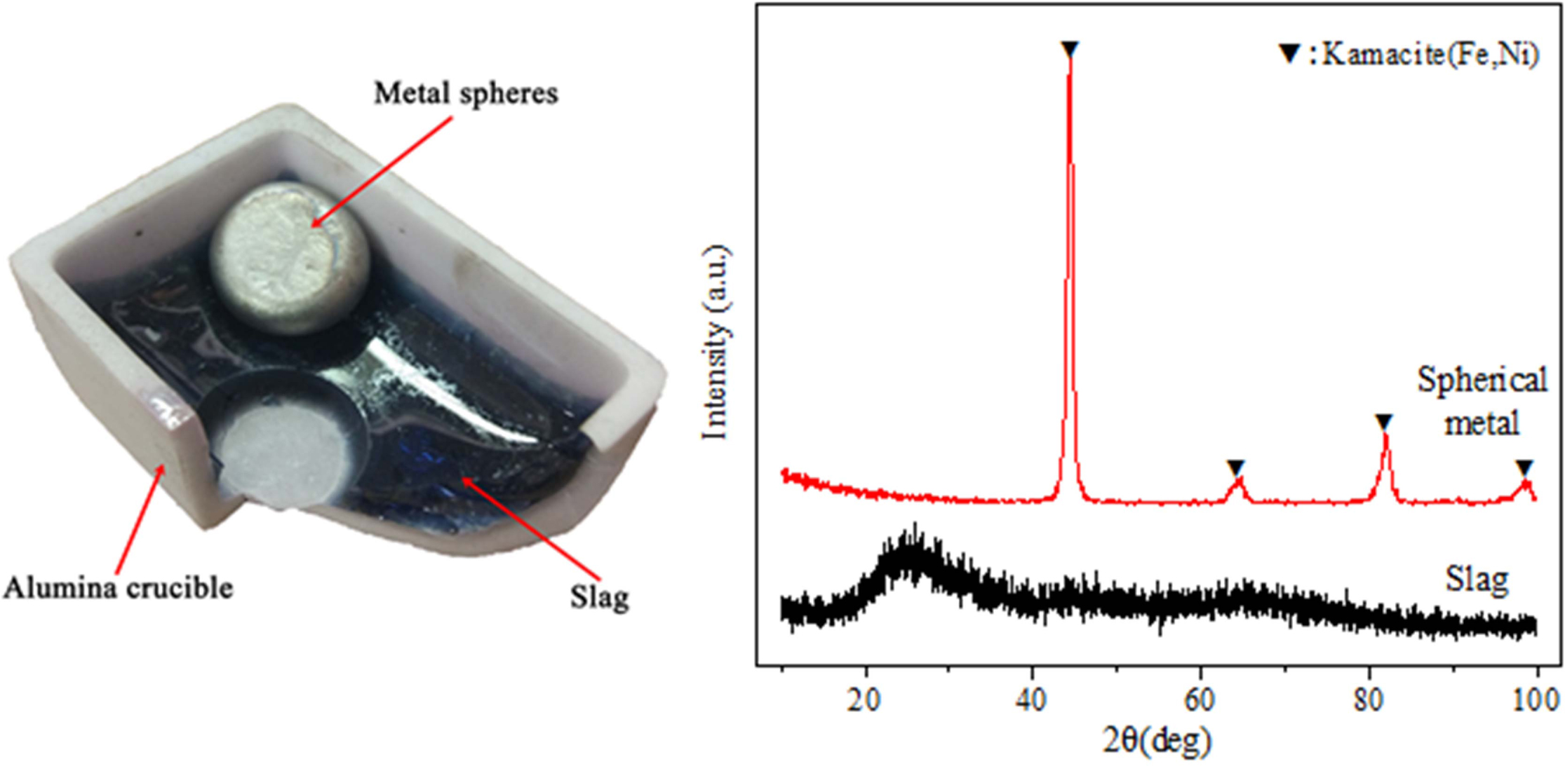
In order to reduce the metal and obtain the Ni-Fe alloy, the sample is heated to 1200 oC and kept for one hour. In order to completely separate the slag and metal and make the liquid slag fully clarified and homo- geneous, continue to heat the sample to 1500 oC for two hours. Finally, the sample furnace was cooled to room temperature and taken out. Completely separated Ni-Fe alloy and slag glass were successfully obtained (Fig. 1).
In the current slag glass system, the relative content of MgO is up to 20.3 wt.%, and a small amount of Cr2O3 (0.78 wt.%) and Fe2O3 (0.85 wt.%) also exist. Huijuan, W [24] and Rawlings, R have pointed out that these oxides can promote the crystallization of slag glass. So, in this study, a single-stage heat treatment was used as an effective method for preparing the glass-ceramics. For the purpose of studying the crystallization behaviors of glass-ceramics at different temperatures and times, combining the DSC analysis results the slag glass was heat-treated at 930-1020 oC for different times (15-60 min), respectively.
Characterizations
Differential scanning calorimetry (DSC, Model-DSC404C, NETZSCH, Germany) was applied to in- vestigate the heat variations in the samples as the temperature increased. The samples (15 ± 1 mg) was placed in a corundum crucible from ambient tempera- ture to 1400 oC in Ar, and using Al2O3 as a reference material, at heating rates of 10, 15, 20 and 25 oC/min.
In order to characterize the sample, the surfaces of the sample was chemically etched with a 10% HF solution for 15s and then coated with a platinum layer. Microstructural characterization of the samples was performed using a field-emission scanning electron microscope (FESEM, Model-JSM6700F, JEOL, Japan) with an energy dispersive spectrometer (EDS, Model-INCA, OXFORD, UK.).
The crystalline phases of the slag and glass–ceramics were examined by X-ray diffraction (XRD, Model-D\max-2550, RIGAKU, Japan). The source was Cu-Kα (λ = l51.5406 Å), and the working voltage and tube current were 40 kV and 100 mA, respectively. The sample was scanned at an angle in the range of 10o ≤ 2θ ≤ 80o at a rate of 4 o/min.
|
Fig. 1 The slag, metal sphere and their X-ray diffraction patterns. |
Preparation and characterization of slag glass
As shown in Fig. 1, the laterite ore after the melting-reduction and cooling showed two different phases: the slag and metal spheres.
The XRD analysis for original slag and metal spheres
As shown in Fig. 1, the XRD pattern of the slag has typical glassy state amorphous protrusions in the range of 15o ≤ 2θ ≤ 35o. According to the characteristic diffraction peaks, it can be seen that the composition of the metal spheres is the kamacite phase (PDF number: 37-0474). The two different phases are slag glass and Ni-Fe alloy. what' s more, the average yield of Ni-Fe alloy is 27.1 g per 100 g of laterite, and the average yield rate is 95.69%.
Microstructure of slag glass
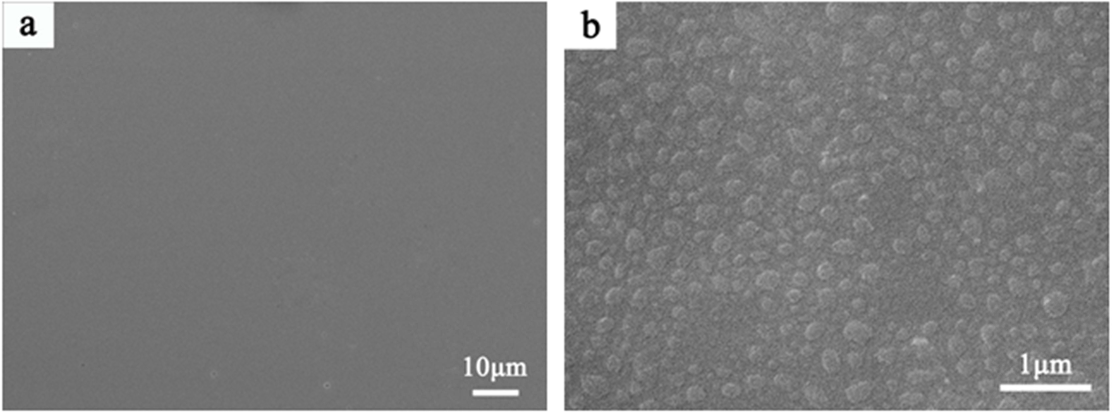
As shown in Fig. 2(b), many phase-separated droplets with a diameter of 200~300 nm are observed in slag glass. The emergence of phase-separated droplets means the enrichment of certain elements, which changes the chemical composition of phase separation and matrix, and leads to the difference of viscosity between them. And it will affect the manner in which phase separation induces crystallization [25].
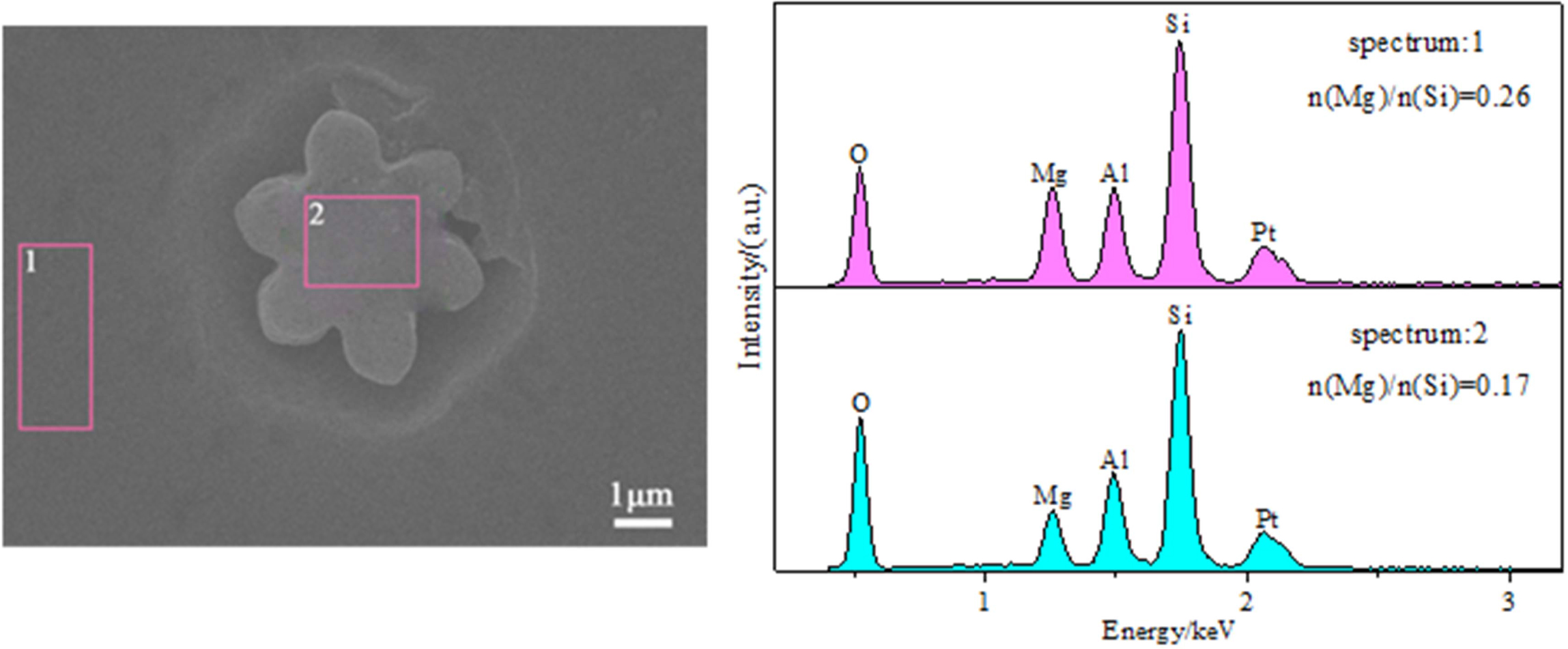
The compositions of the matrix and droplet induced crystals were characterized by EDS. The results of the EDS analysis of the micro-regions are shown in Fig. 3.
It can be seen from Fig. 3 that the enrichment of silica occurs in the crystals induced by the droplet phase and its magnesia content is lower. Thus, many continuous silicate nets can be established in the silica-rich amorphous droplets. Mg2+ (r = 0.065 nm; the single bond strength of Mg-O = 155 kJ/mol), as a net gap ion in the glass net structure, has a great influence on the adjustment of the glass net structure and the manner of phase separation to induce crystallization. In the glass net structure, MgO can provide an O2- ion to destroy the [SiO] net structure, and Mg2+ can fill in the voids or gaps of the disordered net structure. Therefore, MgO breaks the chain structure of the [SiO4] tetrahedron in the Mg-rich matrix glass, causing the viscosity of the glass matrix to decrease, the ions to easily diffuse, and the Ostwald growth (with the interfacial energy as the driving force, small particles are ablated, large particles grow, the specific mass per unit area decreases, and the total free energy of the system decreases) appears in the silica-rich droplets during the subsequent heat treatment.
Thermal analysis of slag glass
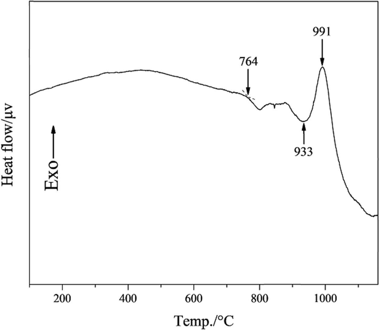
Fig. 4 shows the DSC curve of the slag glass. The slag glass transition temperature is 764 oC, the transition of atoms in slag glass and the adjustment of glass network structure at this temperature. the onset crystallization temperature and the crystallization peak temperature are 933 o and 991 o.
Crystallization behavior of the glass-ceramics
Heat treatment temperature
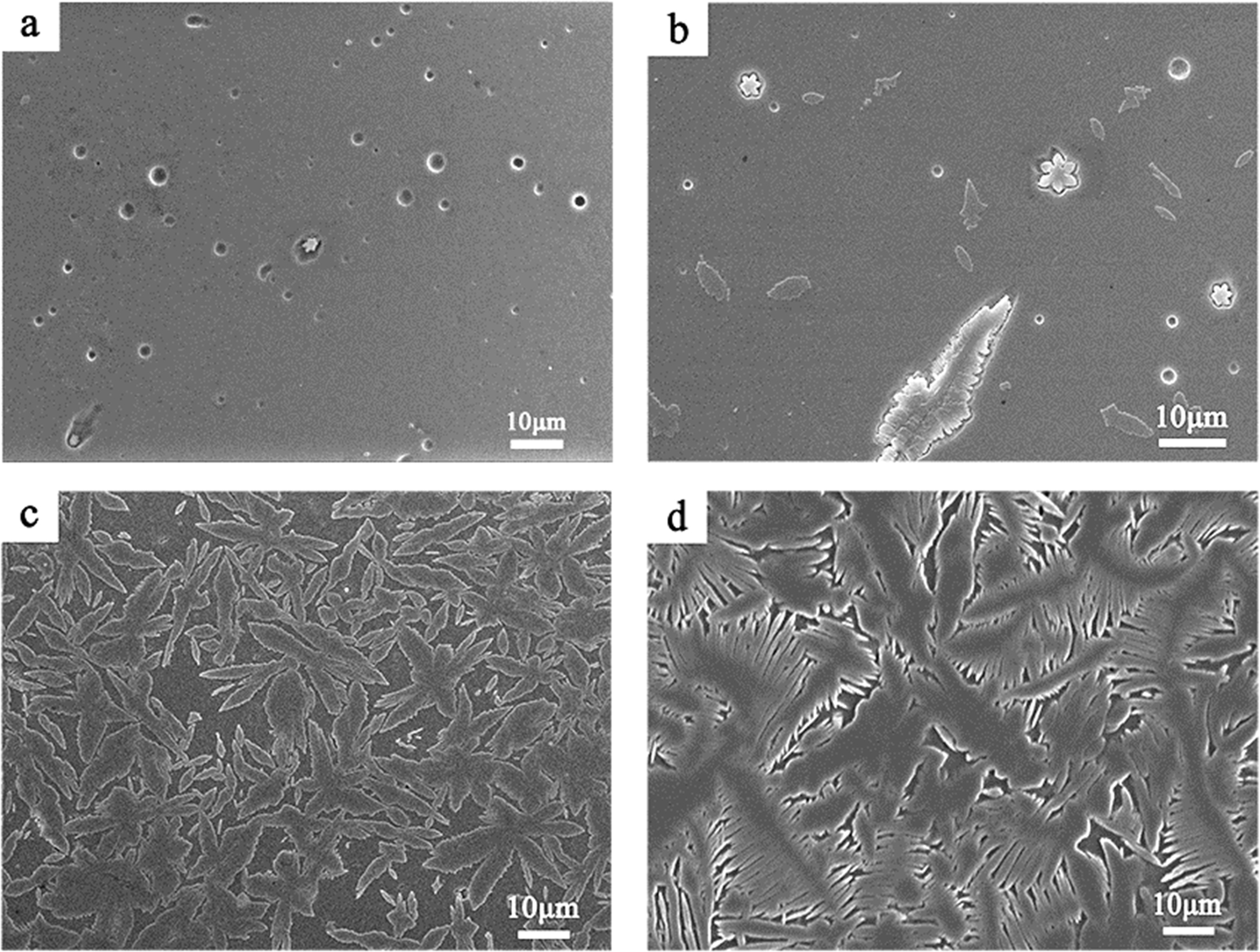
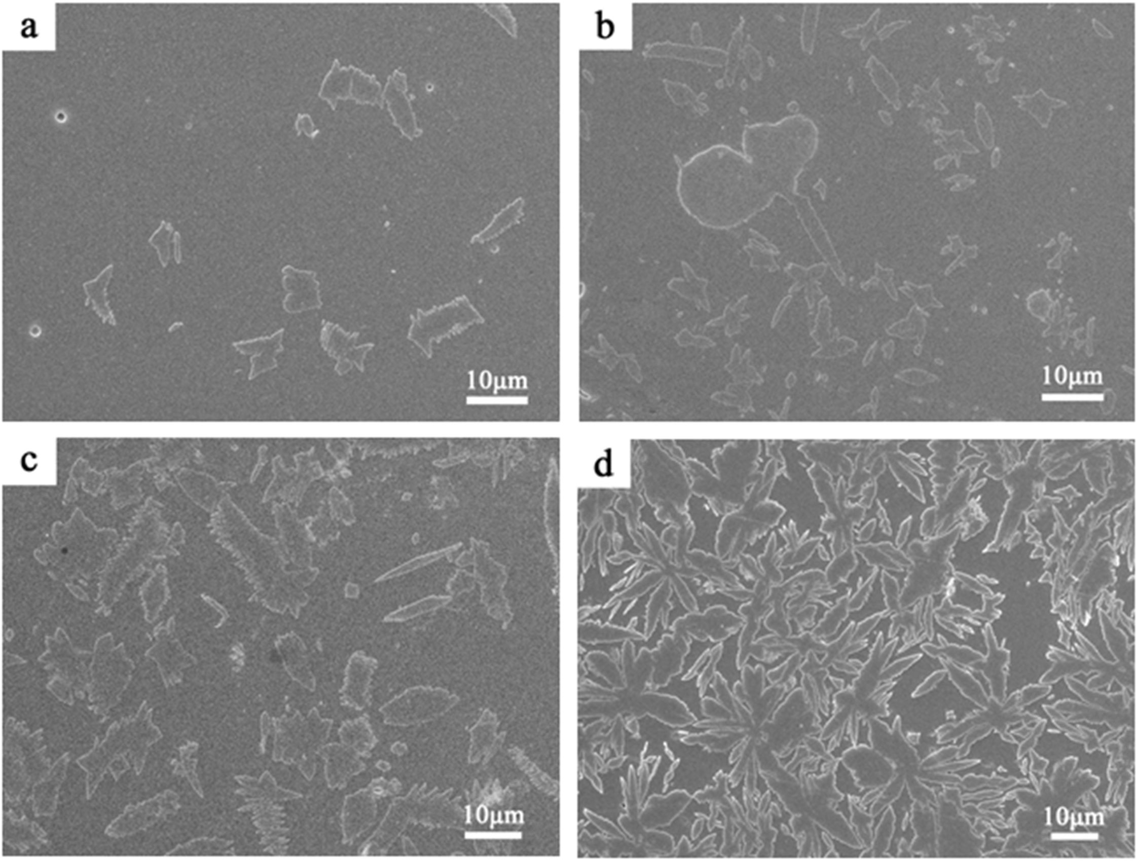
Fig. 5 shows the SEM micrographs of the samples heat treated at different temperatures for 1 h. When the heat treatment temperature is 930 or 960 oC, the number of crystals is smaller and the crystallinity of the sample is lower. Some spherical pores of about 1.5 μm appeared in the samples. This may be due to that some of the grains are washed out by ultrasonic during the ultrasonic cleaning of the polished sample after etching in the HF solution. With the heat treatment temperature increase to 990 oC, the number and size of the crystals in the sample significantly changed. At this temperature, the viscosity of the glass is greatly reduced, and the ion diffusion rate is increased. The nucleation rate and growth rate of the crystals increase, resulting in a larger number and volume of crystals. When the heat treatment temperature was 1020 oC (Fig. 5d), the secondary growth of dendrites in the snowflake or platelet-like crystals appeared, and the length of the secondary dendrites was mainly in the range of 5-20 μm.
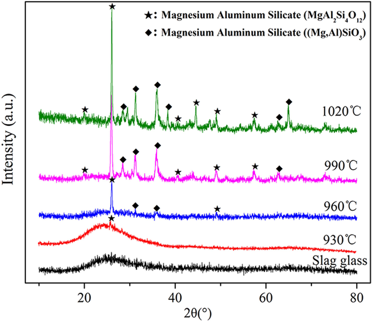
Fig. 6 shows the XRD patterns of the samples. After the heat treatment at 930 oC/1 h, typical glassy state amorphous protrusions appeared in the XRD pattern of this sample in the range of 15o ≤ 2θ ≤ 35o. Additionally, a crystalline peak of MgAl2Si4O12 (PDF number: 27-0716) appeared at 2θ = 25.902o. And the degree of the crystalline peak is relatively low, indicating that the number of crystals at this temperature is relatively small. After the heat treatment at 960 oC/1 h, the crystalline peak at 2θ = 31.294o and 35.965o indicate the appearance of another structure of magnesium aluminum silicate, (Mg,Al)SiO3 (PDF number: 350310). Therefore, two kinds of crystal phases were precipitated in the sample: MgAl2Si4O12 and (Mg,Al)SiO3. The crystallinity of the sample was calculated to be 18.41% (R = 6.94) according to the crystalline peak intensity in the XRD pattern. With the heat treatment temperature increase to 990 or 1020 oC, the type of crystalline phase in the samples did not change, but the number and intensity of the crystalline peaks obviously increased. Thus, the degree of crystallization was significantly improved. The crystallinity of the samples was calculated to be 65.63% (R = 5.37) and 81.72% (R = 6.15), respectively.
Overall, SEM images (Fig. 5) and XRD patterns (Fig. 6) demonstrate that the sample has well crystallized at 990 oC and without abnormal growth of crystals, and the crystalline phases are MgAl2Si4O12 and (Mg,Al)SiO3.
Heat treatment time
To further explore the effect of heat treatment time on the crystallization process of glass-ceramics, the slag glass was heat-treated at 990 oC for 15, 30, 45 and 60 min.
Fig. 7 shows the SEM images of the samples. With the heat treatment time increases, the phase-separated droplets continued to grow and accumulate to form an irregular flake- or rod-like structure. Eventually, snowflake- or flake-like crystals formed based on the mutual aggregation of irregular flake or rod-like structures. When the holding time increased from 45 to 60 min, the shape and quantity of the crystals in the sample changed significantly.
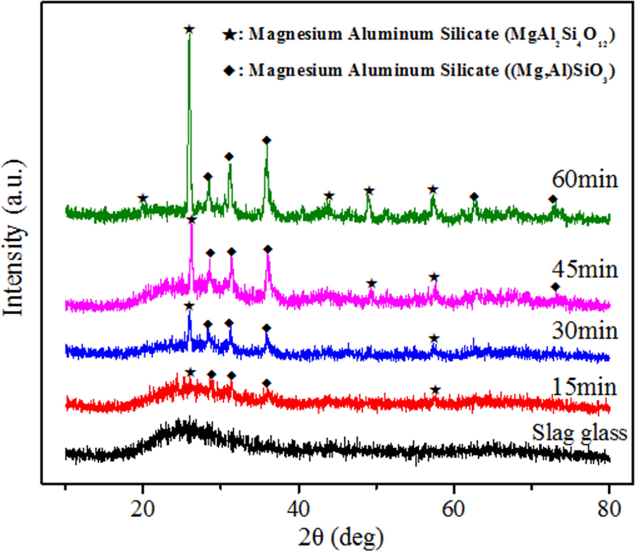
The results of the XRD patterns of the samples heat-treated at 990 oC for different times are presented in Fig. 8. The increase of heat-treatment time does not change the type of crystalline phase precipitated in the samples.
MgAl2Si4O12 (PDF number: 27-0716) and (Mg,Al)SiO3 (PDF number: 35-0310). Additionally, the intensity of the crystalline peaks in XRD patterns increases gradually, which means that the crystallinity of the samples is continuously increasing. The XRD patterns were refined and fitted to calculate the crystallinity. The value of R in the pattern fitting process was less than 6.5%.
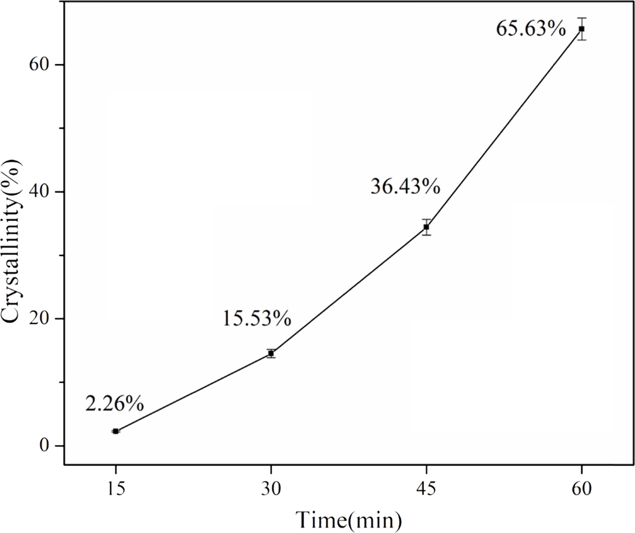
Fig. 9 reveals the crystallinity of the different samples. The crystallinity increased from 2.26% to 65.63% when the heat treatment time increased. The average crystallization rate also increased as the heat treatment time increased from 15 to 60 min. This may be due to the fact that when the heat treatment temperature is in the crystallization temperature range, the viscosity of the samples decreases over time, and the ion diffusion rate increases. Therefore, when the duration of heat treatment increases from 15 to 60 min, the crystallization rate will increase gradually.
Activation energy of crystallization and crystalliz- ation mechanism
At present, the Kissinger equation [26] and the Ozawa equation [27] are the commonly used methods for calculating the crystallization kinetic parameters of glass-ceramics. Zhongjie, W and El‐Sheikh, S [28, 29] have successfully analyzed the crystallization kinetics of slag glass-ceramics using two methods. Consequently, in this paper, the crystallization activation energy of glass-ceramics was estimated by using the Kissinger equation and the Ozawa equation, respectively.
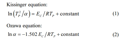
where TP is the crystallization peak temperature; α is the DSC heating rate, which is 10 oC, 15 oC, 20 oC, or 25 oC/min; EC is the crystallization activation energy (J·mol-1); and R is the gas constant (8.314 J·mol-1).
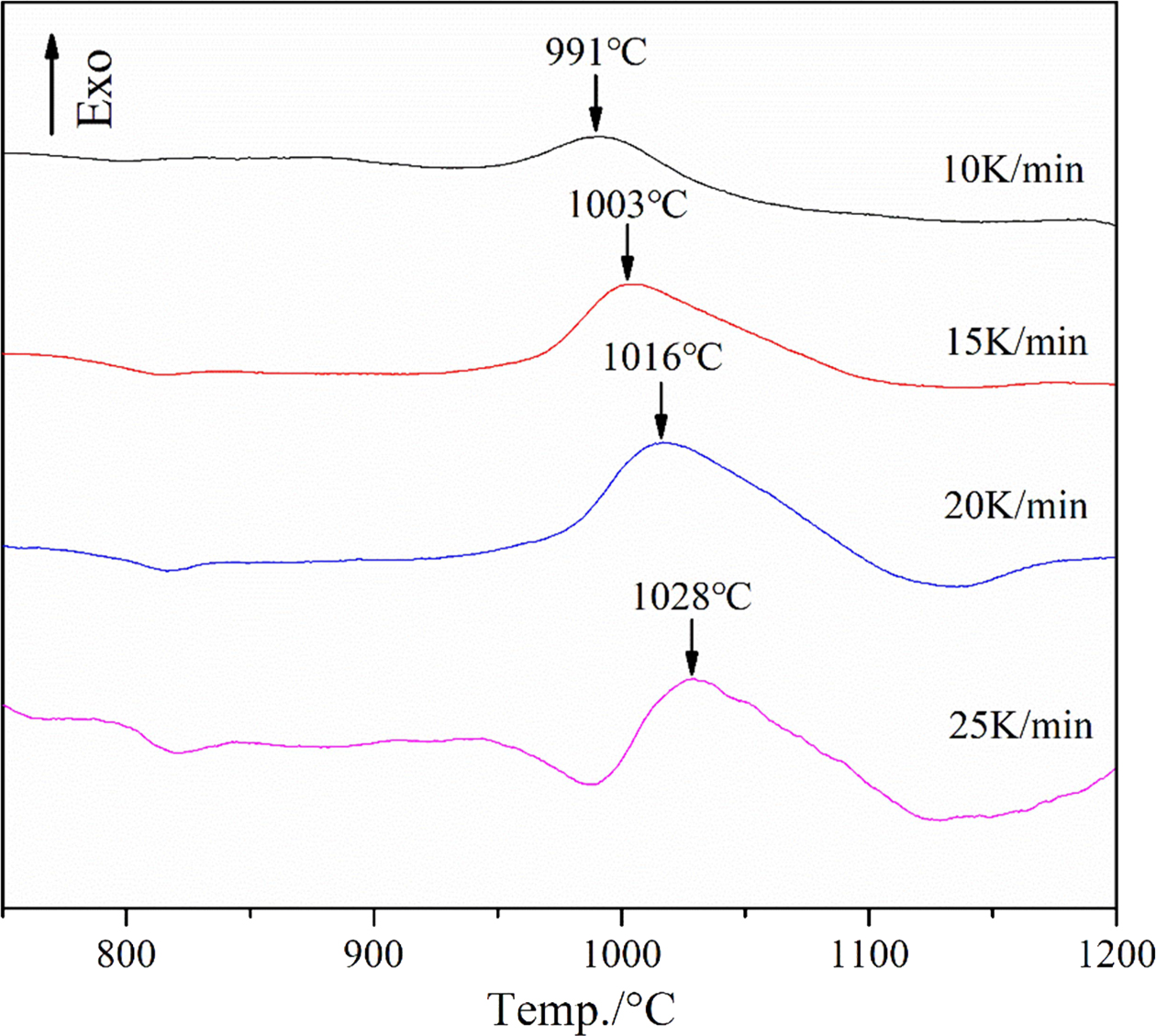
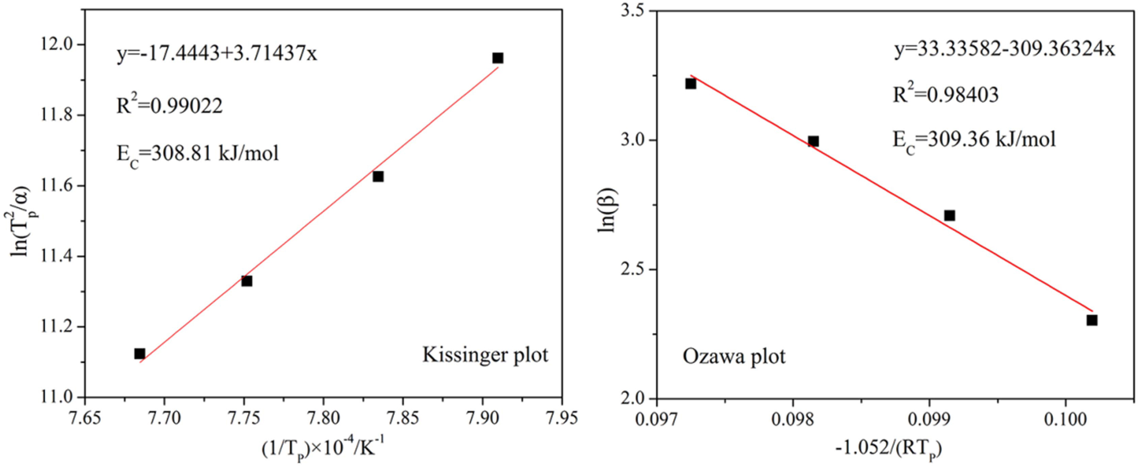
As shown in Fig. 10, the crystallization peak tem- perature(TP) clearly increases with the heating rate. The value of TP in the DSC curves at different heating rates was substituted into Eq. (1) and (2) to plot the ln (TP2/α) vs 1/TP and ln (α) vs 1/TP diagrams, and the data fit to a straight line. The result is shown in Fig. 11.
The values of crystallization activation energy for glass-ceramic calculated by Kissinger method and Ozawa method are 308.81 kJ·mol-1 and 309.36 kJ·mol-1, respectively. The results obtained by the two calcula- tion methods are very similar. As reported, the crystallization activation energies of glass-ceramics prepared from blast furnace slag [30], flash furnace nickel slag [21] and coal ash [31] are 457.5, 371.1 and 545 kJ·mol-1, respectively. By comparison, the EC of the glass-ceramic directly treated by the slag of laterite ore is smaller. In other words, the slag glass can be crystallized under low energy consumption conditions.
Subsequently, according to the calculated value of activation energy (EC), the Avrami parameter (n) can be calculated using the equation presented by Augis, J., and Bennett, J [32]:
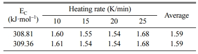
where ΔT is the width of the crystallization peak at half height. Different Avrami parameters (n) corresponded to different dimensionality of crystal growth. The value of n close to 1, 2, 3, or 4 shows that the crystallization is dominated by the surface crystallization, one-dimensional, two-dimensional, and three-dimensional growth crystallization mechanisms. The EC obtained by the Kissinger and Ozawa methods is used to calculate the Avrami parameter (n). The results are shown in Table 2.
It can be seen from Table 2 that under different heating rates, the value of n does not change signifi- cantly. The average value of the Avrami parameter n is 1.59, indicating that the mechanism of crystallization includes the surface crystallization and the bulk crystallization with one-dimensional growth.
|
Fig. 2 SEM images of the slag glass, a: ×2000; b: ×20000. |
|
Fig. 3 EDS analyses of different phase regions in the samples (in atomic percentage). |
|
Fig. 4 DSC analysis curve of slag glass. |
|
Fig. 5 SEM images of the samples (a: 930 °C/1 h, b: 960 °C/1 h, c: 990 °C/1 h, d: 1020 °C/1 h). |
|
Fig. 6 XRD patterns of the samples heat-treated at different temperatures for 1 h. |
|
Fig. 7 SEM image of images of the samples (a: 15 min, b: 30 min, c: 45 min, d: 60 min). |
|
Fig. 8 XRD patterns of the samples heat-treated at 990 oC for different times. |
|
Fig. 9 Crystallinity of slag glass after heat treatment at 990°C for different time. |
|
Fig. 10 DSC curves of the slag glass recorded at different heating rates |
|
Fig. 11 Kissinger and Ozawa plots constructed from the DSC data. |
In this study, a low-cost method for preparing MAS glass-ceramics from laterite ore was introduced. The Ni-Fe alloy and the slag glass can be simultaneously obtained by adding excess carbon powder to the laterite ore and then smelting at a high temperature. Subsequently, the slag glass is heat-treated to obtain the glass-ceramic. Furthermore, the yield rate of Ni-Fe alloy is up to 95.69%, and the slag utilization rate is 100%. Obviously, this method is more economical and environmental than conventional methods.
There is significant droplet phase separation in the slag glass, which will induce the crystal to precipitate during the subsequent heat treatment. With the tem- perature or time increases, the crystallinity of the sample is increasing, and the type of the crystal phase does not change, that is, two different structures of magnesium aluminium silicates: MgAl2Si4O12 and (Mg,Al)SiO3.
Moreover, the values of crystallization activation energy for glass-ceramic calculated by Kissinger method and Ozawa method are 308.81 kJ·mol-1 and 309.36 kJ·mol-1, respectively. Compared with other solid waste glass-ceramics, the crystallization activation energy of the samples is smaller, and the crystallization process is easier. Furthermore, the crystallization mechanism of the glass-ceramics includes the surface crystallization and the bulk crystallization with one-dimensional growth.
This work was supported by the National Natural Science Foundation of China (No. 51304131); The Independent Research and Development Project of the State Key Laboratory of Advanced Special Steel, Shanghai University (No. SKLASS 2017-Z051); and the Shanghai Science and Technology Committee (No. YDZX20173100001316).
- 1. R. Rawlings, J. Wu, and A. Boccaccini, J. Mater. Sci. 41[3] (2006) 733-761.
-

- 2. J. Deubener, M. Allix, M. Davis, A.Duran, T. Höche, T. Honma, T. Komatsu, S. Krüger, I. Mitra, R. Müller, S. Nakane, M. Pascual, J. Schmelzer, E. Zanotto, and S. Zhou, J. Non-Cryst. Solids. 501[10] (2018) 3-10.
-
- 3. J. Kang, J. Wang, J. Cheng, J. Yuan, Y. Hou, and S. Qian, J. Non-Cryst. Solids. 457[1] (2017) 111-115.
-
- 4. J. Yang, D. Zhang, J. Hou, B. He, and B. Xiao, Ceram. Int. 34[1] (2008) 125-130.
-
- 5. K. Chen, Y. Li, Y., X. Meng, L. Meng, and Z. Guo, Ceram. Int. 45[18] (2019) 24236-24243.
-
- 6. D. He, C. Gao, J. Pan, and A. Xu, Ceram. Int. 44[2] (2017) 1384-1393.
-
- 7. M-W. Choi, and S-M. Jung, Ironmak steelmak. 45[5] (2018) 441-446.
-
- 8. B. Li, Z. Zhang, W. Wu, M. Zhao, Y. Shi, IOP Conf. Ser.: Mater. Sci. Eng. 474[1](2019) 012049.
-
- 9. C. Başaran, N. Toplan, and H. Toplan, J. Therm. Anal. Calorim. 134[1] (2018) 313-321.
-
- 10. T. Toya, A. Nakamura, Y. Kameshima, A. Nakajima, and K. Okada, Ceram. Int. 33[4] (2007) 573-577.
-
- 11. H. Liu, H. Lu, D. Chen, H. Wang, H. Xu, and R. Zhang, Ceram. Int. 35[8] (2009) 3181-3184.
-
- 12. E. Ljatifi, A. Kamusheva, A. Grozdanov, P. Paunovic, and A. Karamanov, Ceram. Int. 41[9] (2015) 11379-11396.
-
- 13. A. Demirkiran, S. Yilmaz, and U. Sen, J. Ceram. Process. Res. 14[1] (2013) 51-55.
- 14. D. Tulyaganov, M. Ribeiro, and J. Labrincha, Ceram. Int. 28[5] (2002) 515-520.
-
- 15. Y. Zhao, D. Chen, Y. Bi, and M. Long, Ceram. Int. 38[3] (2012) 2495-2500.
-
- 16. W. Dang, and H-Y. He, J. Ceram. Process. Res. 21[1] (2020) 69-74.
-
- 17. J. Temuujin, U. Bayarzul, E. Surenjav, K-D. Sung, and C-Y. Ski, J. Ceram. Process. Res. 18[2] (2017) 112-115.
- 18. J. Li, D. Li, Z. Xu, C. Liao, Y. Liu, and B. Zhong, J. Clean. Prod. 179[1] (2018) 24-30.
-
- 19. X. Ma, Z. Cui, and B. Zhao, JOM. 68[12] (2016) 3006-3014.
-
- 20. F. Gu, Z. Peng, Y. Zhang, H. Tang, L. Ye, W. Tian, G. Liang, M. Rao, G. Li, and T. Jiang, Acs. Sustain. Chem. Eng. 6[4] (2018) 4880-4889.
-
- 21. M. Mingsheng, N. Wen, and W. Yali, J. Univ. Sci. Techno. B. 29[2] (2007) 168-172.
- 22. K. Zhou, Q. Zhao, and Y. Zhang, Univers. J. Mater. Sci. 5[2] (2017) 52-57.
-
- 23. X. Ma, Z. Cui, and B. Zhao, JOM-US. 68[12] (2016) 3006-3014.
-
- 24. H. Wang, B. Li, H. Lin, W. Chen, and L. Luo, Int. J. Appl. Glass. Sci. 5[4] (2014) 436-442.
-
- 25. F. Xianping and C. Quanqing J. Non-Cryst. Solids. 112[1] (1989) 232-237.
-
- 26. H. Kissinger, J. Res. U.S. Nat. Bur. Stand. 57[4] (1956) 217-221.
-
- 27. C. Păcurariu, R. Lazău, I. Lazău, R. Ianoş, and B. Tiţa, J. Therm. Anal. Calorim. 97[2] (2009) 507-513.
-
- 28. Z. Wang, W. Ni, Y. Ja, L. Zhu, and X. Huang, J. Non-Cryst. Solids. 356[31] (2010) 1554-1558.
-
- 29. S. M. El‐Sheikh, Y. M. Ahmed, E. M. Ewais, and J. F. Al‐Sharab, J. Am. Ceram. Soc. 93[7] (2010) 2082-2091.
-
- 30. A. Francis, J. Am. Ceram. Soc. 88[7] (2005) 1859-1863.
-
- 31. A. Francis, R. Rawlings, R. Sweeney, and A. Boccaccini, J. Non-Cryst. Solids. 333[2] (2004) 187-193.
-
- 32. J. Augis, and J. Bennett, J. Therm. Anal. Calorim. 13 (1978) 283-292.
-
 This Article
-
2021; 22(6): 714-721
Published on Dec 31, 2021
- 10.36410/jcpr.2021.22.6.714
- Received on Aug 13, 2021
- Revised on Oct 14, 2021
- Accepted on Oct 16, 2021
Services
- Abstract
introduction
experimental and characterization
results and discussion
conclusion
- Acknowledgements
- References
- Full Text PDF
Shared
Correspondence to
- Yanling Guo
-
State Key Laboratory of Advanced Special Steel, Shanghai Key Laboratory of Advanced Ferrometallurgy, School of Materials Science and Engineering, Shanghai University, Shanghai 200444, China
Tel : +86-136 2184 7853 - E-mail: yanling_guo@shu.edu.cn
Clean-Energy Research Institute(CRI), Hanyang University, 222, Wangsimni-ro, Seongdong-gu, Seoul, 04763, Korea
E-mail: jcpr@hanyang.ac.kr