- Designing a centrifugal atomization machine with trial manufacturing Sn powder through various rotation
Dwita Suastiyantia,*, Hari Pratomob and Abdurahman Hanafi Hamdanic
aDepartment of Mechanical Engineering, Institut Teknologi Indonesia, Puspiptek Raya Street, Tangerang Selatan, 15314 Indonesia
bPhysics Research Centre, Lembaga Ilmu Pengetahuan Indonesia, Puspiptek Raya Street, Tangerang Selatan, Indonesia, 15314, Indonesia
cDepartment of Mechanical Engineering, Institut Teknologi Indonesia, Puspiptek Raya Street, Tangerang Selatan, 15314 IndonesiaThis article is an open access article distributed under the terms of the Creative Commons Attribution Non-Commercial License (http://creativecommons.org/licenses/by-nc/4.0) which permits unrestricted non-commercial use, distribution, and reproduction in any medium, provided the original work is properly cited.
This work is intended to design a centrifugal atomization machine to create a device capable of producing Sn powder at low cost and high productivity. The material used for the centrifugal atomization machine is ST37 steel, based on the calculated material strength of the construction design. The compressive force that occured in the motor mount and secondary heater bracket is 0.86168 N/mm2. The bending stress that occured in the secondary heater bracket is 1.5625 N/mm2. The bending stress that occured in the tundish bracket amounts to 3.33 N/mm2 and is deemed safe for the construction of the centrifugal atomization machine. The powder in mesh 300 dominated the results in the various rotating disk speed of 20000 rpm and 24000 rpm. The XRD diffractogram showed the peak suitability of the powders at 15000 rpm, 20000 rpm, and 24000 rpm to match the peak of tin
Keywords: machine design, centrifugal atomization machine, Sn powder, manufacturing, research and development
Tin is a form of metal with a chemical element that has the symbol Sn (stanum) and an atomic number of 50. Tin is a malleable silvery metal, not easily oxidized by air which allows tin some rust resistant properties. The melting properties of these synthesized nanoparticles were studied by differential scanning calorimetry. The melting temperatures of Sn depend on its diameter of 81, 40, 36 and 34 nm are 226.1, 221.8, 221.1 and 219.5 oC, respectively [1].
Indonesia is one of the four largest tin producers in the world. Indonesia's own tin ore production is centered on the island of Bangka. With that said however, to meet the demands of tin powder as basic material for various industries in the country, tin is still 100% imported from other countries. This is mainly due to the lack of an industrial-scale Sn powder manufacturing equipments in Indonesia, hence why it’s still mainly imported.
Tin applications include use in food packaging, PVC pipe industrial stabilizer, and electronic component assembly. There are many applications for tin, with the utilization of tin products in the electronics sector being the most prominent. 52% of the total ingots produced in Indonesia would be processed into tin paste for soldering. In addition to soldering tin, ingots are also widely processed in the plating industry in the form of tin plates (16%) and chemical base materials (13%). Other uses of tin include the manufacture of brass and bronze (5.5%), the glass industry (2%) and other applications (11%) [2].
For this reason, it is necessary to manufacture machines that can be used to produce Sn powder that can meet the needs of the tin processing industry in Indonesia. Testing of the resulting powder from the atomization process also needs to be done in order to determine the success rate of the centrifugal atomization machine [3, 4]
Tin powder manufacture
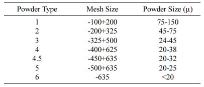
Tin cannot be directly used in the form of solder paste. The tin must first be converted into powder form, so that it can then be used in the manufacture of solder paste. Table 1. shows the standard size of tin powder used in the manufacture of solder paste.
Theoretically, to produce Sn powder, several methods of tin powder can be used, namely mechanical (Mechanical or Pulverization), chemical (Chemical), electrolytic (Electrolytic Deposition) and atomization (Atomization). In the design of this machine, it was chosen to use the centrifugal atomization method for the manufacture of Sn powder. The reason for this method is because it only requires low cost for the atomization process and besides that, it does not require further processing of the fluid to be atomized [5]. For the process of making this atomization tool, it is necessary to calculate the strength of the centrifugal atomization machine con- struction and test the manufacturing of Sn powder.
Metal atomization is a method of creating metal powders, by heating the metal to its melting point after which the melted molten metal is flowed through a nozzle. After the molten metal comes out of the nozzle, the atomization process is carried out in various ways, namely through high pressure water spray, pressurized gas spray, or by using a centrifugal dish.
Water atomization is a commonly used method for producing metal powders having a melting point below 1600 oC. High pressure water is sprayed directly on the molten metal, forcing disintegration of the molten metal and rapid solidification occurs.
The process of water atomization occurs when the molten metal from the nozzle collides with the water sprayed from the sprayer. The atomization process using water is greatly affected by the pressure and angle of spraying the water used to break up the molten metal. The powder formation processes that may occur in the water atomization process are cratering, splashing, stripping and bursting.
Gas atomization process can be classified into two types, that is using compressed air or using inert gas. The compressed air process is used for metals that have a low liquid temperature and the metal is not reactive to its oxidants, such as lead and tin. The inert gas process is conducted by namely adding a certain gas into the atomization chamber. This technique is used for metals that have high liquid temperatures and are very reactive. Some of the inert gases commonly used in the gas atomization process are nitrogen, argon and helium. The molten metal flowing through the nozzle hole will be sprayed by pressurized gas through the gas nozzle, so that the liquid metal will decompose and then freeze in the form of metal powder. In this gas atomization method, the liquid metal stream must be superheated, which causes the solidification time of the powder after the atomization process to become longer. The factors that affect the production of metal powders in the gas atomization process are: the type of gas used, the viscosity of the molten metal, the temperature of the molten metal, the type of alloy, the flow rate of the molten metal, the gas pressure, the gas velocity, the flow rate of the gas, the viscosity of the gas, the geometry of the nozzle. and the gas temperature. The amount of gas pressure will affect the size of the powder, with smaller powders able to be produced by increasing the pressure of the gas exiting the nozzle. Besides the high gas pressure, the low viscosity of the liquid metal will also cause the resulting powder to be smaller. The factor that also influences the success of the powder manufacturing process using the gas atomization method is the gas nozzle design. The gas nozzle must be able to radiate gas evenly throughout the atomization area.
Centrifugal atomization can be defined as the process of breaking up molten metal that falls into a rotating disk by rotating it at high speed, so that metal powder is formed. This centrifugal atomization utilizes the cen- trifugal force generated from the rotating disk which is rotated by the motor spindle. The simple concept of centrifugal force can be seen in the following equation:

Where; m: mass (kg)
r: radius (m)
w : angular velocity (rad/s)
The centrifugal atomization process is widely used to produce sprays, droplets and powders. During this process, the liquid falls on the rotating disc and disintegrates into ligaments or droplets at the edges of the rotating disc. Various droplet sizes can be obtained using this process. Therefore, this method is applied in the production of fine metal powders and their alloys. This centrifugal atomization can also produce very spherical powders of almost the same size at a higher production rate than other atomization techniques [6].
This centrifugal atomization method has several advantages compared to other atomization methods, namely almost all molten metal can undergo centrifugal atomization. Another advantage of this atomization method is that the metal powder produced often have high purity. The shape and size of powder particles can also be controlled by adjusting certain parameters such as the temperature of the metal and the pressure of the atomizing medium. The results of this centrifugal atomization will vary depending on the value of the main parameter settings when the atomization process is carried out.
The technique of making metal powders using centrifugal atomization has been widely used to create small and round metal powders. This is because the manufacturing process requires lower production costs than other atomization processes [7].Theoretically in the centrifugal atomization process, the tin is flowed to a high speed rotating disk after the melting process, then it will be radially dispersed centrifugally. The moving molten slurry then develops into a thin film that covers the surface of the disc. As long as the molten tin flows in the rotating disk, the melt flow can be divided into 3 regions: the potential region, the jet boundary layer region, and the outer boundary layer region [8]. Through this centrifugal atomization process, it is possible to create various metal powders, depending on the parameters made in the atomization process.
As is known in previous studies regarding the perfect melting point at a temperature of 245.75 oC, the tin in the tundish (liquid metal container) must be heated with an induction furnace at a temperature of 245.75 oC. After the tin is completely melted, it will flow through nozzle hole towards the center point of the centrifugal dish (rotating disk). With an electric motor rotation of 10000 rpm, the tin liquid flowing in the rotating disk will experience centrifugal force so that melting droplets are formed. Then after the cooling process, the melting droplets will become solid tin powder.
To model the centrifugal atomization, the process is assumed to be in ideal conditions, namely:
(1) There is no contamination between the molten metal grains with one another.
(2) The formation of the ball sphere occurs perfectly.
(3) The direction of the metal fluid is perpendicular to the rotating disk.
For other types of centrifugal atomization methods, experiments have been carried out with the method of pressing the melted tin using the particle orifice ejection method (POEM), in which the melted metal is forced through an orifice, with the aim of further stabilizing the value feeding from the furnace (tundish) to the centrifugal disk in hope of obtaining a smaller and homogeneous powder size.
The technique for producing small and homogeneous powders can also be done by using additional heating, this aims to maintain the melting point of tin so that during the atomization process, the tin can produce single droplets. To support the additional heating, it is necessary to use a heating element on the tundish which can include heat from the secondary heater [9]. An additional factor that can affect the results of the centrifugal atomization process is the placement of each component [10].
For centrifugal atomization, the most influential factor on the atomization results is the shape of the rotating disk, a rotating disk with an angle of 67.5o can reduce the size of the resulting tin powder [11].
The particle size distribution depends on the atomization parameters such as the physical properties of the slurry, the slurry flow rate, the geometry and surface conditions of the rotating disk, and the rotating speed of the rotating disk. So when manufacturing tin powder using the centrifugal atomization method, it is necessary to pay attention to the factors that affect the distribution of particles from the tin powder in order to obtain a spherical and homogeneous tin powder, such as the rotating speed of the rotating disk, the shape of the rotating disk, and the temperature of the tundish.
These influencing factors need to be given attention so that the results of the atomization powder is spherical [12]. To purify the atomized powder, it can be done by minimizing the oxygen content in the atomization chamber, using a vacuum pump and nitrogen gas, to minimize the oxygen content in the atomization chamber. This is necessary so that the obtained Sn powder is not oxidized [13].
Creating powder by the centrifugal atomization method requires a furnace to melt the tin, with the ideal furnace material being stainless steel 304. This is because the characteristics of stainless steel 304 include the required ductility to withstand high temperatures [14].
Machine designing and trial of manufacturing Sn powder
In designing the machine, attention must be paid to the strength of the design. The strength of the structure depends on the normal forces acting on the components of the structure created. The normal forces acting on a construction include tensile forces, compressive forces, bending forces, shear forces and torsional forces. Each of the working forces will produce different kinds of stresses that will affect the components of the construction.
For the strength calculation of the material for the design, classical mechanics calculations are used, which includes any forces acting on the components. The stress received by the design must be less than the allowable stress of the material used [15-17].
Judging from how the external forces act on the construction, as well as stresses and the resulting deformation, the loads can be divided into:
1) Tensile load (which causes tensile stress, st)
2) Compressive load (which causes compressive stress, sc)
3) Bending load (which causes bending stress, sb)
4) Shear load (which causes shear stress, ts, or ta)
5) Torsion load (which causes torsion stress, tt )
The centrifugal atomization method is relies heavily on the rotation of the motor spindle, therefore a precise alignment can accelerate the atomization process. So that in addition to the design of a strong atomization device, the accuracy and precision in the installation of components from centrifugal atomization must be able to minimize the occurrence of vibrations that can interfere with the atomization process.
The design of the centrifugal atomization machine is carried out using CAD, then an analysis of the strength of the material is carried out using classical mechanics calculations. After all the stages have been passed, the design results in the form of machinery which include the components to be used along with their dimensions, the materials to be used in the manufacture of the machine and testing methods for the powders. Sn. In the design stage, the size and type of material to be used need the right specifications. This is related to the strength calculation of the centrifugal atomization machine. The next stage is a trial of manufacturing Sn powder using rotation variations.
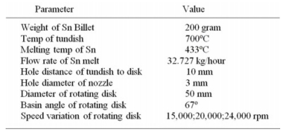
In the trial stage of making Sn powder, it is necessary to determine the testing parameters so that the test results obtained have the same parameter settings to make it easier in analyzing the resulting Sn powder. The test parameters are shown in Table 2.
The trial process for making Sn powder was carried out by heating 200 grams of tin in a tundish until the tundish temperature reached 700 oC, then the secondary heater was turned on 10 minutes before the motor spindle was set at a rotation speed variation of 15000 rpm, 20000 rpm, and 24000 rpm. The atomized powder from each rotation variation is then collected in a separate sample tube and labeled.
Maintaining the temperature in the atomization chamber so that it is at the melting temperature of the tin will determine the yield of the powder at each speed variation. Minimizing oxygen levels in the atomization chamber can be done by using a vacuum pump or by adding inner gas to the atomization chamber, which is done to obtain a spherical Sn powder form.
The sieving of powder results for each rotation variation, observations using an optical microscope of the powder produced in each rotation variation and XRD test of the powder in each rotation variation are the test steps carried out to determine the success rate of the centrifugal atomization machine. The powder from the atomization test results must be in accordance with the standard determined in ‘J-STD-005 Requirements for Soldering Pastes’ [18-20]. This is because the purpose of making this tin powder is for the purpose of making solder paste.
Design of centrifugal atomization machine using CAD
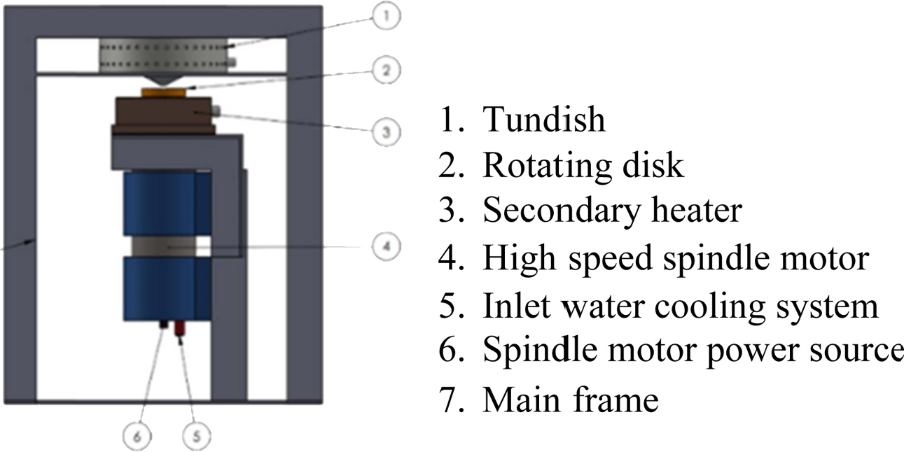
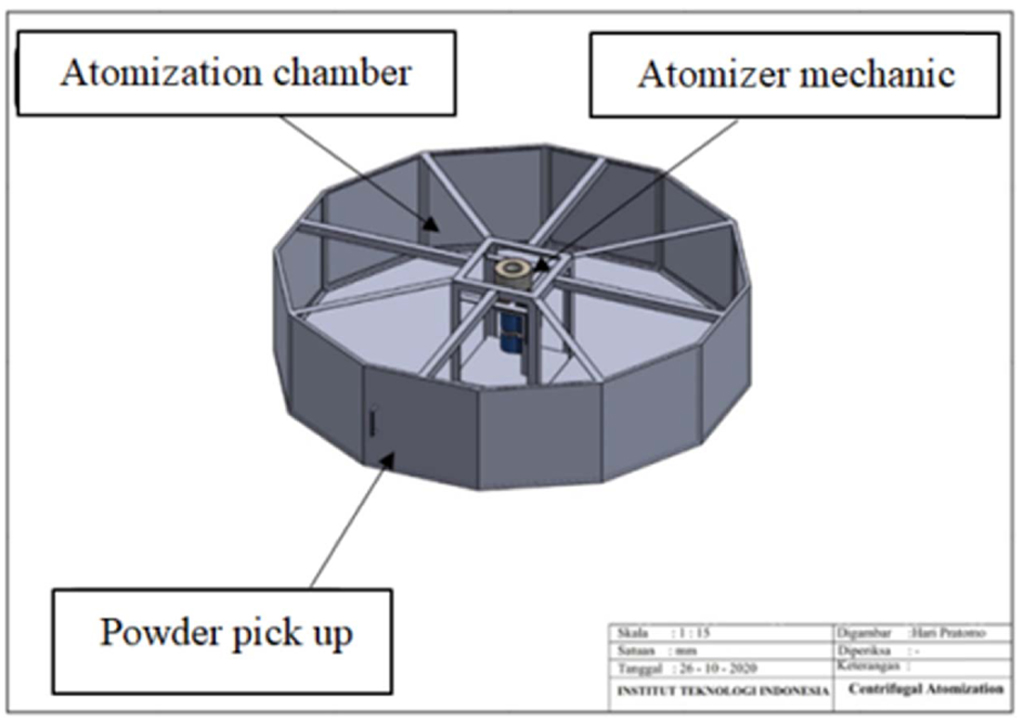
For the CAD design, the mechanical system design of the centrifugal atomization machine can be shown in Fig. 1. The atomizer component must be assembled with an atomization chamber based on the design using CAD. The placement of atomization component is shown in Fig. 2.
Calculation of motor pole mount and secondary heater bracket
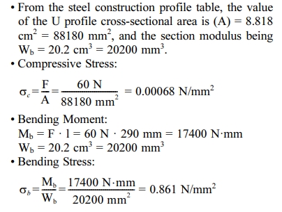
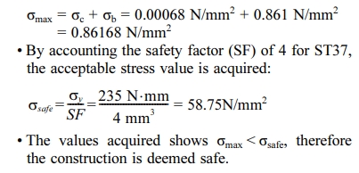
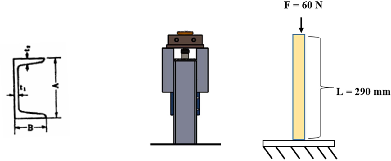
It is known that the U profile material (A x B x t1 x t2 = 75 x 40 x 5 x 7 mm) is made of ST37, with σy = 235 N/mm2 and the expansion coeffiecient of steel c = 0.000011 /oC. This U profile will be used to support the motor and the secondary heater with the total load of 6 kg and U profile length of 290 mm. Fig. 3. shows an illustration of the force acting on the motor mount and secondary heater bracket.
The calculations are shown below:
Secondary heater bracket calculations
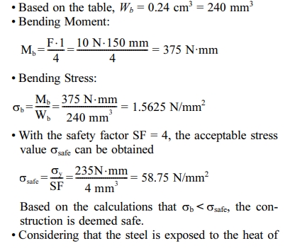
It is known that the material for the corner plate (20*20) is made of ST37, with σy = 235 N/mm2 and steel expansion coefficent of c = 0.000011/oC, with 2 of these corner plates used to support the secondary heater with a load of 1 kg, and the length of these corner plates being 150 mm. Fig. 4. shows the application of forces on the corner plates.
The calculations are shown below:

Tundish bracket calculations:
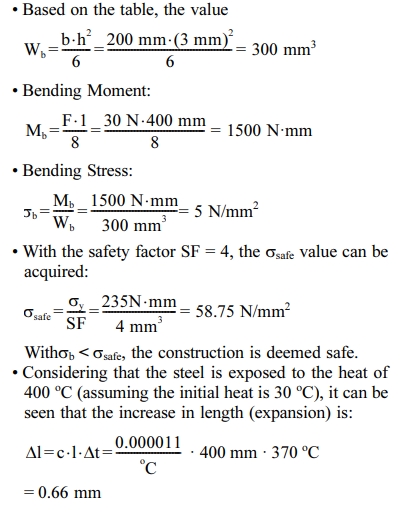
It is known that tundish bracket is made of ST37 with certain dimensions (3 x 20 x 400 mm), with yield stress value of σy = 235 N/mm2 and steel expansion coefficient of c = 0.000011 /oC. There are 2 plates used to suppot the tundish with a load of 3 kg.
The calculations are shown below:
Calculation of the fastener bolts and nuts for the secondary heater bracket
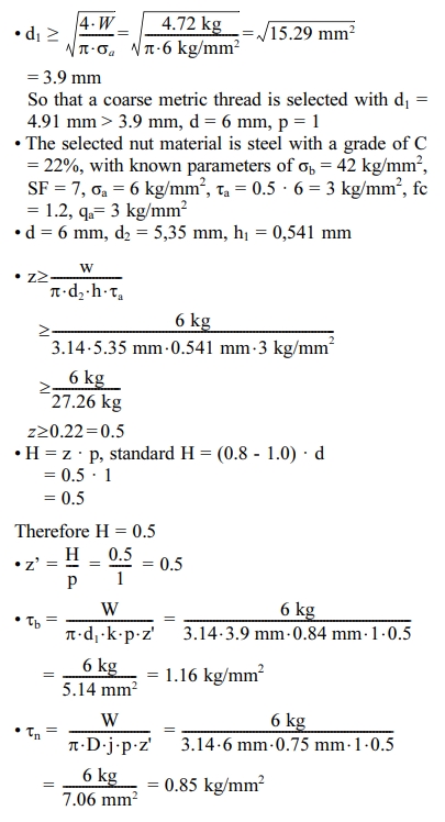
In the design of this bolt, the material used is steel with a grade of C = 22% and it is known that σb = 42 kg/mm2, SF = 7, σa = 6 kg/mm2, τa = 0.5 . 6 kg/mm2 = 3 kg/mm2, fc = 1.2 and the total weight sustained by the bolt Mtot = 60 kg, with W = 1.2 · 60 kg = 72 kg, therefore it can be calculated:
Atomized Sn powder sifting
The stage after collecting the powder into a large sample bottle is the sieving process, which aims to identify and classify powders based on their size from the atomization results.
Table 3 shows the percentage of success rate of powders produced from each experiment of making Sn powder using the centrifugal atomization method with variations in rotation, from this table it can be seen the efficiency of the powder manufacturing process from each rotation variation.
From Table 3 it can be seen that the higher the rotation of the rotating disk, the higher the percentage of powder obtained from atomization will be. This is because the higher the rotation of the rotating disk, the faster the friction of the molten tin material on the rotating disk becomes, resulting in less accumulation of molten tin material on the rotating disk. This will reduce the amount of tin in the form of granules that bounce off and stick to the walls of the atomization chamber. This is proportional to the basic principle of centrifugal force, which is that the higher the angular velocity value, the greater the centrifugal force produced. The greater the value of the resulting centrifugal force, the shorter the friction time of the molten tin on the surface of the rotating disk.
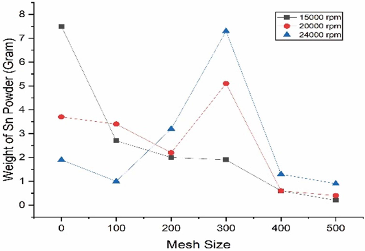
Sn powder from centrifugal atomization test results were grouped based on the rotation variation. Tests using sieving are carried out to determine the size distribution of the powder that can be produced based on variations in the rotation of the rotating disk. This sieving process is carried out in stages using sieve sizes of 100 meshes, 200 meshes, 300 meshes, 400 meshes, and 500 meshes. The results of each sieve size variation are shown in Fig. 5. From Fig. 5, it can be seen that the rotation of the rotating disk is very decisive on the size distribution of the resulting Sn powder, where the higher the rotation of the rotating disk, the higher the yield of small powder that will be obtained. This is due to the higher rotation of the rotating disk, the friction time between the molten tin material against the rotating disk will be shorter, with less friction time, the temperature of the tin towards the edge of the rotating disk is still at the melting temperature and still allows the formation of small tin powder grains to bounce.
With the lower rotation of the rotating disk, the friction time between the molten tin material and the rotating disk will be longer, which causes the melting temperature of tin to decrease slightly which results in the accumulation of molten tin material (skull) on the rotating disk. Another thing that is affected by the smaller rotation of the rotating disk is the distribution of the resulting powder, the largest powder size will be found in the coarse mesh size, while the smaller powder size will be less [21].
Based on the basic calculation of the centrifugal force, the rotation of the rotating disk will be inversely proportional to the size of the resulting powder, where the higher the rotation of the rotating disk will produce more small powders.
In the centrifugal atomization method used in this experiment, the dominant amount of powder was achieved at a sieve size of 300 meshes and the saturation point of powder size at a size of 300 meshes, which means that even if the rotation of the rotating disk is increased again, the highest amount of powder will be obtained at 300 meshes.
Testing using scanning electron microscope
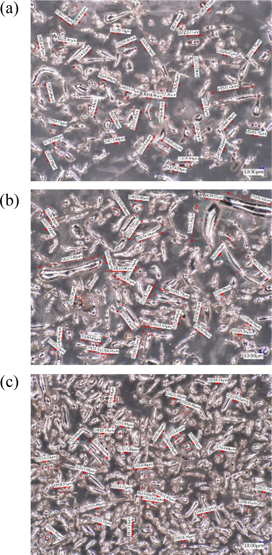
Tests using an optical microscope were used to determine the shape and size of the Sn powder obtained from the results of the centrifugal atomization test. This test uses a VHX-5000 digital microscope, from the observations of the powder from the centrifugal atomization test results can be shown in Fig. 6. Fig. 6 is a display of observations using an optical microscope for Sn powder. At 500 meshes, the resulting powder is dominated by ligamental and spherical shapes. In the spherical form, the size is between 15-25 microns. From the results of microscope observations at a magnification of 500 times with 500 meshes, the shape that is not homogeneous is caused by the less ideal rotation of the rotating disk. For the results obtained at 500 meshes, the uniformity of the shape of the resulting Sn powder is visible. At 1500 rpm there is a sample of impurities, this could be due to impurities from outside the environment during the atomization process.
For Sn powder produced at 20000 rounds with a mesh of 500 and a microscope lens magnification of 500 times, the powder form is dominated by fibrous, tear drop shapes. The spherical shape is obtained with a higher amount than centrifugal atomization with 15000 cycles. The size of the resulting spherical powder is 14-21 microns.
For Sn powder produced at 24000 rounds with 500 meshes and 500 times microscope lens magnification, the powder form is dominated by tear drops and sphericals. Spherical shapes are found in greater numbers than the lower rotating disk rotations. Spherical shapes are found in sizes 11-16 microns.
From observations using optical microscope at each rotation variation, it can be seen that the powder that occurs from the manufacture of Sn powder with the centrifugal atomization method is dominated by fibrous form, while for the comparison of spherical powders there are not as many compared.
From these data, Sn powder can be used as a basic material for making a low grade solder paste. To increase the grade, it is necessary to make homogeneous powders with a spherical shape. To make it into a spherical shape is to minimize the oxygen content in the atomization chamber [22].
Testing using XRD
This XRD test uses the Rigaku SmartLab, with the x-ray source being Cooper-Cu (40 kV, 30 mA), wavelength 1.541862 A, using the default 2Ɵ setting (10o - 90o), scan speed 5o/minute and step width 0.01o. This test was conducted to determine the crystal structure that occurs in the process of making Sn powder with the atomization method at each rotation variation. The parameters set in this XRD test are done by default from Rigaku, the variation is the difference in rotation of the rotating disk used to produce the powder. In theory, this centrifugal atomization method has low level of contamination, so it is very likely that the resulting powder is Sn powder without being con- taminated with other substances.
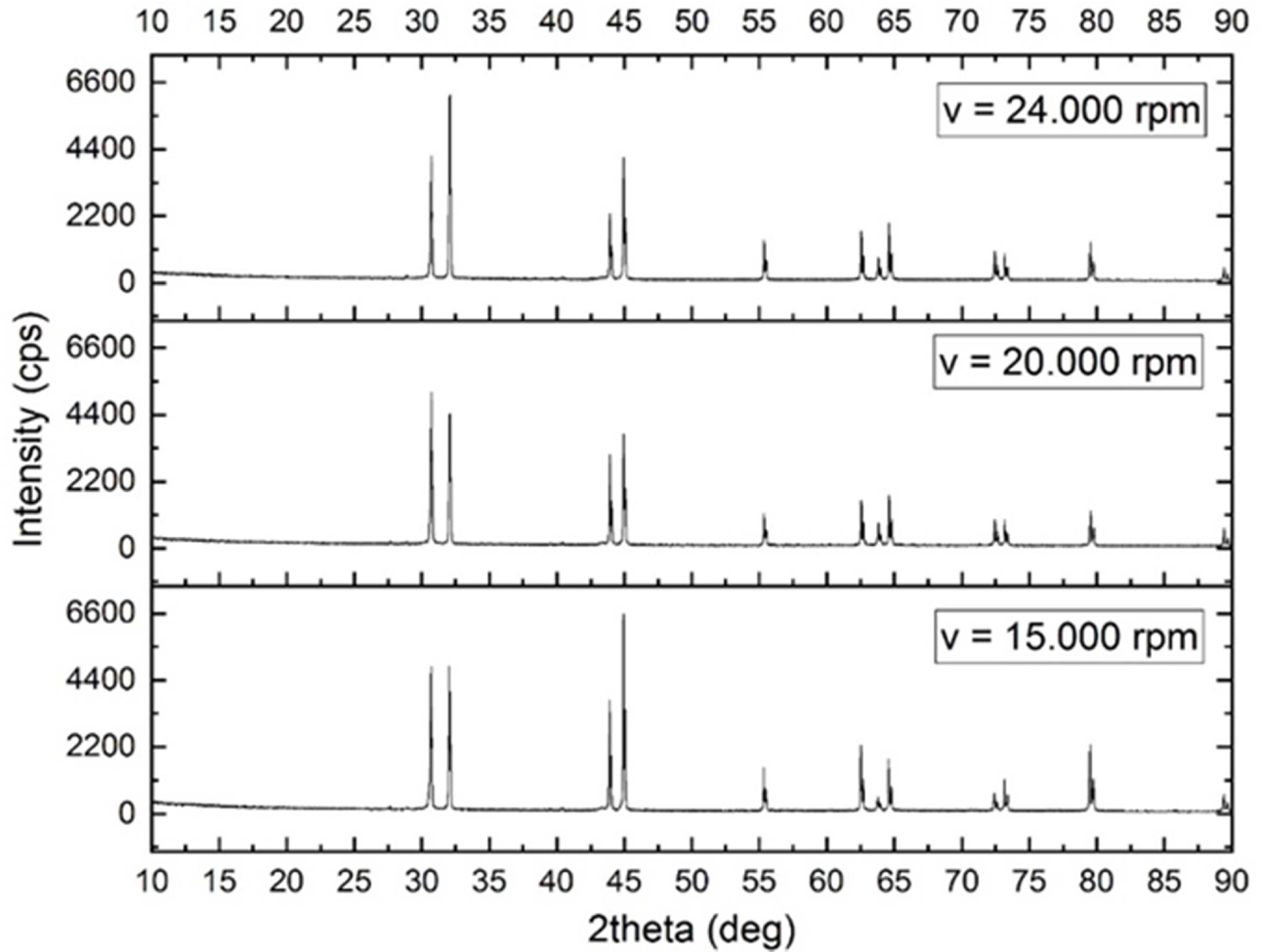
XRD testing was carried out using 3 variations of atomized powder, where the powder tested was the result of sifting at a sieve size of 300 meshes at 15000 rpm, 20000 rpm, and 24000 rpm rotation. The test of 3 variations of this rotation aims to determine whether there are any contamination of other substances and determine the effect of rotation on the powder phase of the powder produced in the centrifugal atomization process. For powder XRD results at 15000 rpm, 20000 rpm, and 24000 rpm, the data processing is carried out using Matchi software and the smoothing stage is carried out on the graph using Origin software, the results can be shown in Fig. 7.
It can be stated that the three diffraction patterns of each powder have the same pattern as the Sn diffraction pattern which means that the powder formed is tin powder, and based on the Macth software has a high compatibility level of A (acceptable), with the difference is in the intensity value.
Fig. 7 states that the tin powder produced from this centrifugal atomization method is very minimally contaminated with other substances, this is because in the trial process for making tin powder there is no addition of other substances that can contaminate the resulting tin powder.
The shape of the atomized tin peak has different intensities, this is due to the difference in the speed of the rotating disk, which greatly affects the shape and size of the tin powder produced during atomization. Where the higher the intensity value indicated by the diffractogram, the difference in the shape of the tin powder constituent crystals. The difference in the shape of the constituent crystals can be caused by differences in the shape of the tin produced during the atomization process.
Based on the histogram, in general the phase formed from the atomization results is tin, because the measured peak is identical to the peak database of tin. Based on the size of the resulting powder and analysis using XRD, it can be stated that the Sn powder formed is in accordance with the JCDC standard for type 2 powder.
|
Fig. 1 Atomizer system design |
|
Fig. 2 Atomization component placement. |
|
Fig. 3 Pole mount for the motor and secondary heater bracket. |

|
Fig. 4 Application of forces on the corner plates. |
|
Fig. 5 The sifted powder in each rotation variation. |
|
Fig. 6 Observation of micro structure 500x Sn powder 500 meshes (a. 15000 rpm, b. 20000 rpm, and c. 24000 rpm). |
|
Fig. 7 Sn powder diffractogram on each variation. |
From the design activities of the centrifugal atomiza- tion machine and trials of making Sn powder with variations in rotation, some things can be concluded:
1. From the calculation of the strength of the material, each component is declared safe because the stress that occurs is lower than the allowable stress of the existing material. It is concluded that the force acting on the motor mount and secondary heater bracket is a compressive force where smax = 0.86168 N/mm2, The force acting on the secondary heater bracket is a bending moment where the bending stress is 1,5625 N/mm2, and the force acting on the tundish bracket is a bending moment where the bending stress is 5N/mm2.
2. From the calculation of the strength of the secondary heater bracket bolts, the bolts with the material used being steel with a C grade of 22% and it is known that sb = 42 kg/mm2, SF = 7, sa = 6 kg/mm2, τa = 3 kg/mm2, with diameters of 6 mm.
3. From the calculation of the strength of the bolts and nuts fastening the secondary heater bracket, the selected nut material being steel with a grade of C = 22%, it is known that sb = 42 kg/mm2, SF = 7, sa = 6 kg/mm2, τa = 3 kg/mm2, fc = 1.2, qa= 3 kg/mm2, with diameters of 6 mm.
4. The higher the rotating disk rotation, the lower the amount of tin agglomeration on the rotating disk.
5. This centrifugal atomization method achieves a dominant amount of powder and a saturation point of powder size at the mesh size of 300, which means that even if the rotation of the rotating disk is increased again, the highest amount of powder that can be obtained will be at mesh 300.
6. According to the standards set in ‘J-STD-005 Re- quirements for Soldering Pastes’ [13], the resulting Sn powder can be classified as a Type 2 powder.
7. The manufacture of Sn powder using the centrifugal atomization method minimizes the possibility of contamination from other substances, because the process only uses heating and splitting of metallic liquids using a rotating disk and does not use additional materials that can cause contamination of substances.
The authors are grateful to the Ministry of education, culture, research and technology and The Republic of Indonesia for the Research Grant based on 3492/LL3/KR/2021, Multy Years Fundamental Research 2021.
- 1. C.D. Zou, Y. Gao, B. Yang, and Q. Zhai, Trans. Nonferrous Met. Soc. Chin. 20[2] (2010) 248-253.
-

- 2. L. Huiping, P. Sakiropulos, and T. Jhonson, K. Eng. Mater. 189-191[1] (2001) 245-251.
- 3. İ. Topcu, J. Ceram. Proc. Res. 22[2] (2021) 143-148
-

- 4. M.S. Kim, J. Ceram. Proc. Res. 21[1] (2020) 119-122
-

- 5. A. Basyir, D. Aryanto, and A.S. Wismogroho, in Proceedings of the Seminar Nasional Fisika (E-Journal) SNF2020, June 2020, edited by M. Delina (Universitas Negeri Jakarta, 2020) p.21-28.
- 6. P. Sungkhaphaitoon, T. Plookphol, and S. Wisutmethangoon, Int. J. Appl. Phys. Math. 2[1] (2012) 77-82.
- 7. F.S. Biancaniello, R.D. Jiggetts, and R.E. Ricker, in Pro- ceedings of the TMS Annual Meeting and Symposium, March 2000, edited by E.K. Ohriner (TMS, 2000) p. 263-274.
- 8. Y. Miyasaka, Jpn. Soc. Mech. Eng. 17[1] (1974) 1461-1468.
-

- 9. F. Hidayanti, T. Yulianto, and A.S. Wismogroho, J. Sains. Teknol. 8[2] (2016) 113-127.
-

- 10. W. Dong, Y. Meng, F. Xu, Y. Han, Y. Wang, X. Wang, Y. Zhao, Powd. Metal. Met. Ceram. 59[5-6] (2020) 239-248.
-

- 11. L.P. Zhang and Y.Y. Zhao, Elsevier 318[1] 2017 62-67.
-

- 12. Y.Y. Zhao, Elsevier 27[1] (2005) 745-750
- 13. O.A. Shemyakina, Z.I. Sheikhalieva, and S.M. Sheikhaliev, Rus. J. Non-Ferrous Met. 51[3] (2010) 250-254.
-

- 14. J. Setiawan and Sungkono, Powd. Metal. Met. Ceram. 59[1] (2017) 5-6.
- 15. P. Gopi Krishnana, B. Suresh Babub, and K. Sivac, J. Ceram. Proc. Res. 21[2] (2020) 157-163
-

- 16. J.U. Hura, J.H. Kimb, G.S. Ana, S.C. Choia, J. Ceram. Proc. Res. 21[2] (2020) 213-216
-

- 17. A.H. Oh, H.S.Lee, B.G.Kim, S.C. Choi, Y.G. Jung, G.S. An, J. Ceram. Proc. Res. 21[4] (2020) 400-406
-

- 18. Solder Paste Task Group, in J-STD-005 Requirements for Soldering Pastes (Electronic Industries Alliance (EIA) and IPC (1995) 1.
- 19. V. Nevruzoglu, M. Manir, G. Ozturk, J. Ceram. Proc. Res. 21[2] (2020) 256-262
-

- 20. Y. Liu, J. Song, L. Chen, H. Luo, G. Lin, P. Chen, C. Wei, J. Liu, J. Ceram. Proc. Res. 21[4] (2020) 488-494
-

- 21. D. Suastiyanti, Y.N. Maulida, J. Ceram. Proc. Res. 22[1] (2021) 61-65
-

- 22. M. Sheikhaliev, Z.I. Sheikhalieva, and J.J. Dunkley, Metal Powder Report 63[2] (2008) 28-30.
-

 This Article
-
2021; 22(6): 705-713
Published on Dec 31, 2021
- 10.36410/jcpr.2021.22.6.705
- Received on Aug 4, 2021
- Revised on Oct 8, 2021
- Accepted on Oct 9, 2021
 Services
- Abstract
introduction
experimental
results and discussion
conclusions
- Acknowledgements
- References
- Full Text PDF
Shared
 Correspondence to
- Dwita Suastiyanti
-
Department of Mechanical Engineering, Institut Teknologi Indonesia, Puspiptek Raya Street, Tangerang Selatan, 15314 Indonesia
Tel : +62-85697163727 Fax: +62-7561091 - E-mail: dwita_suastiyanti@iti.ac.id



 Copyright 2019 International Orgranization for Ceramic Processing. All rights reserved.