


- Optimization and analysis of microstructural friction stir welded AA5083 grade aluminium alloy
P. Muthurasua,* and M. Kathiresanb
aLecturer, Department of Mechanical Engineering, Government Polytechnic College, Tuticorin- 628 008.
bProfessor, Department of Mechanical Engineering, E.G.S. Pillay Engineering College, Nagapattinam - 611002This article is an open access article distributed under the terms of the Creative Commons Attribution Non-Commercial License (http://creativecommons.org/licenses/by-nc/4.0) which permits unrestricted non-commercial use, distribution, and reproduction in any medium, provided the original work is properly cited.
The present work is the novel approach to optimize the friction stir welding process of aluminium AA5083 alloy by utilizing Taguchi L9 orthogonal array technique. The present work also investigated the mechanical and metallurgical characteristics of the weld joint. The present work involved three input friction stir welding parameters that were varied in the investigation under the Taguchi L9 orthogonal array experimental methodology. The experimental methodology was utilized to predict the optimal input parameters to obtain peak tensile strength and hardness values of the welded joint and the signal to noise (S/N) ratio and results of the Analysis of variance (ANOVA) were also investigated. The optimal tool rotational speed, welding speed and tool tilt angle were 560 rpm, 60 mm/minute and 1 degree respectively for the peak joint tensile strength and 560 rpm, 80 mm/minute and 1 degree for peak joint hardness. The results from ANOVA indicated that the highest influencing input factor of the weld joint was tool tilt angle followed by the welding speed and tool rotational speed. Metallurgical analysis of the joint revealed fine grain structure within the stir zone which directly resulted in the enhancement of the weld joint properties
Keywords: FSW, optimization, Tensile strength, Hardness, Chemical analysis
The AA5083 aluminium alloy possesses magnesium as the primary alloying element and has superior wear and corrosion resistance, high strength to weight ratio, good specific strength, fracture toughness and relatively low-cost of production. These properties are the most beneficial in marine and automobile applications. Typical aluminium alloy joints are joined by conventional fusion techniques which affect the dissolution in the weld joint and promotion of strengthening precipitates in the thermal cycle [1, 2]. Obtaining a sound weld joint is difficult due to the occurrences of solidification cracks, slag inclusions and porosities due to coarse grains during conventional welding techniques [3]. Friction stir welding (FSW) is a solid-state welding process developed in the recent years that has earned extensive attention owing to its numerous benefits [4], and when compared with traditional fusion welding methods, this method doesn’t employ recast or melting of materials during welding [5]. The FSW process parameters primarily influence the output mechanical and metallurgical characteristics of the weld joint [6]. Studies have con- centrated on investigating the effects of these parameters such as welding speed, tool rotational speed, axial load, tool geometry, tool angle etc., to determine their respec- tive influence on the output properties of the welded specimen [7, 8]. The Taguchi method is a tool for determining the major influencing factor from a series of predetermined amount of experimental trials [9]. Further studies have investigated effects of input para- meters and methods to obtain enhanced results by utilizing Taguchi orthogonal array technique [10]. Similarly, Kolraj et al. [11] investigated optimization of FSW parameters for dissimilar aluminium alloy joint by Taguchi method. Shojaeefard et al. [12] obtained enhanced FSW joint by experimenting with tool pin profile, tool rotational speed, welding speed, tool pin profile and tool penetration depth by Taguchi method. Ravichandran et al. [13] had studied parameters of FSW process such as tool shoulder diameter, tool rotational speed, welding speed for enhancing ultimate tensile strength of the joint. Kimura et al. [14] explored optimization of FSW parameters for similar AA5052 joint. The optimized weld joint, in the vicinity of the softened area, possessed a joint efficiency of 93% and the tensile test specimens fractured in the base metal section. Geng et al. [15] had also explored friction stir joint of aerospace grade AA2024 and the obtained Taguchi method optimized friction stir joint reached 92% joint efficiency and fine recrystallized grains were observed in the friction stir zone. With the aid of high temperature tool friction, the specimen materials experi- ence high plastic deformation at elevated temperatures, that result in finer grains and balanced microstructure [16, 17]. Enhanced joint microstructure lead to improved mechanical and metallurgical characteristics of the welded joint. Pandiyarajan et al. [23] had characterized the friction stir welded joint of hybrid AA6061 metal matrix composite (MMC) with ZrO2 and C reinforce- ments and found that heat input conditions were influential in determining the peak tensile strength and microhardness levels of the welded specimen. Gopi Krishnan et al. [24] in their study, explored optimiza- tion of FSW process parameters in welding of SiC-Al2O3 composites by utilizing genetic algorithm technique and Taguchi L27 orthogonal array for experimental methodology and found that the Tool rotational speed was the most influential parameter followed by the welding speed and axial load. Srinivasan et al. [25] investigated the optimization of FSW parameters for AA6063 hybrid MMC by genetic algorithm and regression analysis. They also found that stir casting played an important role in determining the inherent performance characteristics of the specimen. Suresh Babu et al. [26] explored the fabrication and character- ization of performance properties of FS welded AA6062 compete with graphite, boron carbide and silicon carbide reinforcements and found that the 20-weight percentage of the reinforcements provided enhanced mechanical and metallurgical properties for the welded specimen. Sonomura et al. [27] has studied friction stir spot welding of dissimilar Silicon carbide and AZX612 aluminium alloy and found segregation of magnesium compounds along the weld interface indicative of parent metals affected by friction stir spot welding. The aluminium compounds formed as a result had greatly influenced the welded interface. Sabbaghian et al. [28] had investigated friction stir processing on a copper-titanium carbide composite, and explored the performance characteristics. They authors found formation of homo- genous material particles distribution on the material surface. The friction stir process had resulted in grain refinement that has led to improved microhardness and wear resistance of the of the specimens.
In the present work, Taguchi L9 orthogonal array was used to obtain optimized input FSW process parameters for AA5083 joint for enhanced output joint mechanical and metallurgical properties. Subsequently, the optimized joint was tested for joint tensile strength, microhardness and microstructure characterization. The specimen was analyzed for microstructural enhance- ments in critical welding affected zones such as heat affected zone, thermo-mechanically affected zone, weld nugget zone by optical microscopy, scanning electron microscopy and energy dispersive spectroscopy.
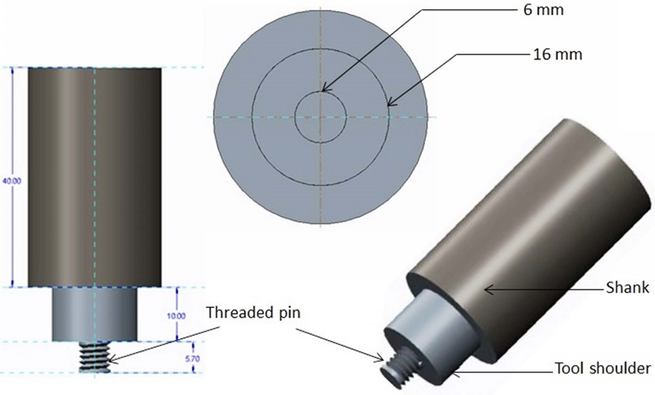
The present work involved friction stir welding of aluminium AA5083 alloy plates with 6mm thickness. The composition of the specimen plates and their properties are stated in Tables 1 and 2 respectively. The AA5083 alloy plates with the dimensions of 120 mm x 100 mm x 6mm friction stir welded by a modified vertical milling machine. The butt-joints formed by the friction stir welded as per the L9 orthogonal array experimental methodology. The input parameters that were varied over the course of the experiment were friction stir tool rotational speed (rpm), stir tool welded speed (mm/minute) and tool tilt angle (degree). The friction stir welding tool was made from H13 grade steel with 5.7 mm pin length, 6 mm pin diameter, 16 mm tool diameter and a 40 mm shank (Fig. 1). The position of the tool pin was placed in the midst of the joint region during welding process and the tool was rotated in the clockwise direction.
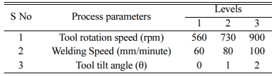
The Taguchi method technique was utilized to optimize the welding process for FSW AA5083 grade aluminium joint. A suitable orthogonal array (L9) was be chosen liable on the total degree of freedom (DOF), which can be calculated by summation of specific degree of freedom for each FSW parameters. The levels of the individual FSW parameters were selected by means of preceding literatures (Table 3). Subsequently, the array with 8 different degrees of freedom was designated to estimate the properties of the welding parameters based on tensile and micro hardness of AA5083 alloy.
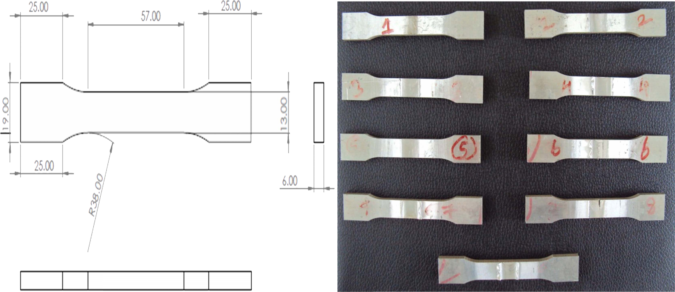
The tensile test samples were wire-cut electrical discharge machined with adherence to ASTM E8 M-04 standard to obtain dimensionally smooth specimens. The specimens were tested by universal testing machine to determine the tensile performance of the specimens at standard testing conditions. The tensile test samples and their dimensions are illustrated in Fig. 2. The microhardness survey was conducted on the various weld zones by Vickers hardness testing machine. The testing samples were prepared as per ASTM E384 standard and the testing load was applied in steps of 0.5 kgf for 10 s time limits. The fastened welded samples were subsequently ground and polished by abrasive paper. The specimens were treated with Keller`s reagent for 25 s and optical microscope (Nikon DIC) was used to analyze the microstructural variations and possible occurrences of flaws by Clemex image analysis. The welded samples were then subjected to SEM and EDAX analysis.
|
Fig. 1 Geometry of the FSW tool. |
|
Fig. 2 Tensile test samples prepared according to ASTM E8 M-04. |


S/N Ratio
The Signal to noise ratio determines the quality of the attributes of the process. The designated target function causes the enhancements in mechanical properties (tensile strength and microhardness) of the welded joint. It is thus observed that higher levels of S/N ratio were to be analyzed. The S/N ratio was calculated by Therefore, the larger and better S/N ratio is to be analyzed.
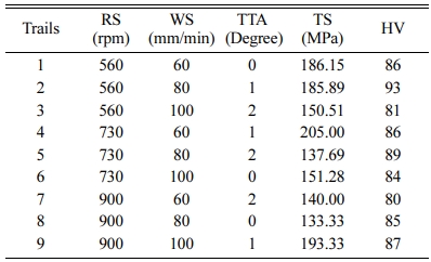
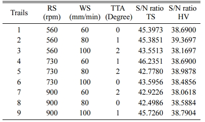
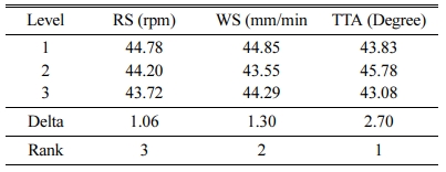
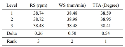
The tensile strength and microhardness of the 9 sample specimen FSW joints after the mechanical testing were listed in Table 4. The mean value and S/N ratio for both tensile strength and microhardness were presented in Table 5. As can be observed from the Tables 4 and 5, the optimal weld input parameter values to obtain peak values for both tensile strength and micro- hardness at varying input parameter levels. Tables 6 and 7 presented the response values for the S/N ratios for both tensile strength and microhardness respectively. The response values also varying among them for each combination of the three input parameters (tool rotational speed, welding specimen and tool tilt angle) as part of the experimental methodology. The higher S/N ratio typically result in enhanced joint characteristics [18, 19]. The R1S1T2 was observed to be the optimal input parameter setting for obtaining peak tensile strength as observed form Table 6. Thus, based on all the experi- mental inference the R1S2T2 was observed to be the optimal input parameter setting for microhardness in Table 7.
ANOVA
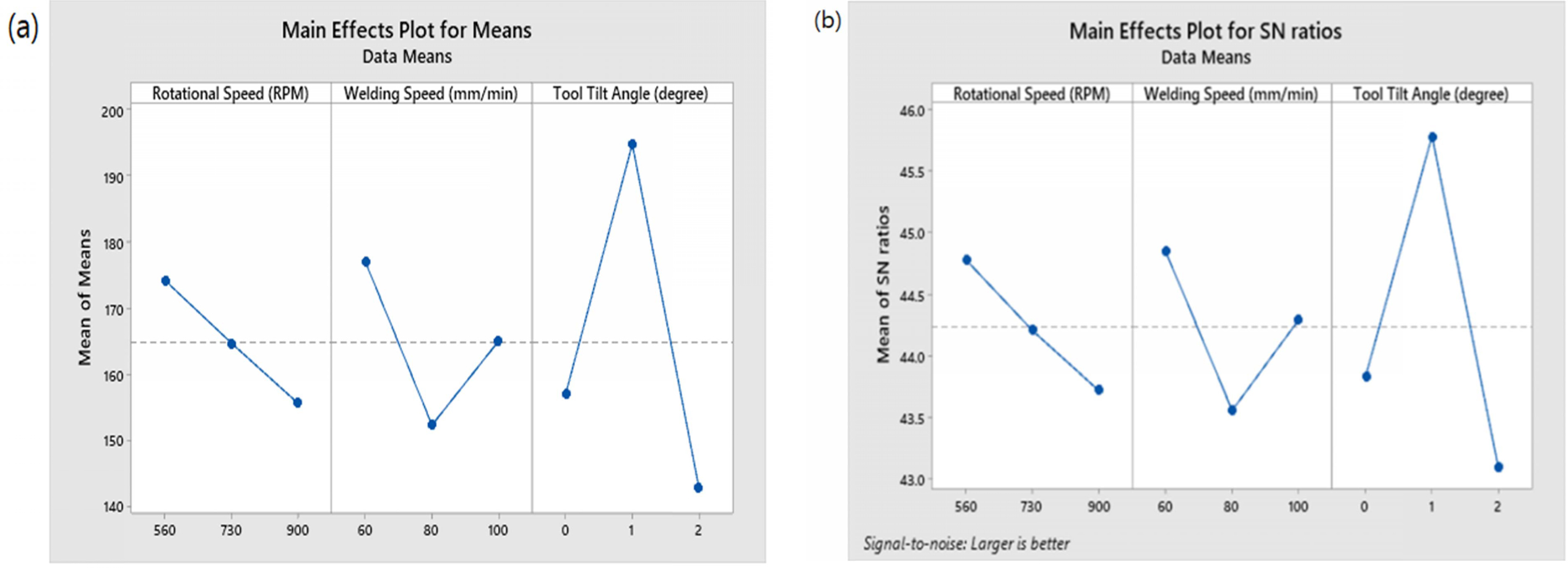
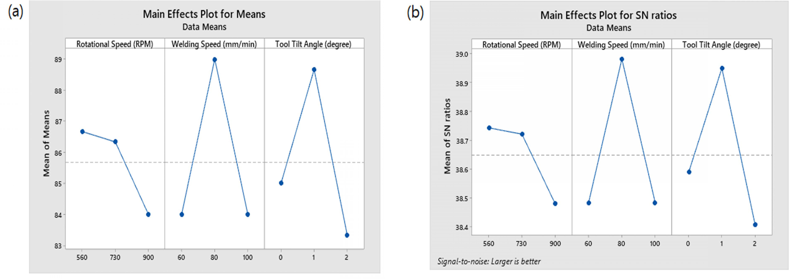
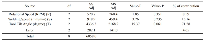
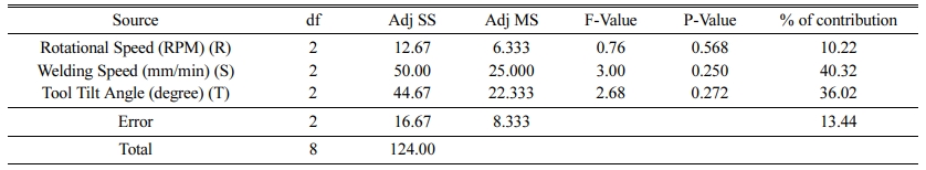
Analysis of Variance (ANOVA) is a collecti7on stati- stical models used to assert the significance of the experimental results. In the present work, it was used to determine the significance of the influencing input FSW process parameters and determine the highest influencing parameter. The ANOVA for the mean tensile strength and microhardness levels are listed in Tables 8 and 9 respectively. The main effect plots for the mean value and S/N ratio for the input parameters were illustrated in Figs. 3 and 4. The input parameter with the peak F-value in Tables 8 and 9 was observed to be tool tilt angle for both tensile strength and microhardness of the FSW joint.
By means of various experimentations, the optimal input parameters were identified for the output responses: tensile strength and microhardness which were R1S1T2 and R1S2T2 respectively. The peak value of tensile strength was observed at the optimal levels of these parameters. The influencing input parameters and their optimal levels for obtaining peak tensile strength were determined to be tool rotational speed (level 1) = 560rpm, welding speed (level 1) = 60 mm/minute and tool tilt angle (level 2) = 1o as observed from Table 6. Similarly for peak microhardness, the optimal input FSW parameters were determined to be, tool rotational speed (level 1) = 560rpm, welding speed (level 1) = 80 mm/minute and tool tilt angle (level 2) = 1o as observed from Table 7. The optimal parameters were determined by usig a friction stir welding tool with a cylindrical threaded pin profile. The peak tensile strength was observed to 209 MPa and Vickers microhardness to be 98 HV with the optimal input parameters for the FSW of AA5083 specimen.
Microstructure of friction stir welded AA5083 optimum joint
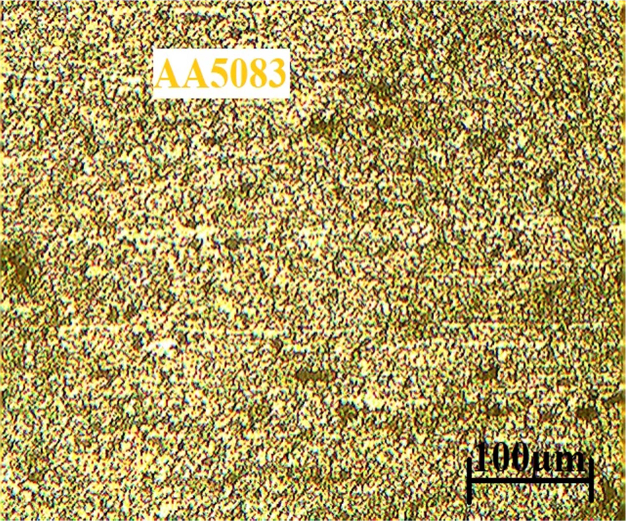
The microstructures of the base metal aluminium matrix and various zones of the friction stir welded specimen were explored by optical and scanning electron microscopy. The samples were investigated in the traverse cross section of the finest weld region which was previously polished by Keller`s reagent for observational purposes. The microstructure of the base metal AA5083 is illustrated in Fig. 5, where the parallel grain structure of the cold worked AA5083 can be observed. The presence of magnesium silicide (Mg2Si) eutectic constituents along the direction of the primary aluminium solid solution.
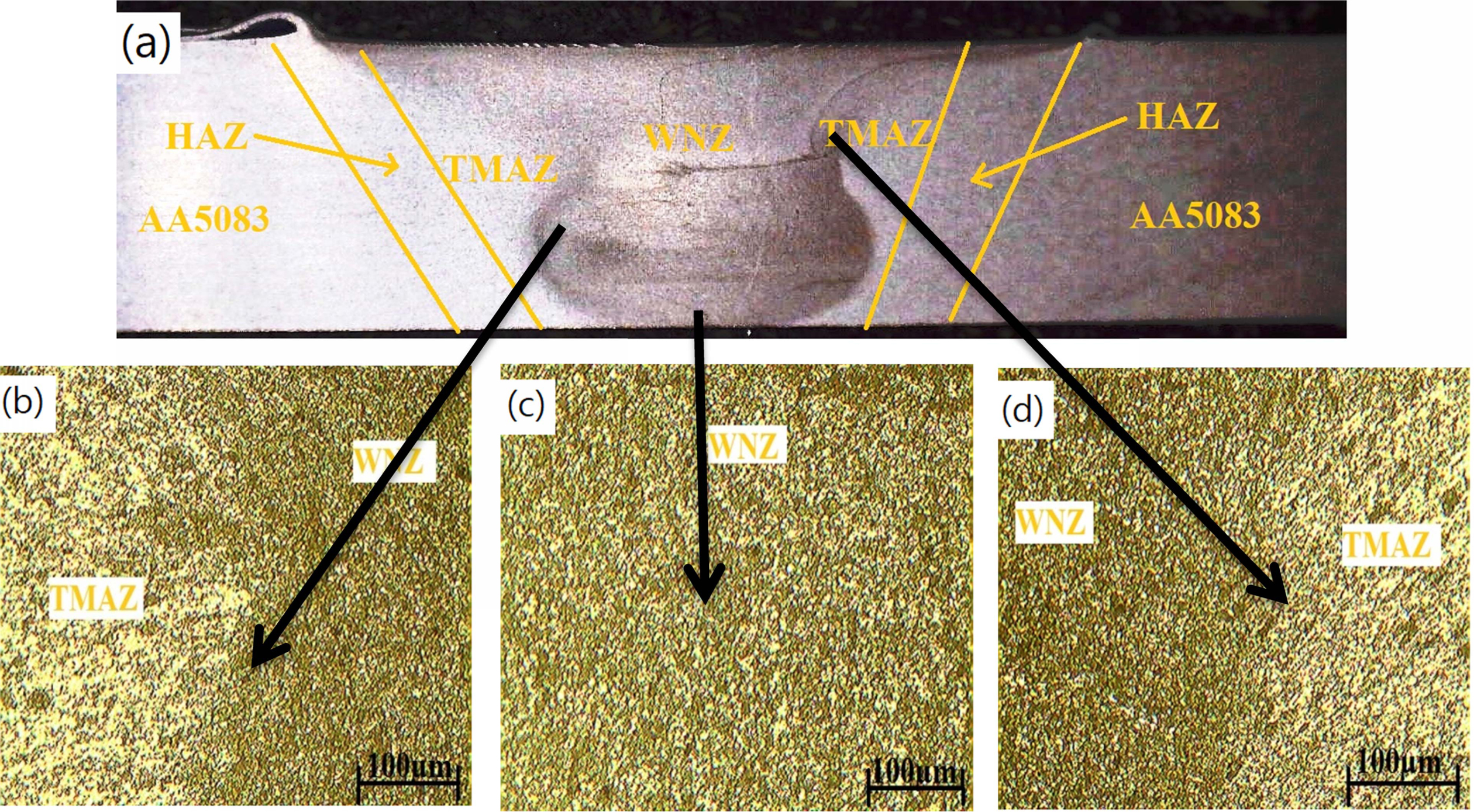
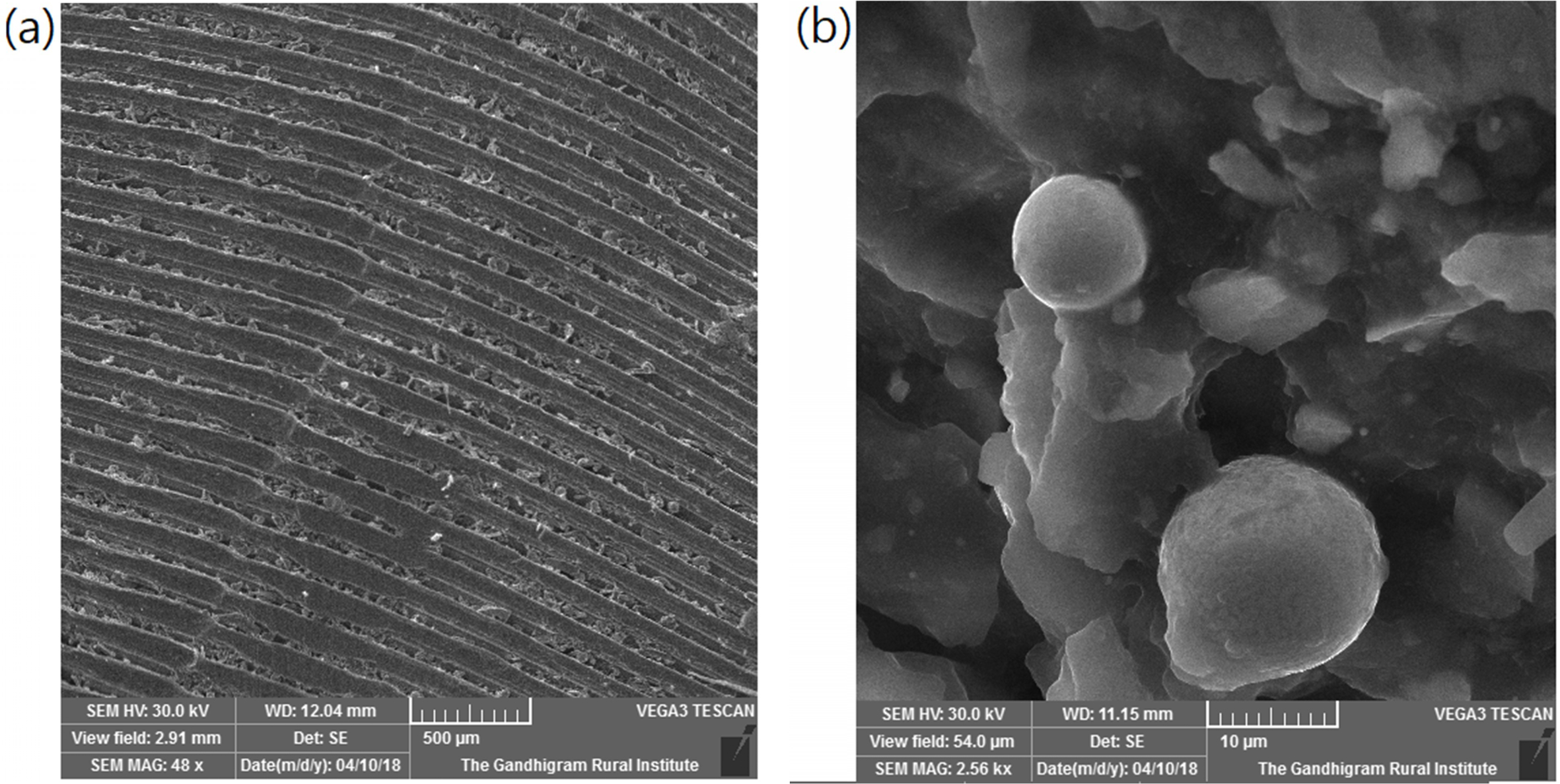
The macrostructure at Fig. 6(a) illustrates the various zones of the friction stir welded AA5083 specimen. The micrographs illustrated in Figs. 6(b), 6(c) and 6(d) illustrate the multifaceted circle pattern surrounding the weld nugget zone (WNZ). The interface between the thermo-mechanically affected zone (TMAZ) and WNZ can be observed to be markedly defined as illustrated in Figures 6(b) and 6(d). The growth of the WNZ until the top weld plate can be observed which was due to the effect of the friction stir tool shoulder. The tool shoulder had created a rousing effect during the welding process when it touched the specimen and stirred down the plate. It was observed that on the top area of the specimen plate. The TMAZ observed to be neighboring the WNZ in Figs. 6(b) and 6(d). It was apparent that the metal matrix had undergone dissolution of Mg2Si particles and the grains showed subsequent partial recrystallization. The micrograph illustrated the presence of fusion line in the weld interface between the AA5083 and the WNZ in the center. The TMAZ showed partial dissolution of some Mg2Si particles. The WNZ showed fine grained fragmented particles of Mg2Si in aluminium matrix shown in Fig. 7. The stir zone had slightly better and equated grains. This structure was formed due to recrystallization and inert grain growing [20].
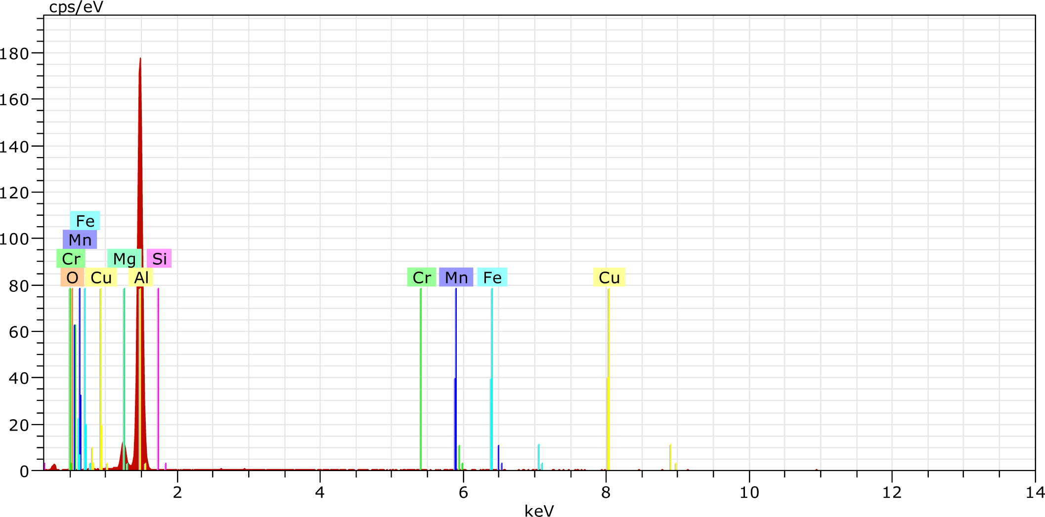
The chemical composition of friction stir welded WNZ shown in Fig. 8. The varieties of particles were characterized by energy dispersive spectroscopy. The AA5083 is rich in Mg and Fe or a multifaceted phase, rich in Mg, Si, and O2. These were observed in the optimized WNZ zone. The other variants were observed as well such as Si and O2 rich particles [21]. The minor particles were difficult to analyze, mainly they are rich in Mg and Si.
Microhardness Analysis
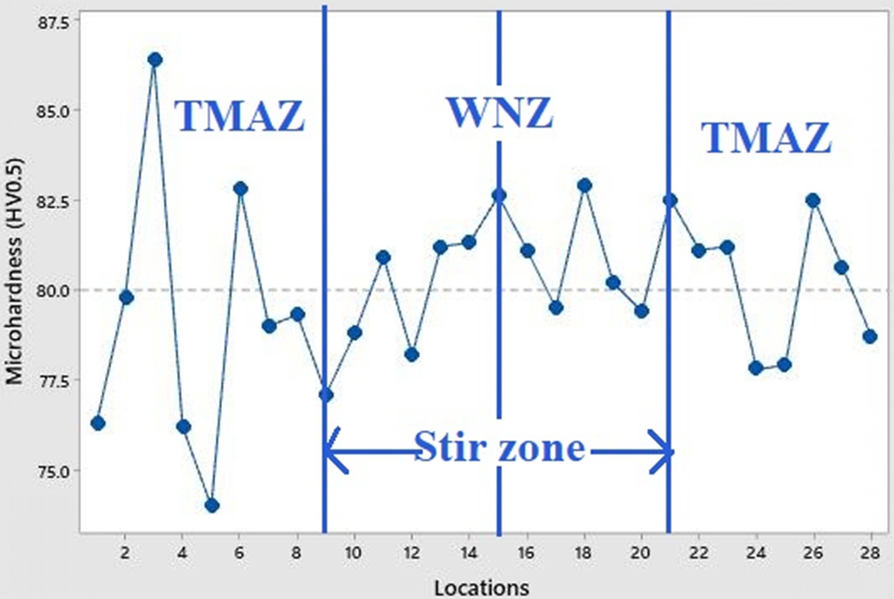
The optimized FSW AA5083 joint was surveyed in various zones to determine the Vickers microhardness levels. The results of the microhardness survey illustrated in Fig. 9 show the microhardness profile of the parallel joint friction stir welded at tool rotational speed = 560 rpm, welding speed = 80 mm/minute and tool tilt angle = 1o. The dotted vertical lines indicate the lowest microhardness values observed at TMAZ. The unaffected base metal matrix exhibited 93 HV0.5 which indicated that it was tougher and this trend declined when moving towards the weld region. The TMAZ possessed 74 HV0.5 which was the lowest microhardness value in comparison to the base metal and WNZ [22]. The microhardness level of 83 HV0.5 observed in TMAZ was the highest possible microhardness that it could exhibit.
|
Fig. 3 Main effects plot for tensile strength (a) Means (b) S/N ratio. |
|
Fig. 4 Main effects plot for microhardness (a) Means (b) S/N ratio. |
|
Fig. 5 Microstructure of the base metal AA508. |
|
Fig. 6 Friction stir welded AA5083 (a) cross sectional macrostructure view of weld joint (b) microstructure of weld interface (c) microstructure of weld nugget zone (d) microstructure of weld interface. |
|
Fig. 7 SEM micrograph of friction stir welded nugget zone. |
|
Fig. 8 Chemical composition of weld nugget zone. |
|
Fig. 9 Microhardness analysis of optimized friction stir weld joint. |
In the present work, the input friction stir welding process parameters of AA5083 aluminium alloy were optimized to obtained enhanced tensile strength and microhardness for the welded joint by Taguchi method using L9 orthogonal array experimental methodology.
• The optimal input parameters found were tool rotational speed = 560rpm, welding speed = 80 mm/minute and tool tilt angle = 1o.
• The tool tilt angle was found to be the most influencing input parameter among the input process parameters followed by welding speed. Tool tilt angle had a weld influencing significance of 71.58 %.
• The fractures observed during tensile testing of the specimens were located on the TMAZ adjacent to the stir zone. The improved grain sizes led to enhanced microhardness inadvertently causing higher crack strength in the joint.
• The microstructure of the WNZ consisted fine fragmented eutectic Mg2Si particles and the matrix had subsequently undergone recrystallization owing to rapid stirring action and high frictional heat generated during the FSW process coupled with internal buildup of stress. The metal matrix was observed to undergone dissolution of Mg2Si particles and the grains show partial re-crystallization in the TMAZ.
• The Microhardness survey was conducted succe- fully and higher hardness value was oberved in the WNZ; lower microhardness was observed in the TMAZ, compared to base metal of AA5083 and WNZ.
FSW: Friction Stir Welding
ANOVA: Analysis of variance
HAZ: Heat-Affected
TMAZ: Thermally Mechanically Affected Zone
WNZ: Weld Nugget Zone
SEM: Scanning Electron Microscope
OM: Optical Microscopy
EDS: Energy Dispersive X-ray Spectroscopy
UTS: Ultimate Tensile Strength
YS: Yield Strength
HV: Hardness Value
RS: Rotational Speed
WS: Welding Speed
TTA: Tool Tilt Angle
The authors are grateful for the support rendered by Govt. polytechnic college and E.G.S. Pillay Engineering College Nagapattinam. They sincerely thank their re- spective departments of Mechanical Engineering for lending their support.
There are no potential conflicts of interest and funding reported by the authors.
- 1. E. Taban and E. Kaluc, Met. Mater. 44 (2006) 24.
- 2. S. Ji, R. Huang, X. Meng, L. Zhang, and Y. Huang, J. Mater. Eng. Perform. 26 (2017) 2359 -2367.
-

- 3. A. Abdolahzadeh, H. Omidvar, M.A. Safarkhanian, and M. Bahrami, Int. J. Adv. Manuf. Technol. 75 (2014) 1189- 1196.
-
- 4. W.B. Lee, Y.M. Yeo, and S.B. Jung, Scripta. Mater. 49 (2003) 423-428.
-
- 5. Y. Li, L.E. Murr, and J.C. McClure, Mater. Sci. Eng. A 271 (1999) 213-223.
-
- 6. H.M. Rao, B. Ghaffari, W. Yuan, J.B. Jordon, and H. Badarinarayan, Mater. Sci. Eng. A 651 (2016) 27-36.
-
- 7. P. Cavaliere, Proced. CIRP 11 (2013) 139-144.
-
- 8. H. Khodaverdizadeh, A. Mahmoudi, A. Heidarzadeh and E. Nazari, Mater. Des. 35 (2012) 330-334.
-
- 9. N.D. Ghetiya, K.M. Patel, and A.J. Kavar, T. Indian I Metals 69 (2016) 917-923.
-
- 10. S. Kasman, Int. J. Adv. Manuf. Tech. 68 (2013) 795-804.
-
- 11. M. Koilraj, V. Sundareswaran, S. Vijayan, and S. Koteswara Rao, Mat. & Des. 42 (2012) 1-7.
-
- 12. M.H. Shojaeefard, M. Akbari, A. Khalkhali, P. Asadi, and A.H. Parivar, Mat. & Des. 64 (2014) 660-666.
-
- 13. M. Ravichandran, M. Thirunavukkarasu, S. Sathish, and V. Anandakrishnan, Mater. Test. 58 (2016) 206-210.
-
- 14. M. Kimura, M. Choji, M. Kusaakal, K. Seo, and A. Fuji, J. of Sci. Tech. of Weld. & Joi. 11[2] (2006) 209-215.
-
- 15. P.-h. Geng, G.-l. Qin, J. Zhou, and C.-a. Li, Trans. Nonfer. Met. Soc. China 29 (2019) 2483-2495.
-
- 16. B. Hari Babu and K. Madhivanan, Int. J. Adv. Res. Trends Eng. Tech. 2 (2015) 78-83.
- 17. P. Cavaliere, A. De Santis, F. Panella, and A. Squillace, Mater. Des. 30 (2009) 609-16.
-
- 18. S. Vijayan, R. Raju, K. Subbaiah, N. Sridhar, and S.R.K. Rao, Exp Tech. 34[5] (2010) 37-44.
-
- 19. S. Vijayan, R. Raju, and S.R.K. Rao, Mater. Manuf. Proc. 25[11] (2010) 1206-12.
-
- 20. K.V. Jata and S.L. Semiatin, Scripta. Mater. 43 (2000) 743-749.
-
- 21. J. Gao and D.J. Quesnel, Metall. Mater. Trans. A 42 (2011) 356-364.
-
- 22. Z. Zhang, X. Yang, J. Zhang, G. Zhou, X. Xu, and B. Zou, Mater. Des. 32 (2011) 4461-70.
-
- 23. R. Pandiyarajan and M. P. Prabakaran, J. Ceram. Process. Res. 21[6] (2020) 690-698.
-
- 24. P. Gopi Krishnan, B. Suresh Babu, and K. Siva, J. Ceram. Process. Res. 21[2] (2020) 157-163.
-
- 25. R. Srinivasan, B. Suresh Babu, P. Prathap, Ruban Whenish, R. Soundararajan, and G. Chandramohan, J. Ceram. Process. Res. 22[1] (2021) 16-24.
-
- 26. B. Suresh Babu, G. Chandramohan, C. Boopathi, T. Pridhar, and R. Srinivasan, J. Ceram. Process. Res. 19[1] (2018) 69-74.
- 27. H. Sonomura, T. Ozaki, K. Katagiri, Y. Hasegawa, T. Tanaka, and A. Kakitsuji, Ceram. Int. 46[6] (2020) 7654-7658.
-
- 28. M. Sabbaghian, M. Shamanian, H.R. Akramifard, and M. Esmailzadeh, Ceram. Int. 40[8] (2014) 12969-12976.
-
 This Article
-
2021; 22(6): 697-704
Published on Dec 31, 2021
- 10.36410/jcpr.2021.22.6.697
- Received on Jul 31, 2021
- Revised on Oct 20, 2021
- Accepted on Oct 30, 2021
Services
- Abstract
introduction
experimental procedure
results and discussion
conclusion
- Nomenclature
- Acknowledgements
- Disclosure Statement
- References
- Full Text PDF
Shared
Correspondence to
- P. Muthurasu
-
Lecturer, Department of Mechanical Engineering, Government Polytechnic College, Tuticorin- 628 008.
Tel : +91 944 253 3052 - E-mail: pm.rasu@gmail.com
Clean-Energy Research Institute(CRI), Hanyang University, 222, Wangsimni-ro, Seongdong-gu, Seoul, 04763, Korea
E-mail: jcpr@hanyang.ac.kr