


- Microstructural evolution and mechanical property of WC-(Co, Fe)-ZrSiO4 hard materials consolidated by spark plasma sintering
Jeong-Han Lee and Hyun-Kuk Park*
Korea Institute of Industrial Technology (KITECH), Smart Mobility Materials and Components R&D Group, 6, Cheomdan-gwagiro 208-gil, Buk-gu, Gwang-Ju, 61012, Korea
This article is an open access article distributed under the terms of the Creative Commons Attribution Non-Commercial License (http://creativecommons.org/licenses/by-nc/4.0) which permits unrestricted non-commercial use, distribution, and reproduction in any medium, provided the original work is properly cited.
The widespread use of WC-based hard materials as cutting, machining, and wear-resistant materials is primarily due to their unique combination of desirable properties such as high hardness, strength, resistance to compressive deformation. This study investigates how the ZrSiO4 additive affects WC-based hard materials fabricated by a spark plasma sintering, i.e., WC-ZrSiO4, WC-Co-ZrSiO4, and WC-Fe-ZrSiO4. The purpose of the study is the fabrication of novel cemented carbide consisting of WC-Zircon composite that gives a clear advantage compared to conventional hard materials, i.e., WC-Co and WC-Fe, in terms of cost and strengthened hardness. After being planetary ball milled to refined powder, the compact WC-X (X: metallic binder, Co and Fe) and WC-Y (Y: Zircon, ZrSiO4) composites were consolidated at different temperatures in established composition ratios. Densification of the composites was found to depend on their microstructural evolution according to whether dissociation/transformation of zircon occurred and so inter-diffusion of binders. To investigate mechanical properties (hardness, fracture toughness, and transverse rupture strength) were measured in light of each material distribution of additives and grain size
Keywords: WC-based hard materials, Zircon, Spark plasma sintering, Mircostructural evolution, Mechanical properties
Carbides of the Group IV-VI transition metals have the highest melting points and hardness among all compounds [1, 2]; they are used to manufacture of structural materials and make tools that can machine through difficult-to-cut materials at high temperatures possible [3, 4]. WC hard materials present the outstand- ing properties of hardness and are stable at high tem- peratures [5, 6], these properties ensure wear resistance and thermal stability even in temperatures as high as 1200-1300 K [7]. However, they still have vulnerabilities such as the fact they are challenging to sinter except when assisted by binder materials (e.g., Co, Fe, Ni, even other carbides) in composites produced by various conventional methods [8-10] (e.g., hot pressing (HP), pressureless sintering (PS), and hot isostatic pressing (HIP)). This vulnerability comes from these carbides’ inherent brittleness that accompanies the very strong bonding force between the WC particles by their hexa- gonal-closed-packed (HCP) structure [3]. To overcome that the dependence on binders for the consolidation of WC hard materials, previous literature has reported [11-13] on the fabrication of binderless WC via the spark plasma sintering (SPS) method. This process has advantages [14-17] in terms of rapid heating rate, of its ability to densify fully, lower sintering temperature, even suppression of grain growth during the consolidation its WC particles. Still, binderless WC is yet to be widely utilized due to their chemical stability, lack of resistance to crack-propagation, and their lack of transverse rupture strength (or flexural stress); these are all associated with breakage of tools and poor feed rate in extreme environments (e.g., cryogenic, dry, wet, and high temperature) when used in cutting tools [18-20]. These binderless WCs’ low fracture toughness and poor flexural stress are caused by localized compressive residual stress in the WC grain boundaries after rapid sintering [3, 21].
Thus, metal oxides have been used as binders to impart moderate toughness and retain the strengthened hardness required for cutting tools [22-26]. Especially, WC-ZrO2 composites show excellent wear resistance and creep strength compared to conventional cutting tools [24-26]. In addition, zircon (ZrSiO4) can be replaced with zirconia (ZrO2) to make the reinforced composites with excellent chemical inertness (cf. cobalt (Co) leaching by alkaline media [27] during the cutting process) and flexural stress properties at high temperatures after spark plasma sintering [28], which is a cheaper process considering it exploits materials abundant in nature [28-29]. However, few studies have yet reported on the consolidation behavior of WC-ZrSiO4 composites by observing the dissociation behavior of zircon [30-32] during spark plasma sintering at various temperatures. Also, a novel composite such as WC-ZrSiO4’s mechanical properties is worth investigating with a view to its use in cutting tools.
The purpose of this study is to clarify the correlation between the mechanical properties and consolidation behavior of WC-X (X: Co and Fe) and WC-Y (Y: ZrSiO4) composites by their additive materials (binders and additives), in which the composites are processed by solid-state synthesis using planetary ball milling, which is followed by powder metallurgy, i.e., spark plasma sintering. In other words, we aim to fabricate novel cemented carbide composites with properties that are workable in extreme environments when used in cutting tools.
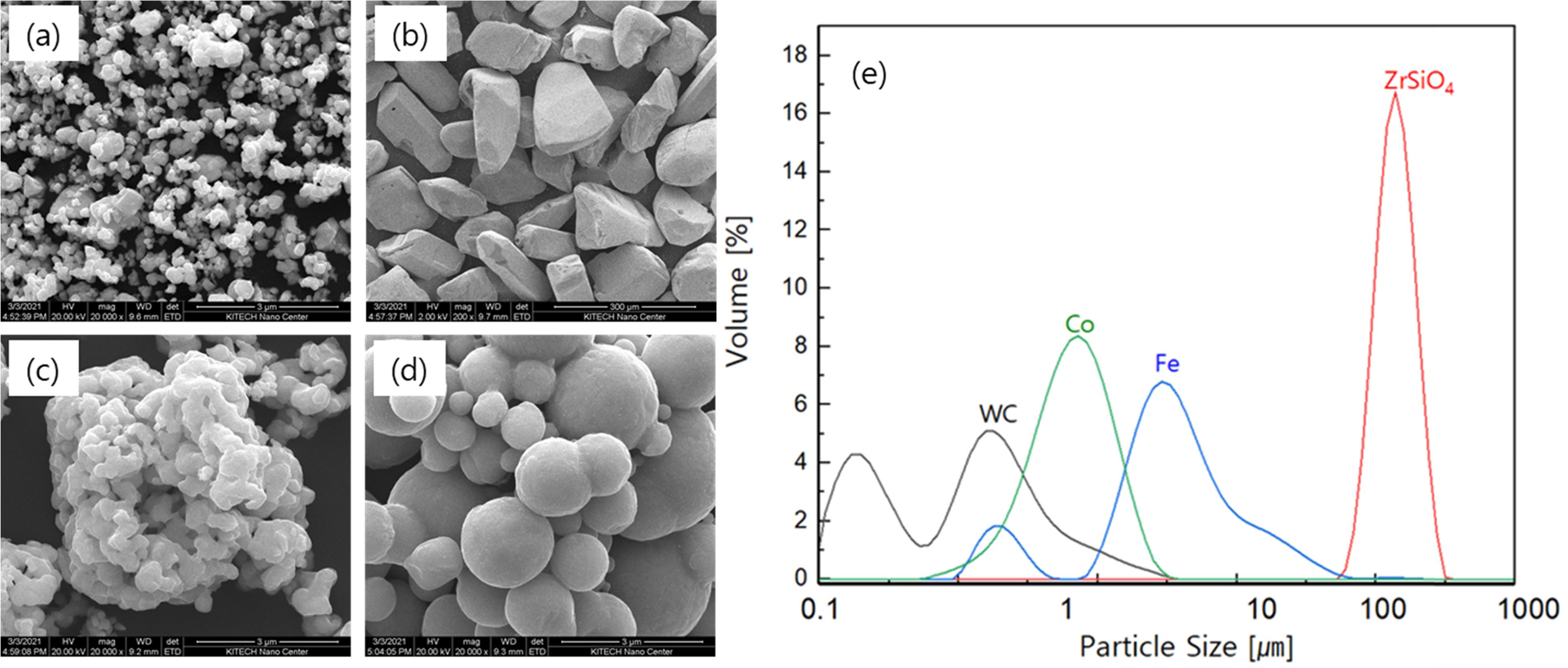
Tungsten carbide (W: 64.22 vol% and C: 35.78 vol%, ≤ 0.5 μm, TaeguTec Ltd.), cobalt (Co ≤ 2.0 μm, Alpha Ltd.), iron (Fe ≤ 10.0 μm, Alpha Ltd.), and zircon sand (ZrO2: 50.36 vol%, SiO2: 46.71 vol%, other oxides: 2.92 vol%) powders were used as the raw materials. Fig. 1 shows the micro-morphology of the starting powders by FE-SEM. The WC (see Fig. 1(a)) exhibits an angular shape, whereas Co (see Fig. 1(c)) and Fe (see Fig. 1(d)) are irregular circular types. On the other hand, ZrSiO4 (see Fig. 1(b)) has a three-dimensional columnar structure. These powders were mixed to the desired compositions, except for binderless WC, as follows: (i) WCZ-1: WC-13.15 vol% ZrSiO4, (ii) WCZ-2: WC-24.22 vol% ZrSiO4, (iii) WCoZ: WC-6.59 vol% Co-12.87 vol% ZrSiO4, (iv) WFeZ: WC-7.46 vol% Fe-12.75 vol% ZrSiO4. For reference, it is a vol% value obtained by converting the alloy composition commonly used in commercial WC-Co and WC-Fe hard materials, i.e (i) WC-5ZrSiO4 (wt.%), WC-10ZrSiO4 (wt.%), (iii) WC-5Co-5ZrSiO4 (wt.%), and (iv) WC-5Fe-5ZrSiO4 (wt.%). In order to further improve the refinement, the particles were mechanically milled by a planetary ball mill (pulverisette 5, FRITSCH Ltd.) with stainless steel vials and balls under the ratio of ball to powder of 15:1. The milling time was 12 h at 350 RPM, during which no contamination was detected in the Fe or Cr. Also, their mean particle size was measured by laser diffraction (Malvern-masterizer 2000) using Mie theory [33]. Referring to Fig.1-(e), the distribution of particle size is provided based on an average particle diameter of D (0.5), we can see the results for WC (0.48 μm), Co (1.83 μm), Fe (6.11 μm), and ZrSiO4 (128.36 μm).
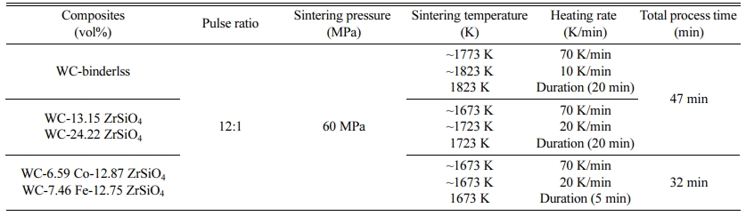
The consolidation by SPS was performed at tem- peratures from 1673 to 1823 K, using heating rates of 10, 20, and 70 K/min, and mechanical pressure of 60 MPa after fabrication of green bodies (packing) was applied in the form of uniaxial pressure on the powders. Then, the sample structural evolution was characterized by X-ray diffraction (XRD) using CuKα radiation (λ=0.154 nm). Also, the grain size and internal strain of the WC-X-Y composites were measured by Stokes and Wilson’s formula [34] using the XRD patterns:
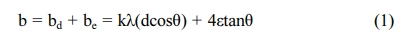
In Eq. (1), b is the Full-width at half-maximum (FWHM) of the mechanical correction value of the diffraction peak, bd and be are the measured values from the decrease in internal stress and FWHM. k is the Scherer constant of 0.9, λ is the X-ray radiation wavelength, d and ε are the measurements of the grain size and internal strain, respectively, and θ is the Bragg’s angle. Also, the grain growth according to each additive was investigated using EBSD analysis.
The temperature was monitored by IR-pyrometer, in which the shrinkage displacement of the graphite punch rod was displayed at the SPS instrument during the sintering process. The intermediate relative density (rt) during SPS with sintering time and the temperature was measured from Eq. (2) [35].
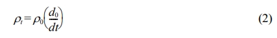
Eq. (2) is a relative density of compacts (final products) measured using the Archimedes method in distilled water from a theoretical density. d0 and dt are the thickness of the compacts after sintering and at time t. dt is calculated from the displacement of the punch rod with correction of the thermal expansion of the graphite die [35].
According to their composition, the WC-X-Y com- posites were investigated using SEM analysis to demon- strate the microstructural evolution and behavior of crack propagation. Furthermore, to compare the samples, their mechanical properties were assessed using an indentation and three-point flexural test. The hardness (MPa) and fracture toughness (MPa∙m1/2) were measure with a load of 10N (HV 10) for 15s. In order to obtain the numerical value for fracture toughness (KIC), the crack propagation lengths in the four directions of the indentations were determined to find the cracking resistance, this was calculated by the Antis [36] formula in Eq. (3):
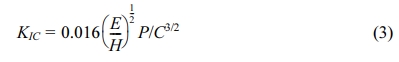
Where E is the elastic modulus (WC: 696 GPa, ZrSiO4: 255 GPa, Co: 199 GPa, Fe: 204 GPa); H is the hardness; P is the applied load; and C is the length of the crack.
A three-point flexural test was performed following the KSL 1591 standards for test specimen size (3 mm (d) x 4 mm (b) x 45 mm (L)). Under a load of 50 kN, at a rate of 0.5 mm/min. Also, the flexural stress (σ) and strain (ε) were calculated using Eq. (4):
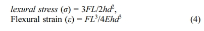
Where h is the height of specimen, d is the thickness of specimen, L is the length between both supports, E is the Elastic modulus inherent in the material, and F is the load applied at fracture.
|
Fig. 1 Micro-morphology and their particle size of (a) WC, (b) ZrSiO4, (c) Co, (d) Fe powders, and (e) distribution of particle size. |
Densification behavior of WC-(Co, Fe)-ZrSiO4 hard materials
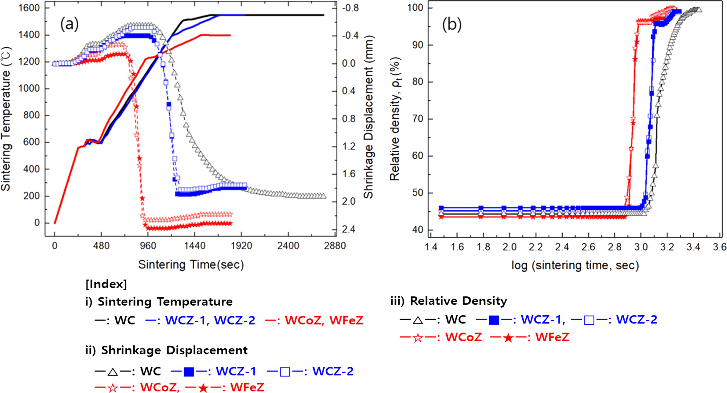
Fig. 2(a) shows the relation between sintering tem- perature and shrinkage displacement by sintering time. Depending on the constituents of the composites, there were different consolidation (or densification) profiles shown under applied temperature and pressure. It was shown that shrinkage behavior depended on the phase constituent of the binder and additive, which tended to persist up to their shrinkage saturated. The reason why the shrinkage initiation temperature differs with the presence of metallic binder phases (i.e., Co and Fe) during the solid-state diffusion could be caused by re-precipitation or rearrangement at the grain boundaries while starting to wet into the semi-liquid state while having a relatively low melting point. It is believed that the presence of binders with excellent solubility (see at 1523 K, Co: ~22 at% and Fe: ~7 at%) in WC means composites can reach the rapid densification stage at a relatively lower sintering temperature (at 1673 K) (see WC-5C-5Z: 1053 K and WC-5F-5Z: 1093 K), this is expected to come with an increase in shrinkage. In other words, the initial shrinkage characteristics are mainly determined by the wettability of the binder, where larger shrinkage rates imply superior wetting properties [37].
The other composites without binders (WC-binderless, WC-5Z, and WC-10Z) entered the rapid densification stage of shrinkage at around 1423-1443 K, where zircon does not act as a wetting agent in the grain boundaries [37]. Furthermore, the dilation behavior of composites that occurs before entering shrinkage can be considered due to the difference in the coefficient of thermal expansion between the graphite mold (1.19 μm∙m-1∙K-1) and the WC powder (5.5 μm∙m-1∙K-1). For reference, the other coefficients of thermal expansion are Co: 13.0 μm∙m-1∙K-1, Fe: 11.8 μm∙m-1∙K-1, and ZrSiO4: 4.1 μm∙m-1∙K-1.
Table 1 shows the details for the SPS process. WC-5Co-5ZrSiO4 achieved the highest relative density (100.0%). The other composites could achieve dense products close to the theoretical density limit through appropriate process control (e.g., temperature, duration, and heating rate) despite not using metallic binders. Densification behavior depends on each sample can be attributed to both the presence of a binder phase and the duration of the sintering process.
Phase composition of WC-(Co, Fe)-ZrSiO4 hard materials
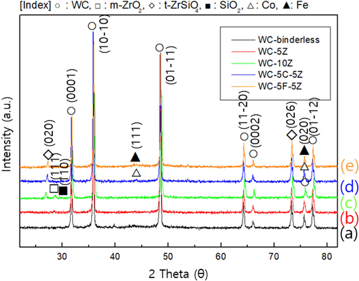
Fig. 3 shows the structural evolution of the WC-X-Y composites. Fig. 3(a) shows all the XRD peaks from WC, whereas Fig. 3(b) and (c) shows a tendency for dissociation (this takes place theoretically at 1949 K) from ZrSiO4 to ZrO2 and SiO2 because of the applied sintering temperature (occurring at 1823 K in this work). As reported by C. Curtis et al. [37], this thermal decom- position reaction begins to accelerate as temperatures rise from 1829 K, rapid cooling (and no subsequent annealing) after sintering resulted in significant residual zircon (t-ZrSiO4) without complete phase dissociation to zirconia (m-ZrO2) and silicon oxide (glassy). However, with added metallic binders, this dissociation did not occur in Fig. 3(d) and (e) when sintering was terminated at 1673 K.
Moreover, the relative peak intensity ratio [I(0001)/I(10-10)] was considered to estimate the highly oriented growth of WC grains, i.e. (10-10): prism plane and (0001): basal plane. The increase of I(0001) could lead to the abnormal preferential growth in WC grains by the adjacent to the interface of zircon-rich phase, which values (I) and average grain size were calculated to (a) 0.33 (52.70 nm), (b) 0.60 (70.79 nm), (c) 0.67 (76.36 nm), (d) 0.47 (68.46 nm), and (e) 0.52 (62.84 nm). In other words, the refined WC grains could be grown very rapidly in the basal plane, where thermodynamic instability for thermal decomposition of zircon promotes non-uniform distribution of secondary phases. Another reason could be caused by high anisotropy interfacial energy in the solidification process of the metallic binder.
Microstructural evolution and quantitative analysis
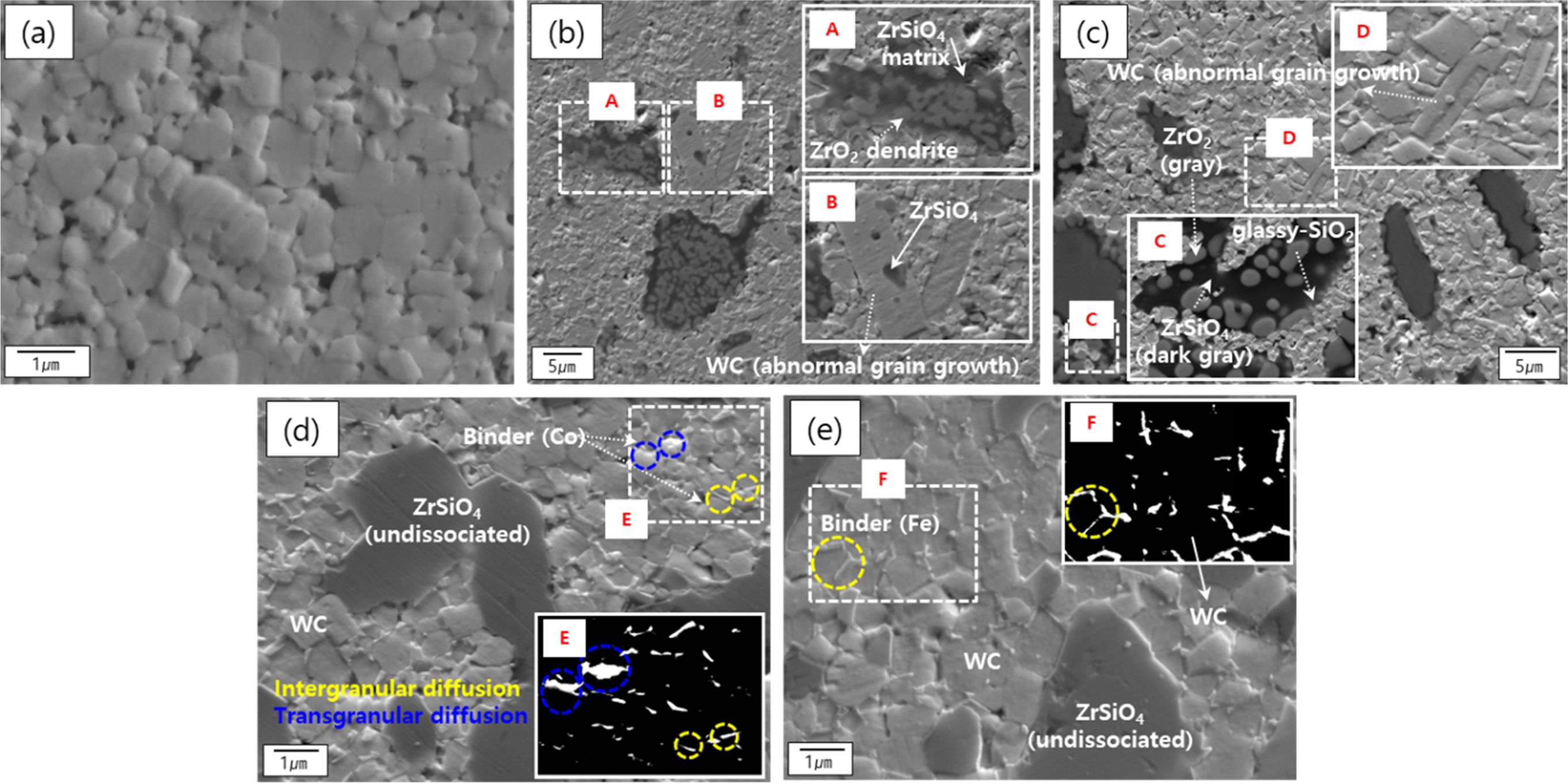
Fig. 4 shows the microstructural evolution of the WC-X-Y composites. Fig. 4(a) shows that the fine WC has a polyhedral morphology with dense grain boun- daries. Fig. 4(b) and (c) we observe the distinct distri- bution of WC with zircon. Thermal decomposition of zircon (A region) was also exhibited; we can see ZrSiO4 (matrix, dark grey) and ZrO2 (dendrite, grey). Also, abnormal grain growth in WC occurred with this dissociation of zircon. This undesirable grain growth could be caused by free carbon and microstrain (ε) [38]. Since free carbon was not found (see Fig. 3) after this sintering regime, it can be inferred that this phenomenon occurred due to higher induced micro-strain at the WC interface from the decomposition of zircon.
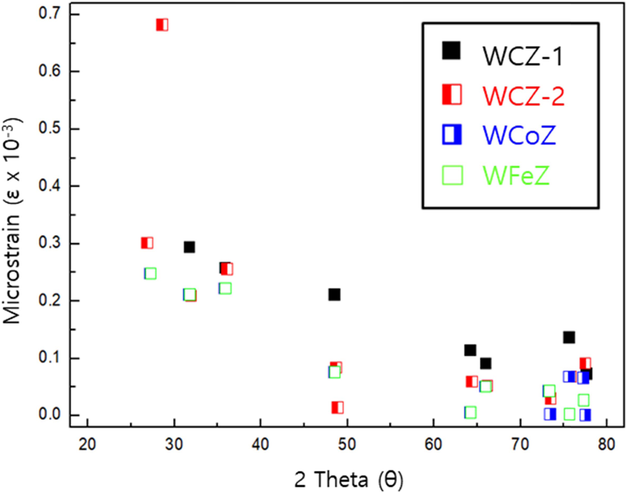
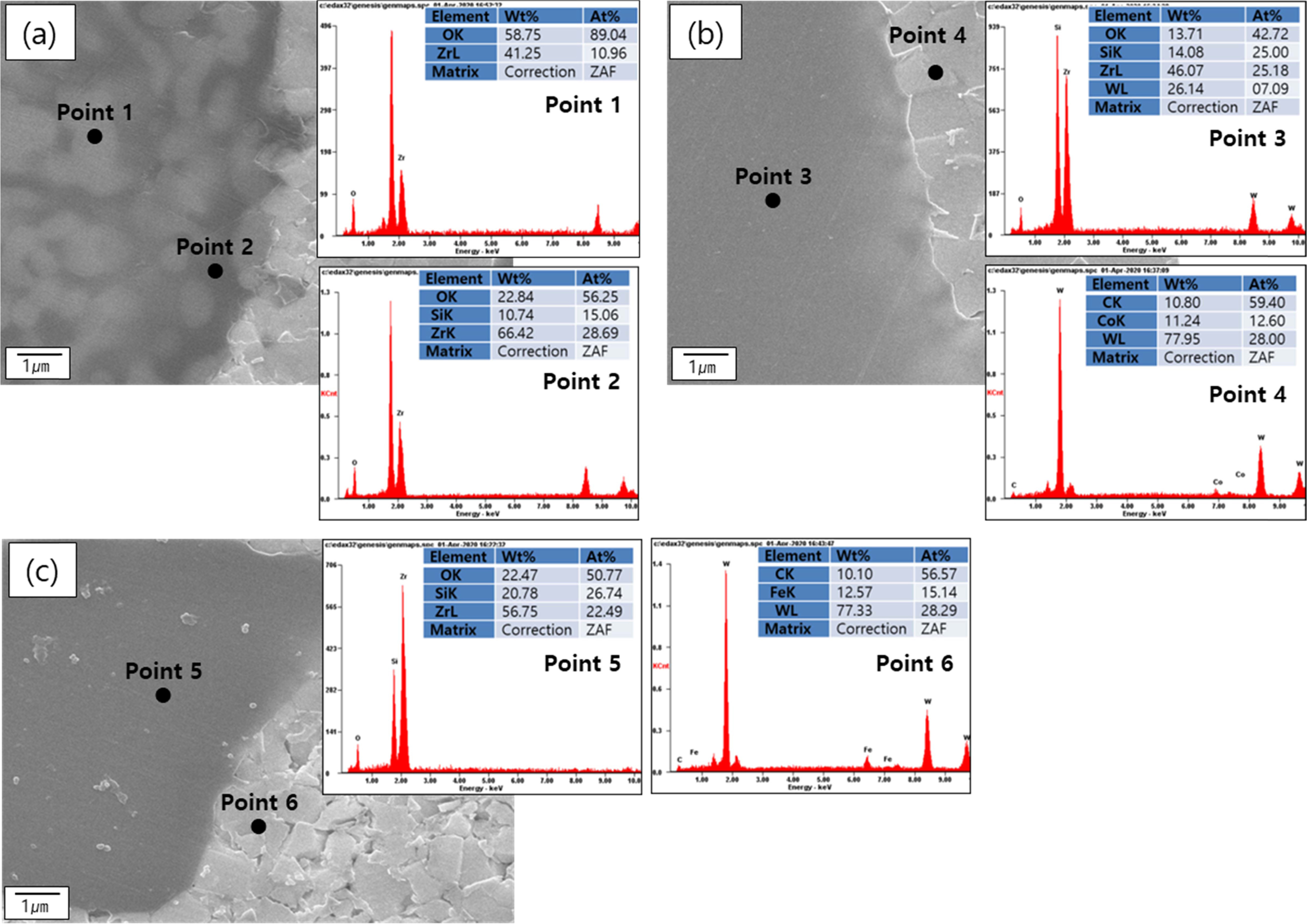
Fig. 5 indicates the variation of micro-strain measured using XRD indexing and Eq. (1). In particular, the highest strain value exhibited was 0.68 in WC-10Z, which is thought to come from the zirconia (see Fig. 3(c), at 28.61o) formed by the decomposition of zircon. In addition, it is thought that abnormal growth could be promoted in a specific plane orientation with the higher strain values among the WC grains, e.g., 0.29 at (0001)hcp in WC-5Z and 0.25 at (10-10)hcp in WC-10Z. In the case of the composites containing a metallic binder, as shown in Fig. 4(d) and (e), it was observed that homo- geneous refined grains were distributed in contrast to the abnormal grain growth. The intergranular diffusion of binders predominantly suppressed the grain growth; simultaneously, the un-dissociation of zircon gave hardly any assistance to their biased growth since it produced a low micro-strain value (ε < 0.25) for affecting WC grain boundaries. On the other hand, diffusion propagation in WC grain due to the difference in solubility of Co (~22 at%) and Fe (~7 at%) is shown by the bright regions in the insets marked E and F. It can be seen that Co, which has a significantly higher solubility in the WC grain boundaries than Fe, diffuses not only in an intergranular way but also in a trans- granular one. The quantitative analysis of the interface between the WC and several additives was carried out using SEM-EDS profile, as shown in Fig. 6. At point 1 in Fig. 6(a), we can see dissociated zircon; this indicates the ZrO2 is of dendrite morphology, whereas the profile of the matrix revealed ZrSiO4. Furthermore, at points 3 and 5, the emergence of undissociated zircon is revealed. Points 4 and 6 confirm a cemented carbide region containing concentrated rich binders, as shown in Fig. 6(b) and (c).
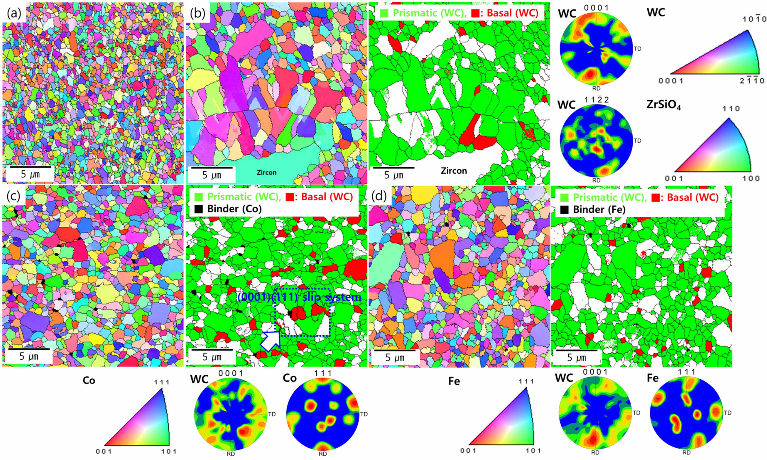
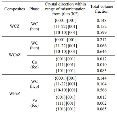
Fig. 7 shows the grain size and orientation mapping of the WC-X-Y composites observed by EBSD. In the (0001)[001] direction of the micrograph in Fig. 7(a)- (d), the variation of WC particle sizes presented are (a) 0.67 µm, (b) 1.20 µm, (c) 0.80 µm, and (d) 0.72 µm, which depend on the growth behavior of the WC grains. In Fig. 7(a), where namely solid- state sintering without binders, it might be expected to form densi- fication as a driving force for the agglomerated evolution that vanished pores between WC particles. Therefore, it is possible to suppress abnormal grain growth caused by surrounding grains by maintaining refined WC grains. However, in Fig. 7(b), the bimodal grain distri- bution of WC (i.e., abnormal & fine) is shown in the adjacent interface with zircon. Here we see that the prismatic plane is closely related to abnormal grain growth [39]. The prismatic plane has high anisotropy in stacking fault energy compared to the basal plane, where this anisotropic energy tends is to form faceted grains. Those that grew abnormally as prismatic planes (green region) are coarser than the basal planes (red region). Fig. 7(c) and (d) shows that the distribution of grains and basal planes of WC according to the binders. In particular, the WC {0001} basal plane is known to be a coherent interface plane as it is coincident with the {111} plane for FCC structures and slip systems with HCP structures [40]. In the case of the Co binder, it can be seen that their distribution was at the interface of the basal plane, so the possibility of the (0001)hcp(111)fcc slip system can be estimated. That is, the presence of this slip system may be caused in the region (see Fig. 7(c) enlarged) of the Co-binder adjacent to the basal plane of WC. This behavior is caused by inter-diffusion of Co by transgranular propagation due to its high solubility in WC grain boundaries as a binder, whereas Fe is hardly involved in the plastic deformation of WC because it has intergranular propagation [3].
Based on discussion as mentioned earlier, we cal- culated the fraction of WC (0001) plane and Co (111) plane that can form the coherent interface in the (0001) [001] direction of the WC-X-Y composites through the pole figure. The details for a fraction of (0001) and (111) planes were shown in Table 2. It can be seen that the volume fraction of WCoZ than WFeZ. Thus, it is clear that WCoZ has the highest probability of ductility among the presented WC-X-Y composites.
Mechanical properties of WC-(Co, Fe)-ZrSiO4 hard materials
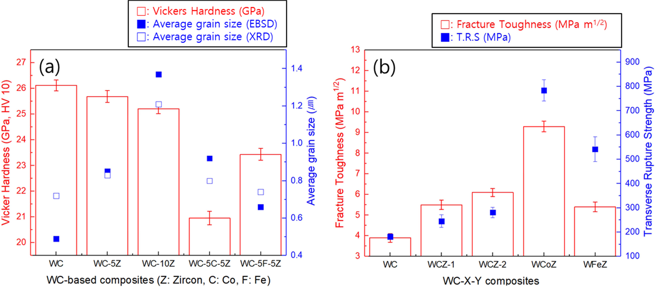
Fig. 8 and 9 show the mechanical properties and crack propagation of the WC-X-Y composites. Based on the WC grain size, measured by various methods, those with added zircon, the hardness characteristics were determined according to the grain size, as shown in Fig. 8(a). With increasing zircon contents, the hardness gradually decreases (26.11 GPa to 25.21 GPa). Additionally, the mechanical properties of those composites with added binders were also affected by the coherent interface state. In other words, it was found that the higher the intergranular diffusion from added Fe, the more grain growth of WC was suppressed (0.91 µm to 0.66 µm), and the hardness increased (20.95 GPa to 23.43 GPa) considerably.
The influence of the zircon addition and metallic binders on the fracture toughness-transverse rupture strength (T.R.S) of the WC hard materials was shown in Fig. 8(b). It can be seen that the specimen with added Co has the highest fracture toughness (9.2 MPa·m1/2) and T.R.S (784.1 MPa) values, this implies that its coherent interface gives a region of enhanced interfacial resistance, where crack propagation from a transgranular fracture can be absorbed, as shown in Fig. 9(c). In addition, the interaction between the twin boundaries and dislocations in the coherent interface may gradually exhibit dominance to their work hardening [41]. In other words, if the twining continues deformation due to their sliding dislocations under plastic deformation, the dislocation movement is relatively slowed, which is required a more extensive load to generate additional plastic deformation [42]. Consequently, we see a strain strengthening effect enhancing the transverse rupture strength.
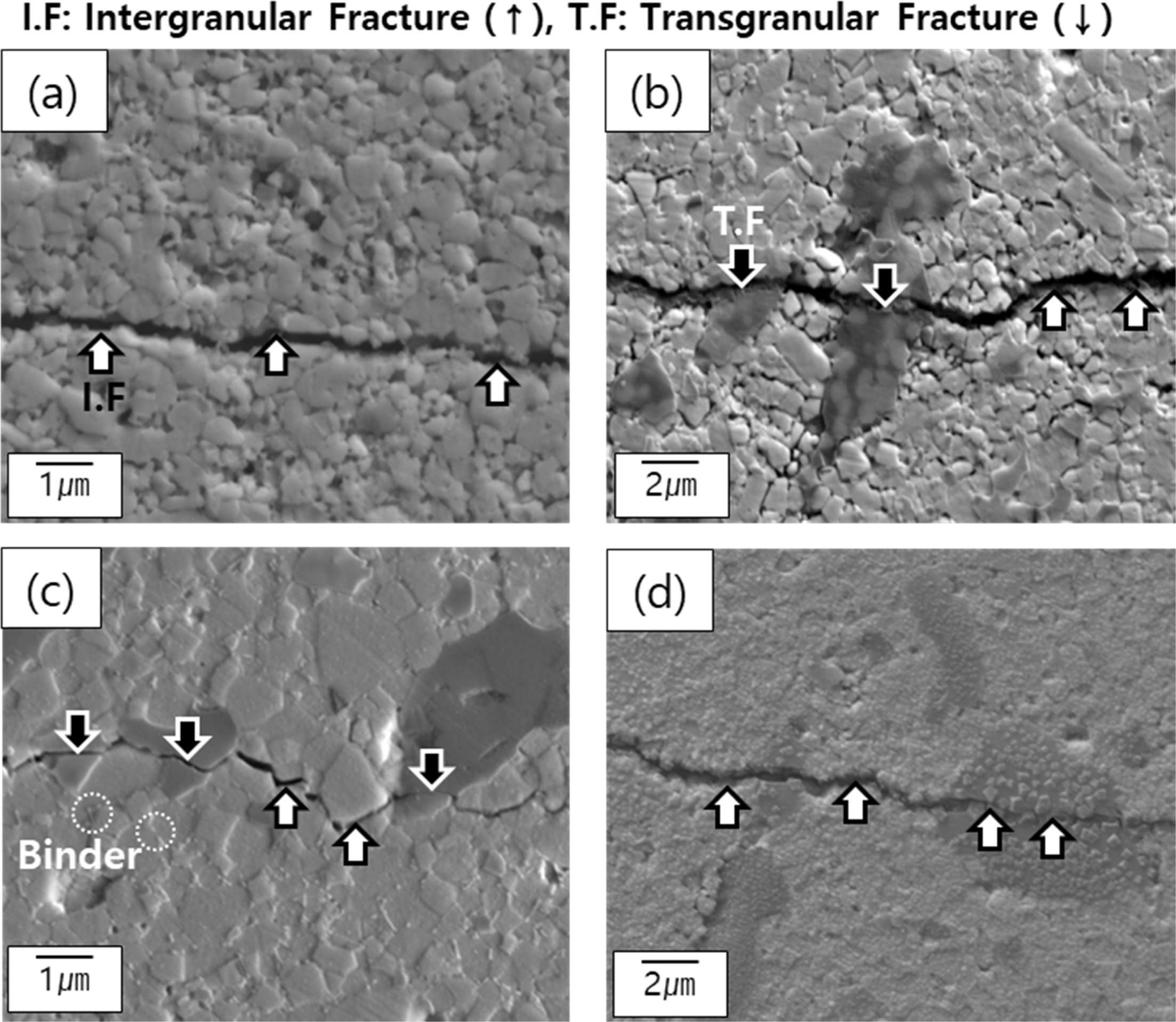
The addition of zircon improves (3.9 MPa·m1/2 to 6.1 MPa·m1/2) the brittleness of WC slightly. That is, transgranular fracture behavior (see Fig. 9(b)) propagated to dissociated zirconia upon fracture behavior rather than the formation of a coherent interface. Also, the addition of Fe, despite its inherent low Young's modulus (204 GPa), doesn’t cause any significant improvement of fracture toughness (5.4 MPa·m1/2) because the tendency is for intergranular fracture (see Fig. 9(d)) of the refined grains formed by grain refinement. On the other hand, the only intergranular crack as the fracture proceeds at the grain boundaries at WC grains without binder phases (see Fig. 9(a)).
|
Fig. 2 Schematic representation of WC-X-Y composites with during spark plasma sintering: (a) temperature-shrinkage displacement profile and (b) variation of relative density. |
|
Fig. 3 XRD patterns of WC-X-Y composites: (a) WC, (b) WCZ1, (c) WCZ-2, (d) WCoZ, and (e) WFeZ |
|
Fig. 4 Microstructural evolution of WC-X-Y composites: (a) WC, (b) WCZ-1, (c) WCZ-2, (d) WCoZ, and (e) WFeZ. |
|
Fig. 5 Variation of micro-strain of WC-X-Y composites |
|
Fig. 6 SEM-EDS images at interface of WC/precursors: (a) WC/ZrSiO4 (dissociated), (b) WC-Co/ZrSiO4 (undissociated), and (c) WC-Fe/ ZrSiO4 (undissociated). |
|
Fig. 7 EBSD analysis and pole figures of WC-X-Y composites: (a) WC, (b) WCZ, (c) WCoZ, and (d) WFeZ. |
|
Fig. 8 Mechanical properties of WC-X-Y composites: variation of a) hardness-grain size and b) fracture toughness/transverse rupture strength. |
|
Fig. 9 Micro-crack propagation of WC-X-Y composites: (a) WC, (b) WCZ (dissociated), (c) WCoZ (undissociated), and (d) WfeZ (undissociated). |
|
Table 2 Volume fraction of (0001) pole figure in WC-X-Y composites of the major crystal direction. |
In this work, the microstructural behavior and mechanical properties of WC-based hard materials with different additive materials (i.e., zircon, cobalt, and ferrite) were investigated using several approaches.
Our work leads to the following conclusions:
(1) The densified compacts of WC-binderless, WC-13.15 vol% ZrSiO4, WC-24.22 vol% ZrSiO4, WC-6.59 vol% Co-12.87 vol% ZrSiO4, and WC-7.46 vol% Fe-12.75 vol% ZrSiO4 composites were achieved using spark plasma sintering with various applied temperatures.
(2) The microstructural behavior of WC-based com- posites was investigated; we looked at the disso- ciation of zircon and distribution of binder in terms of their orientation in the planes of WC, i.e., prismatic and basal.
(3) The specimens’ mechanical properties were mainly determined by two factors. First, the grain size depended on the state of the WC grain boundaries. Second, fracture behavior (i.e., crack propagation) is related to forming of a coherent interface with the metallic binder (i.e. Co and Fe). The highest hardness value of 26.11 GPa was exhibited in the WC-binderless sample without any additives. In contrast, to improve fracture toughness at the work hardening from the addition of Co phase, the highest fracture toughness value was evident when their transgranular frac- ture and plastic deformation characteristics were shown. The nominal composition for high toughness (9.2 MPa·m1/2) is WC-6.59 vol% Co-12.87 vol% ZrSiO4. Consequently, novel cemented carbide composites for the most appropriate mechanical properties with added zircon were fabricated; these materials are cheaper than conventional hard materials but also have competitive mechanical properties, for instance, a hardness of 25.21 GPa, fracture toughness of 6.1 MPa·m1/2, and transverse rupture strength of 281 MPa were recorded for WC-24.22 vol% ZrSiO4.
This study has been conducted with the support of the Korea Institute of Industrial Technology as “Production technology commercialization project” (KITECH EH-21-025).
- 1. H.K. Park, H.J. Youn, S.N. Lee, H.S. Bang, and I.H. Oh, J. Ceram. Process. Res. 12[3] (2011) 304-309.
- 2. H. C. A. Chee, R. S. K. Singh, and K. Y. Lee, J. Ceram. Process. Res., 21[4] (2020) 495-500.
-

- 3. J.H. Lee, I.H. Oh, J.H. Jang, S.K. Hong, and H.K. Park, J. Alloys Comp. 797 (2019) 1-10.
- 4. I.J. Shon, I.H. Oh, J.H. Ryu, J.H. Jang, H.J. Youn, and H.K. Park, J. Ceram. Process. Res. 14[5] (2013) 641-647.
- 5. S. Miao, Z. Xie, Y. Lin, Q. Fang, J. Tan, and Y. Zhao, Metals 10 (2020) 277.
-
- 6. J. Chen, M. Gong, and S. Hua, J. Ceram. Process. Res., 16[2] (2015) 244-248.
- 7. F. Djematene, B. Djerdjare, A.R. Boukantar, A. Rezzoug, S. Abdi, I. Daoud, and A. L. Ortiz, J. Asian. Ceram. Soc. 8[4] (2020) 1043-1050.
-
- 8. B. Wang, J. Jia, Z. Wang, Z. Yin, L. Huang, and J. Yuan, Ceram. Int. 47[6] (2021) 8322-8329.
-
- 9. S. Grasso, J. Poetscheke, V. Richter, G. Maizza, Y. Sakka, and M.J. Reece, J. Am. Ceram. Soc. 96 (2013) 1702-1705.
-
- 10. A. Nasser, M. Kassem, A. Elsayed, M.A. Gepreel, and A. Abdelmoneim, J. Mater. Eng. Perform. 25 (2016) 5065-5075.
-
- 11. D. Ma, Z. Kou, Y. Liu, Y. Wang, S. Gao, X. Luo, W. Li, Y. Wang, Y. Du, and L. Lei, Int. J. Refract. Met. H. 54 (2016) 427-432.
-
- 12. H.C. Kim, J.K. Yoon, J.M. Doh, I.Y. Ko, and I.J. Shon Mater. Sci. Eng. A 435 (2006) 717-724.
-
- 13. H.K. Park, J.H. Lee, J.H. Jang, and I.H. Oh, Kor. J. Met. Mater. 57 (2019) 304-309.
-
- 14. J.S. Choi, J.H. Kim, J.U. Hur, S.C. Choi, and G.S. An, J. Ceram. Process. Res. 21[3] (2020) 351-357.
-
- 15. W. K. Jung, J. W. Hong, and D. H. Choi, J. Ceram. Process. Res. 22[1] (2021) 86-90.
-
- 16. J. S. Choi, J. H. Kim, J. U. Hur, S. C. Choi, and G. S. An, J. Ceram. Process. Res. 21[3] (2020) 351-357.
-
- 17. C. W. Park, J. H. Park, H. S. Kang, H. A. Lee, J. H. Lee, J. H. In, and K. B. Shim, J. Ceram. Process. Res. 19[5] (2018) 383-387.
- 18. Y. Gao, K. Gao, L. Fan, F. Yang, X. Guo, R. Zhang, and L. An, Ceram. Int. 46[8] (2020) 12727-12731.
-
- 19. M. Padmakumar and D. Dinakaran, Mater. Manuf. Process. 36[6] (2021) 637-659.
-
- 20. A.H. Musfirah, J.A. Ghani, and C.H. Haron, Wear 376 (2017) 125-133.
-
- 21. D. Kumar, S. Idapalapati, W. Wang, and S. Narashimalu, Materials 12 (2019) 503.
-
- 22. T. Bai and T. Xie, Mater. Chem. Phys. 20 (2017) 113-119.
-
- 23. S.N. Grigoriev, S.N. Fedorov, and K. Hamdy, Manufac- turing Rev. 19 (2019) 27.
-
- 24. B. Basu, T. Venkateswaran, and D. Sarkar, J. Eur. Ceram. Soc. 25 (2005) 1603-1610.
-
- 25. B.R. Golla and B. Basu, in “Spark Plasma Sintering of Nanoceramic Composites.” (Comprehensive Hard Materials, 2014), pp. 177-205.
-
- 26. Y. Sun, H. Wu, M. Li, Q. Meng, K. Gao, X. Lu, and B. Liu, Materials 9 (2016) 343.
-
- 27. T. Langa, P. Olubambi, T. Shabalala, and M.B. Shongwe, Int. J. Refract. Met. H. 72 (2018) 341-348.
-
- 28. M. Roosta, H. Baharvandi, and H. Abdizade, Int. J. Refract. Met. H. 29 (2011) 710-715.
-
- 29. N.M. Rendtorff, S. Grasso, C. Hu, G. Suarez, E.F. Aglietti, and Y. Sakka, Ceram. Int. 38 (2012) 1793-1799.
-
- 30. S. Yugeswaran, P.V. Ananthapadmanabhan, T.K. Thiyagarajan, and K. Ramachandran, Ceram. Int. 41 (2015) 9585-9592.
-
- 31. N.M. Rendtorff, G. Suarez, M.S. Conconi, S.K. Singh, and E.F. Aglietti, Procedia Mater. Sci. 1 (2012) 337-342.
-
- 32. L.D. Kock, M.D.S. Lekgoathi, E. Snyders, J.B. Wagner, J.T. Nel, and J.L. Havenga, J. Raman Spectro. 43 (2012) 769-773.
-
- 33. E.G. Wriggleworth and J.H. Johnston, Nanoscale Adv. 3 (2021) 3530-3536.
-
- 34. V. Ziv and S. Weiner, J. Connective Tissue Research 30 (1996) 165.
-
- 35. L. An, A. Ito, and T. Goto, J. Asian Ceram. Soc. 2 (2014) 154-157.
-
- 36. G.R. Antis, P. Chantikul, B.R. Lawn, and D.B. Marshall, J. Am. Ceram. Soc. 64 (1981) 533-538.
-
- 37. M.A. Gren and G. Wahnstrom, Materialia 8 (2019) 100470.
-
- 38. J. Poetscheke, V. Richter, T. Gestrich, and A. Michaelis, Int. J. Refract. Met. H. 43 (2014) 309-316.
-
- 39. R. He, Q. Yang, B. Li, J. Lou, H. Yang, and J. Ruan, J. Ruan 805 (2021) 140586.
-
- 40. C. Wei, X. Song, J. Fu, X. Liu, H. Wang, Y. Gao, and Y. Wang, Cryst. Eng. Comm. 15 (2013) 3305-3307.
-
- 41. L. Sun, X. He, and J. Lu, Npj Comput. Mater. 4 (2018) 1-18.
-
- 42. N.T. Selli, J. Ceram. Process. Res. 21[6] (2020) 632-639.
-
 This Article
-
2021; 22(6): 655-664
Published on Dec 31, 2021
- 10.36410/jcpr.2021.22.6.655
- Received on May 24, 2021
- Revised on Jul 2, 2021
- Accepted on Jul 17, 2021
Services
- Abstract
introduction
experimental procedure
results and discussion
conclusion
- Acknowledgements
- References
- Full Text PDF
Shared
Correspondence to
- Hyun-Kuk Park
-
Korea Institute of Industrial Technology (KITECH), Smart Mobility Materials and Components R&D Group, 6, Cheomdan-gwagiro 208-gil, Buk-gu, Gwang-Ju, 61012, Korea
Tel : +82 62 600 6270 Fax: +82 62 600 6149 - E-mail: hk-park@kitech.re.kr
Clean-Energy Research Institute(CRI), Hanyang University, 222, Wangsimni-ro, Seongdong-gu, Seoul, 04763, Korea
E-mail: jcpr@hanyang.ac.kr