


- Investigations on properties of ceno PCM produced via sonication process for thermal comfort building
R. Greesana,*, C. Mekalab and M. Ravichandranc
aDepartment of Civil Engineering, MahathAmma Institute of Engineering & Technology, Pudukkottai, 622005, Tamil Nadu, India
bSubject Matter Expert, Civil Engineering, Edu Tech Department, Larsen and Toubro Ltd, Chennai, 600089, Tamil Nadu, India
cDepartment of Mechanical Engineering, K.Ramakrishnan College of Engineering, Trichy, 621 112, Tamil Nadu, IndiaThis article is an open access article distributed under the terms of the Creative Commons Attribution Non-Commercial License (http://creativecommons.org/licenses/by-nc/4.0) which permits unrestricted non-commercial use, distribution, and reproduction in any medium, provided the original work is properly cited.
The sustainable development can be achieved by means of optimal usage of energy in each and every industry. According to our building sector, eco-friendly construction is achieved by utilizing the resources in right way with minimal wastage and maximum usage. The Phase Change Material is such a solution to build an energy efficient building with minimal consumption of energy resources because of its thermal characteristics. The paper revealed the usage of encapsulated PCM in building construction to achieve thermal stability structure without affecting its strength and durability. Sonication method is implemented to make a encapsulated PCM called Ceno-PCM. For the composite sample, cenosphere of 100 µm is mixed thoroughly with liquid paraffin under ultrasonic heat waves and the sample specimen shows the better results after it getting dried in oven up to 80ºC. The experimental investigations are examined through FESEM EDX, TGA etc, to observe the performance of the sample and it also gives the appreciable results. Mechanical properties are examined through the respective testing with the mortar specimen of different percentage level of Composite PCM and the results are summarized to conclude the optimal level of PCM
Keywords: PCM, Cenosphere, Paraffin, Thermal Performance, Material Analysis
The construction industry is one of largest energy consuming sectors. So as like as other sectors, con- struction industry is also in a need of speedy response over energy efficiency. It is necessary to control the rapid depletion of resources, energy scarcity by finding the suitable solution for the sustainable development. In Some of the developing countries like India, the construction activities are in huge development because of rapid urbanisation and rising population. So it is primary to innovate the optimum one for energy con- servation.Regarding the climatic conditions, residential buildings are most sensitive because of the thermal performance. Building envelopes place vital role as interface between indoor and outdoor environment to prevent the loss of energy irrespective of weathering effects [1, 2].
The statement from world business council of sustainable development shows that, as much as 40% of energy is consumed by building sector alone [3]. PCM's are nothing but the material which can change their state from one to other because of phase changing temperature and it's character of tend to change on the behaviour. MEPCM’s exhibit several advantages such as their chemically-inert nature, optimized heat transfer and its ability to be mixed with other materials [4-7].
Various extensive studies showed as, PCM's are the better choice for optimal usage of energy and to built a green building environment.[8] Few drawback may result in the bulk usage of PCM’s, while incorporate with construction materials. So it is preferable to do two methods namely, encapsulation of PCM and form-stable PCM composites [9]. Microencapsulation of PCM is not only to avoid the leakage and but also to improve thermal performances without reducing other proportion PCM needs to capsulate, when they are used with building materials like concrete, plaster etc. The microcapsules are mostly in a spiral shape of few micrometers in size [10].
At a particular transition temperature, PCM may subject to alter their phase and it may results in releasing of huge amount of energy. And when the value of temperature may goes beyond the level, the polimeric shell may lose its thermal stability. So it is more difficult to exchange the temperature between the PCM and the environment [10, 11]. The leakage of PCMs can’t be arrested due to the absence of protective layer on the porous materials which can absorb PCM. To facilitate various function of PCM in construction, the barriers are rectified by encapsulating PCM in hollow fly ash particle called Cenosphere. Now the encapsulated material will expose high value of stiffness, strength and a thickness of few micrometers [12]. An ideal PCM loaded perforated cenosphere can be made to use after the removal of glass-crystalline nanosized film on the cenosphere by implementing acid etching. And to control leakage of PCM ,a microlayer of silica coating is applied to Ceno PCM. For the past one decade, the PCM's and it's applications are in trend to make an energy efficient building. The possible incorporation of phase change materials (PCMs) in building has made more attention in research due to the concern on global warming. The optimal consumption of energy leads to sustainable development of environment and to avoid the over dosage of energy in building sectors. Due to high heat of fusion PCM may tend to store and release large amount of thermal energy at time of melting and solidifying process. [13].
Phase change materials should be used for building applications may be Organic or in-organic in nature. As compare with in-organic, organic PCM is recommended in most of the studies due to its multiple advantages such as, large latent heat capacity, sustainable thermal stability, chemically inert [14]. Because of the unique spherical shape of cenosphere, it makes the lowest surface area to volume ratios and hence less amount of is needed to wet out the surface and develop the nature of workability [15].
In this work, Liquid Paraffin of Heavy Grade was selected because of its good performance and its easy availability in nature to manufacture CenoPCM. Futher- more, microencapsulation is a significant technique act as a physical barrier between a core and other com- ponents of products [16, 17]. It is observed that the emplacement of PCM makes a solution to overheating problem by means of increasing the thermal mass of a building with latent heat capacity of phase change materials [18, 19].
The major characterization studies like SEM, EDX, TGA, XRD are analysed the properties and the perfor- mance of Cenosphere loaded PCM. A cement mortar loaded with a synthesized Ceno PCM was developed and evaluated for finding its compressive strength. These investigation results showed the better performance of the CenoPCM in all the aspects like, morphology, mechanical and thermal properties.
Materials
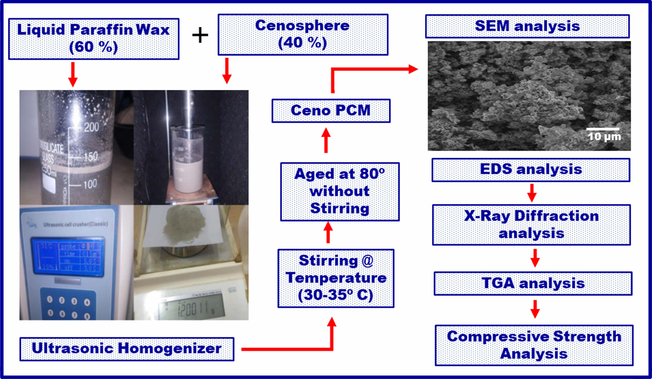
Paraffin is one of the most suitable material because of its several advantages as ease availability, less toxic, more heat capacity and chemically inert in nature. The liquid paraffin of heavy grade was purchased from SRL Pvt. Ltd, Mumbai with the following specifications. The appearance of the liquid paraffin is clear and colorless in the form of viscous (110-230 mpass). The density is 0.860-0.904 g/mL. Cenosphere are one of the most perfect ingredients obtained from coal fly ash to be used along with other building materials like concrete, mortar, plaster. It is generally hollow spherical in struc- ture and it can be applied in many industrial application due to its superior properties such as, chemical inertness, excellent insulation, low bulk density, high thermal resistance, high workability & Strength. In the chemical composition of 300 µm sized Cenosphere, SiO2 & Al2O3 place a major contribution [20]. Fig. 1 shows the complete experimental plan of the present study.
Synthesis of Ceno-PCM
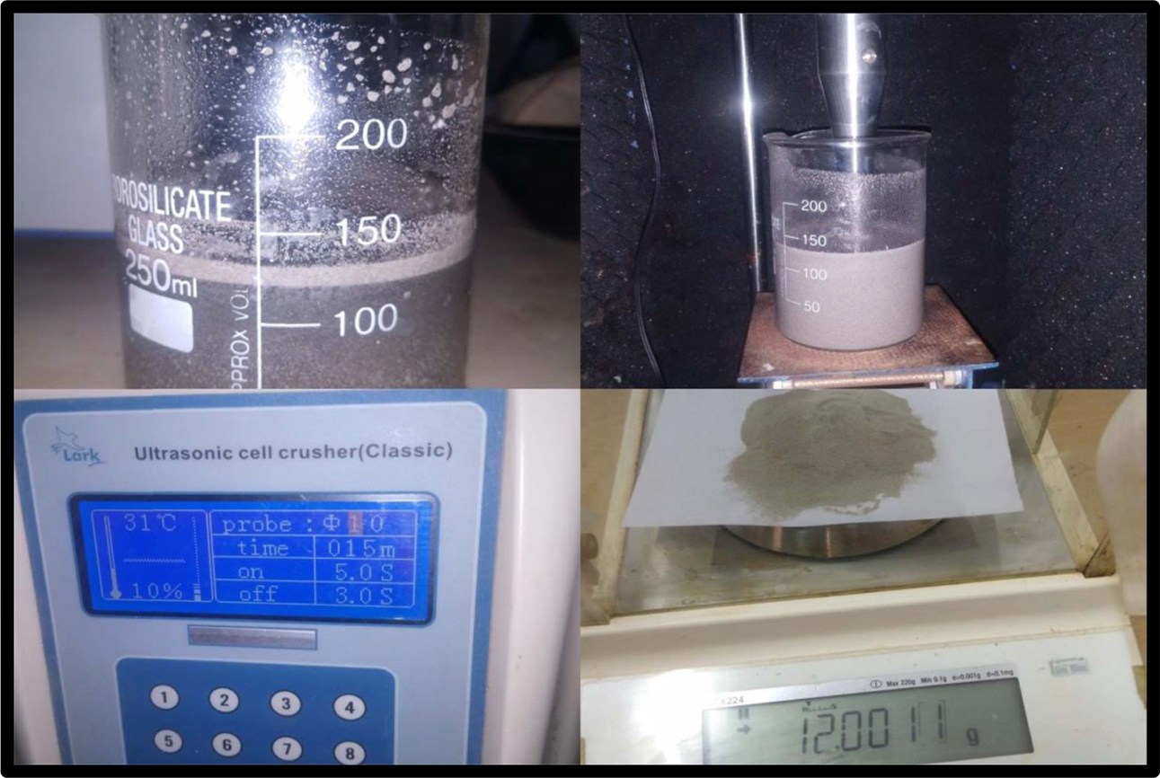
A liquid paraffin is micro encapsulated with ceno- sphere were synthesized through ultrasonic heat waves via sonication process. A typical synthetic procedure is described as follows. In one beaker 60% of liquid paraffin is taken and it is stirred with 40% of Cenosphere using ultrasonic homogenizer. Using of ultrasonic heat waves the materials are stirred vigorously at a temper- ature range of 30 ºC to 35 ºC with the probes frequency as 5 sec. it takes up to 20 min time for the synthesis of cenopcm. Then the suspension solution obtained was continuously heated up to 80 ºC and aged for an hour without agitation. Finally, the microencapsulated Ceno PCM was obtained as some white powders by filtration. The obtained powder was washed and collected for further characterization & testing. Fig. 2 shows the preparation process of Ceno-PCM.
Characterization and properties
FESEM (Field Emission Scanning Electron Microscopy) scans a focused electron beam over a surface of the sample which is underwent for SEM analysis. The technique is used for observing the surface morphology of our obtained Ceno PCM and the images were taken with a Vega3TESCAN microscope. And the elemental composition of PCM was obtained through the technique called EDX analysis (Energy Dispersive X-Ray). With respect to the ingredients present in the samples, the EDX spectra showed the peak margin. The thermal analysis of availed samples like thermal stability, reliability, conductivity was done through TGA – Thermo Gravimetricalf Analysis. Compression Testing Machine is involved to examine the strength parameter of mortar cubes with PCM.
Preparation of specimen
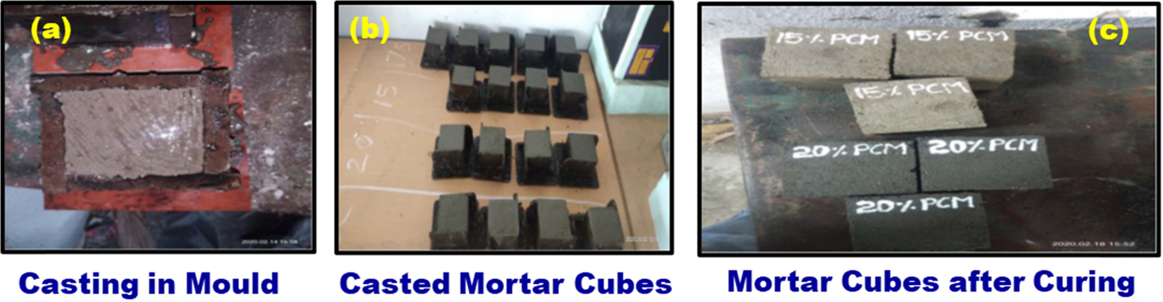
The moulds of 70 mm x 70 mm x 70 mm were taken to cast a mortar mixture in two layers and each layer was compacted by using a specified tamping rod, to avoid the effects of voids and honey combs. During the casting of mortar specimen, for an effective and economical usage of mortar, small trowels are used to collect the mortar without any wastage. Casting of mortar cubes are shown in Fig. 3(a-c). The preparation process consisted of preparing four batches of mortar each containing various percentages of PCM added at various proportions to find out the appropriate percentage to suit the requirement. The prepared specimens were allowed to curing for 28 days, out of which samples are taken out for 7 days, 14 days and 28 days for early and final compressive strength determinations.
|
Fig. 1 Work plan for the present study. |
|
Fig. 2 Preparation of Ceno-PCM. |
|
Fig. 3 (a-c) Casting of mortar cubes in moulds and prepared samples. |
Surface morphology & element analysis
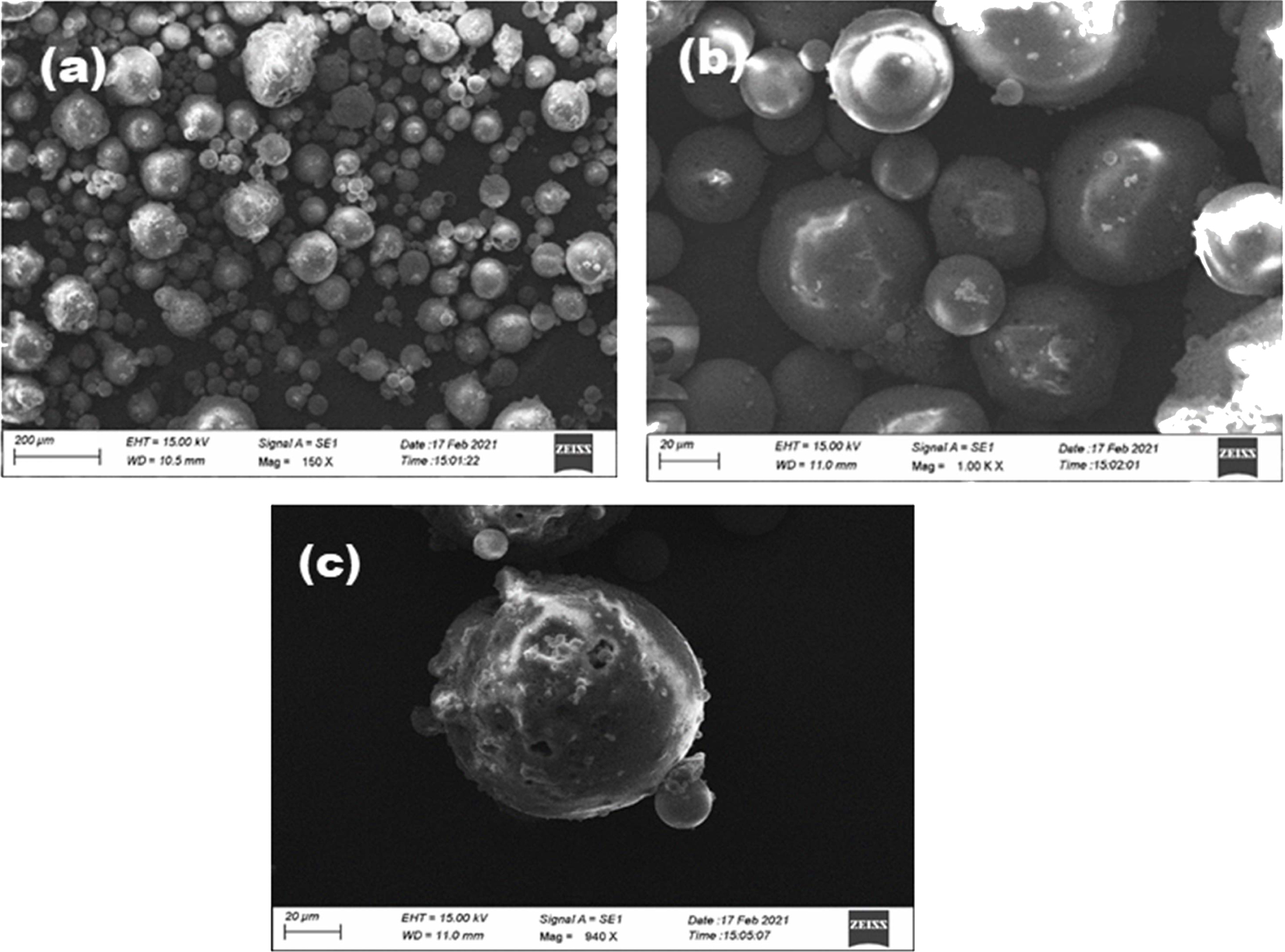
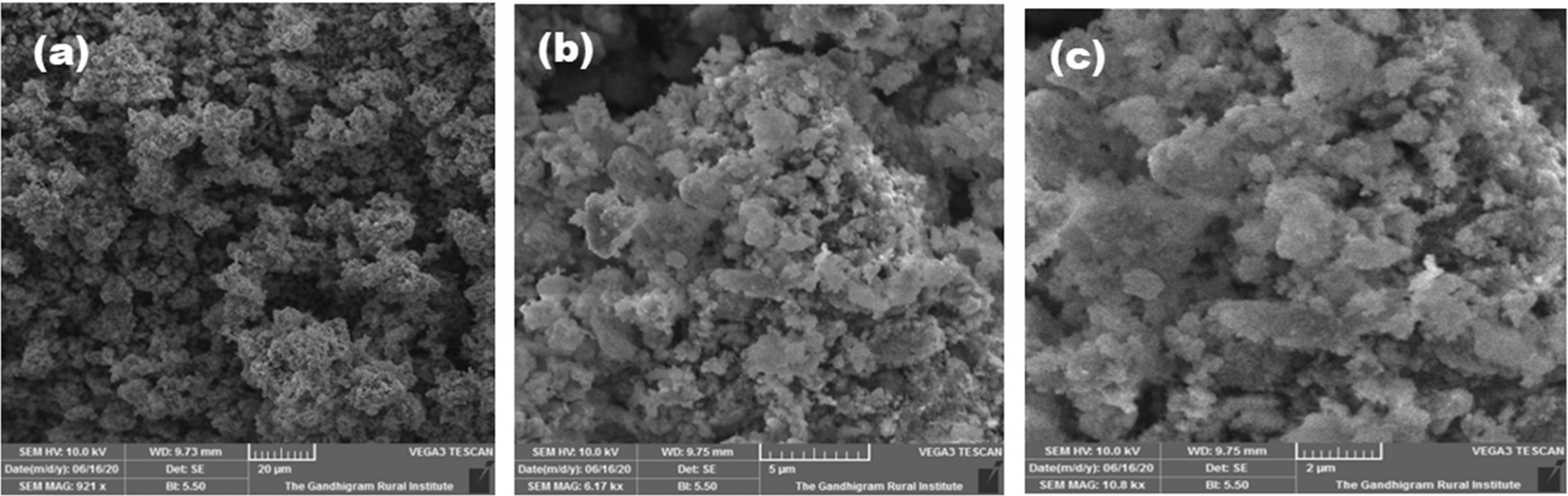
Fig. 4(a-c) shows the SEM images of Cenosphere at various scale and magnification. The morphology of the as received Cenosphere is analyzed using SEM and it clearly shows the regular spherical in shape. From the SEM analysis it is clearly observed that, the size of the powders is less than 100 μm in size.
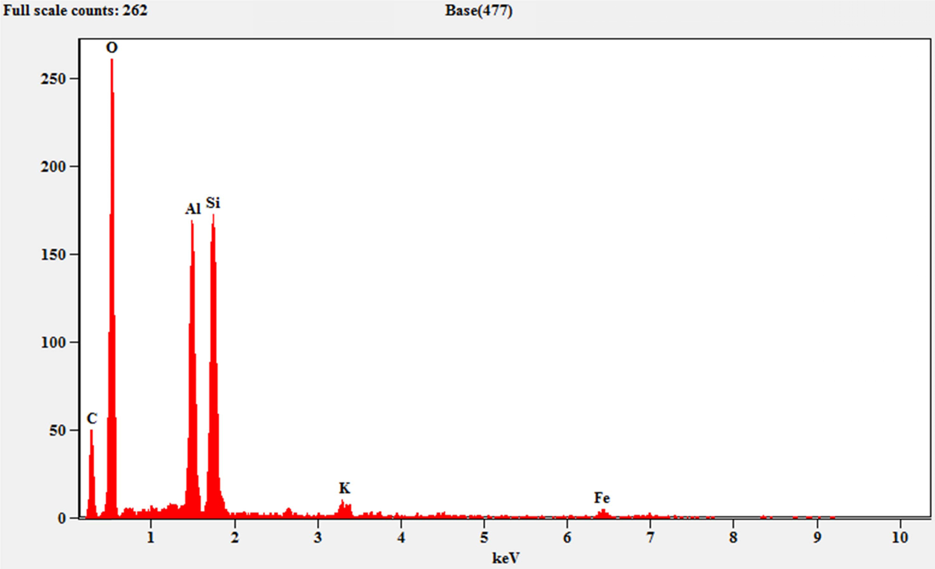
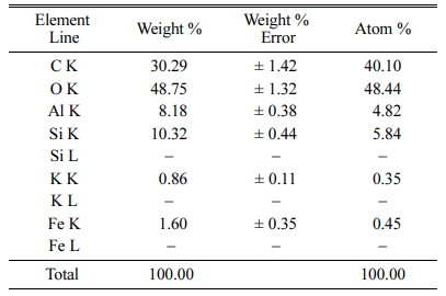
Fig. 5 shows the EDS result of Cenosphere. The com- position of the Cenosphere is provided in Table 1 along with weight percentage and atomic percentage of ele- ments present in the cenosphere. The major elements are identified as C (30.29%), O (48.75%) and Si (10.32%).
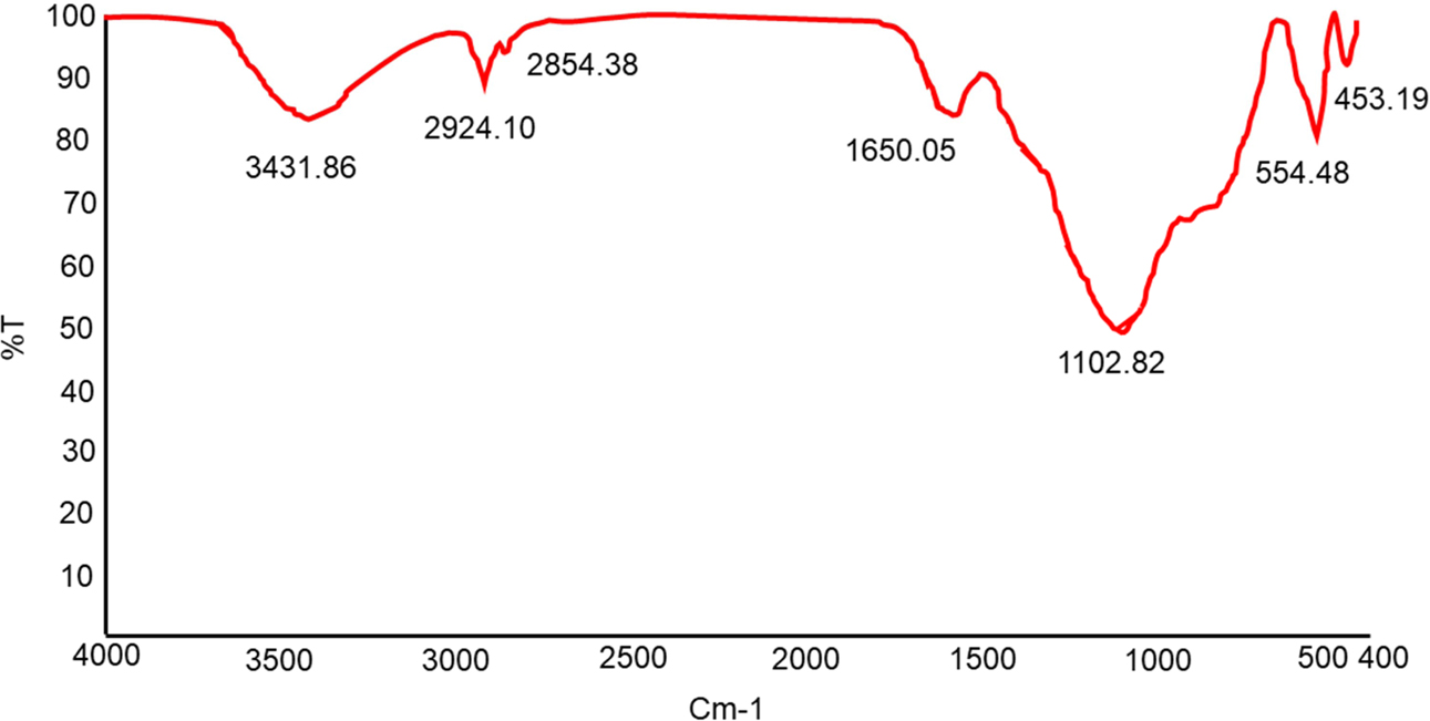
Fig. 6 shows the FTIR spectra for chemosphere and the peak at 1102.82 cm−1 ensures the Si-O-Si stretching. Asymmetric stretching of Si-O-Al os observed at the peak of 554.48 cm−1. Another hydroxyl group of silanols is evident at a peak of 3431.86 cm−1. A band due to alkane medium (C- H) stretch is observed at 2854.38 cm-1. C-H stretching of CH2, is noted in the absorption band of 2924.10 cm–1.
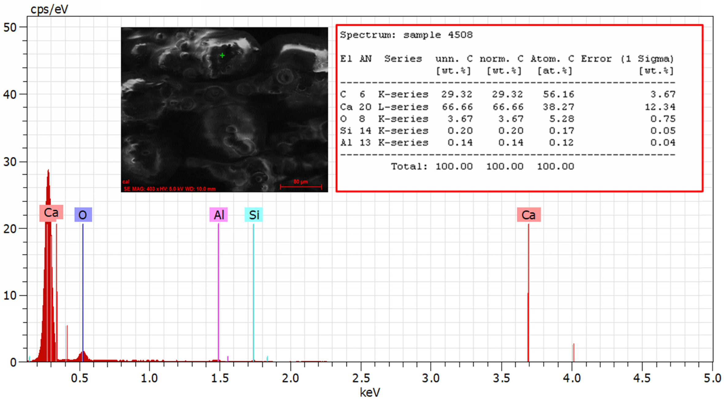
The FESEM photographs of microencapsulated PCM’s are shown in Fig. 7(a-c). The change in morphology is observed for the Ceno PCM when compare with as received Cenosphere (Fig. 4). The spherical morphology of the Cenosphere is completely changed and the size of the particles also decreased. The decrease in size of the particle is favor to improve the properties of the casted mortar cube. The porosity of the cube could be improved by the inclusion of small size Ceno PCM particles. The SEM images show the well-controlled morphology of the Ceno PCM and this is due to the proper processing of liquid paraffin wax with Cenosphere by suitable method. The EDX test results shown in Fig. 8 and it confirms the elemental composition of Ceno PCM. The peak structure of Ca, C elements appear in the graph showed that, these are all the major ingredients present in the as synthesized Ceno PCM. The higher weight percentage of Ca is presented in the as synthesized Ceno PCM and it is observed as 66.66%.
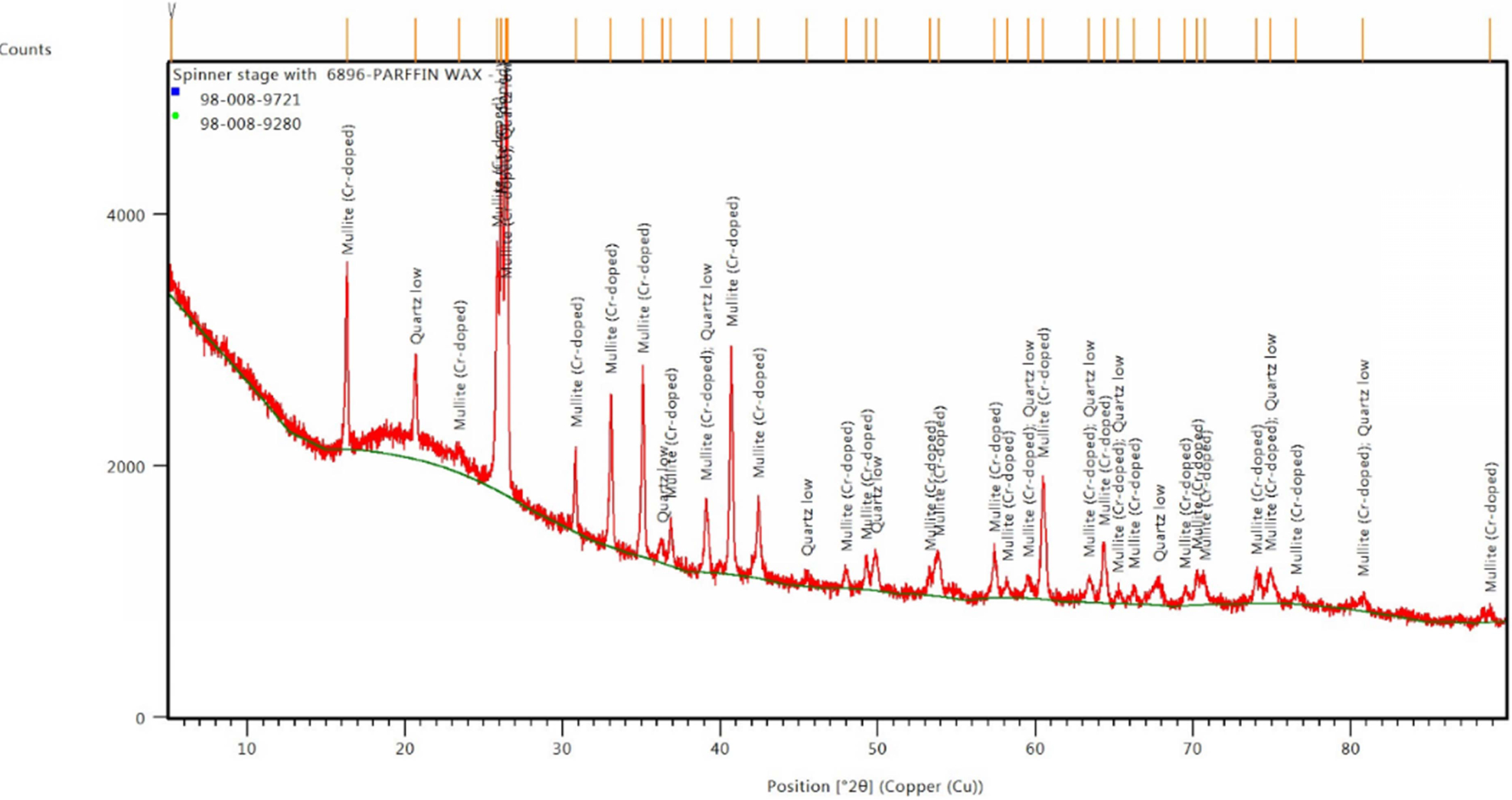
Fig. 9 shows the XRD pattern of as synthesized Ceno PCM. The elements of Ceno PCM along with the 2-theta value is observed from the XRD pattern. Quartz and Mullite are the important phases which are observed in the Ceno PCM from the peaks. JCPDS 46-1045 and JCPDS 15-0776 data evident the presence of Quartz and mullite in the PCM. The amorphous phase is identified in the ranges of 20 to 40-degree 2 theta values in the X-axis. The identification of phase is ensured from the XRD pattern. The crystalline phase of the Ceno PCM definitely useful to improve the property.
Thermal properties of Ceno PCM
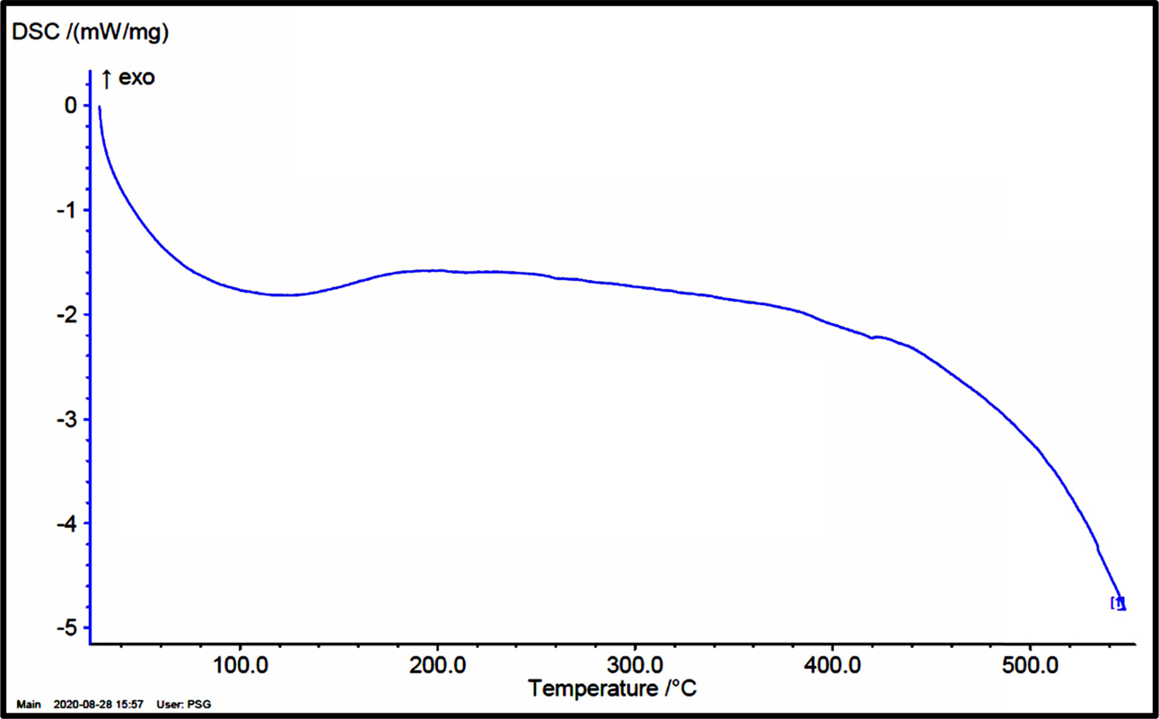
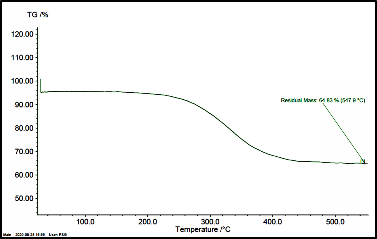
Fig. 10 shows the DSC curve for as synthesized Ceno PCM. This curve was obtained while heating the Ceno PCM powders at 10 oC/min. The major changes at 100 oC and it continues up to 547 oC and the endothermic reactions is evident for the curve. Fig. 11 shows the Thermogravimetric analysis (TGA) for as synthesized Ceno PCM. This curve displays the details of mass loss for the variation of temperature. The increase in tem- perature increases the residual loss. The increase in temperature is due to the change in heat transfer. The residual loss of 64.83% is observed from the curve at the temperature of 547 oC. The changes in peak at 247 oC to 338 oC shows the rate of mass loss of Ceno PCM. The reason for the mass loss is that the degradation of paraffin and evaporation of moisture due to temperature change.
Compressive strength property
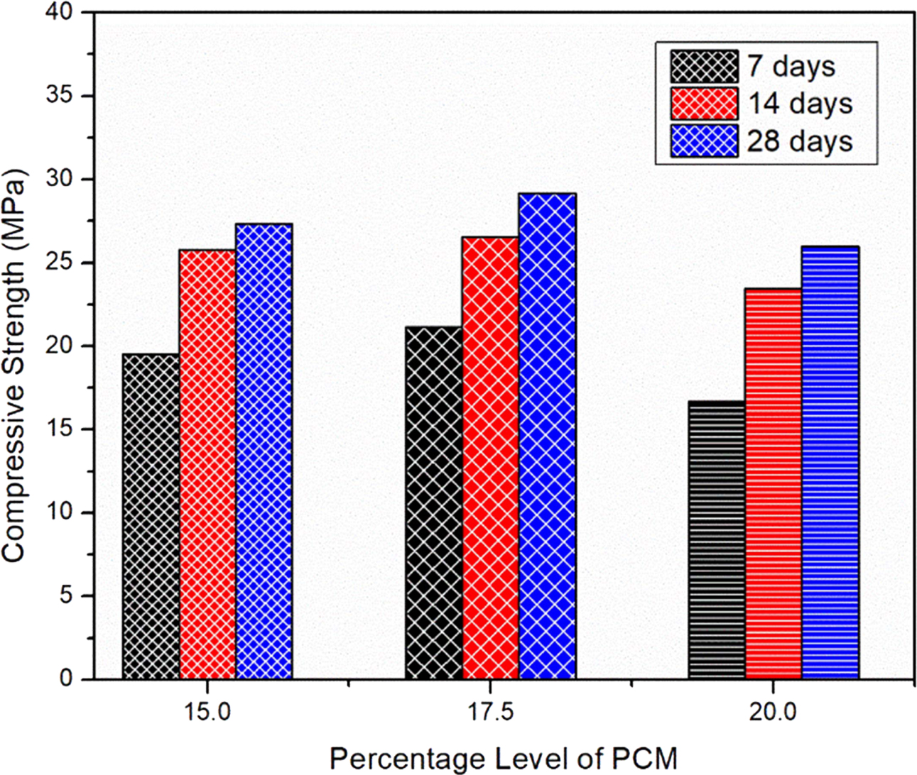
The compressive strength of the casted mortal cube with different percentage of PCM as 15%, 17.5%, 20% is shown in Fig. 12. The high compressive strength is observed for the mortal cube contain 17.5% Ceno-PCM. The increase in percentage of Ceno PCM beyond 17.5% leads to decrease in compressive strength from 21.12 MPa to 16.67 MPa for 7 days of curing. For all the composition of Ceno PCM, the increase in curing time increases the compressive strength of the cube. For the 15% of Ceno PCM, increase in time from 7 days to 28 days increases the compressive strength from 19.51 MPa to 27.33 MPa. Similarly, the improvement in compressive strength is observed for the 17.5% Ceno PCM and 20% Ceno PCM filled cube.
|
Fig. 4 SEM images of Cenosphere (a) 200 μm (b) 20 μm, and (c) Single particle at 20 μm. |
|
Fig. 5 EDS result of Cenosphere. |
|
Fig. 6 Infrared spectroscopy result of Cenosphere. |
|
Fig. 7 FESEM image of PCM in (a) 20 µm, (b) 5 µm, and (c) 2 µm. |
|
Fig. 8 EDX results with spectra peak of PCM composition. |
|
Fig. 9 XRD results of Ceno PCM. |
|
Fig. 10 DSC curve for Ceno PCM. |
|
Fig. 11 Thermogravimetric analysis (TGA) for Ceno PCM. |
|
Fig. 12 Values of compressive strength for the different percentage Ceno PCM Cubes. |
The following conclusions are drawn from the above experimental work,
• The Ceno PCM was produced from paraffin wax and Cenosphere by using Sonication method and the properties of the Ceno PCM was studied by using SEM, EDX, FTIR, TGA and XRD.
• As compared with other materials paraffin PCM was selected due to low cost, availability and eco-friendly in nature. Cenosphere was chosen to encap- sulate the Paraffin without any reduction in strength.
• Thus, the Ceno PCM is prepared with a prescribed proportion and the FESEM & EDX results are good with the combination of Paraffin vs Cenosphere.
• The strength parameters show the best result in the 17.5% of PCM as compared to other percentage levels. And also, if the contribution of Ceno PCM increases, the thermal performance and strength value are decreases after 17.5%.
• Thus, the optimal percentage level was selected to proceed in future works for the further investigations in related to energy efficiency.
- 1. Z. Zhai, M.L.L. Abarr, S.N.J. Al-Saleh, and P. Yate, J. Archit. Eng. 20[4] (2014) 814-824.
-

- 2. S. Chadhurvedi, in Proceedings of the 2008 Architectural Engineering Conference (AEI), September 2008, edited by M. Ettouney (ASCE Press, 2008) p.181.
- 3. T. Ling and C.S. Poon, J. Constr. Build. Mater. 46 (2013) 55-62.
-
- 4. M. Delgado, A. Lázaro, J. Mazo, and B. Zalba, Renew. Sust. Ener. Rev. 16[1] (2012) 253-273
-
- 5. Y. Zhang, G. Zhouz, K. Linz Q. Zhang, and H. Di, J. Build. Environ. 42 (2007) 2197-2209.
-
- 6. N. Zhu, Z. Ma, and S. Wang, J. Energy Convers. Manag. 50 (2009) 3169-3181.
-
- 7. A. Waqas and Z.U. Din, J. Renew. Sust. Energ. Rev. 18 (2013) 607-625.
-
- 8. K. Biswas, J. Lu, P. Soroushian, and S. Shrestha, J. Appl. Ener. 131 (2014) 517-529.
-
- 9. V.V. Tyagi, S.C. Kaushik, S.K. Tyagi, and T. Akiyama, J. Renew. Sust. Ener. Rev. 15 (2011) 1373-1391.
-
- 10. C.Y. Zhao and G.H. Zhang, J. Renew. Sust. Energ. Rev. 15[8] (2011) 3813-3832.
-
- 11. Y. Ozonur, M. Mazman, H.O. Paksoy, and H. Evliya, Int. J. Ener. Res. 30[10] (2006) 741-749.
-
- 12. M.V. Pankova, E.V. Fomenko, N.N. Anshits, T.A. Vershchagina, and A.G. Anshits, J. Chem. Sust. Develop. 18 (2010) 509-516.
- 13. V.V. Tyagi and D. Buddhi, J. Renew. Sust. Energ. Rev. 11 (2007) 1146-66.
-
- 14. L.F. Cabeza, A. Castell, C. Barreneche, A. de Gracia, and A.I. Fernández, J. Renew. Sust. Energ. Rev. 15 (2011) 1675-1695.
-
- 15. K. Kolay and S. Bhusal, J. Fuel 117 (2014) 118-124.
-
- 16. A. Gharsallaoui, G. Roudaut, O. Chambin, A. Voilley, and R. Saurel, J. Food Res. Int. 40[9] (2007) 1107-1121.
-
- 17. T. Khadiran, M.Z. Hussein, Z. Zainal, and R. Rusli, J. Solar Energ. Mater.Solar Cells 143 (2015) 78-98.
-
- 18. C. Voelker, O. Kornadt, and M. Ostry, J. Energ. Build.40[5] (2008) 937-944.
-
- 19. A.F. Regin, S.C. Solanki, and J.S. Saini, J. Renew. Sust. Energ. Rev 12 (2008) 2438-56.
-
- 20. F. Liu, J. Wang, and X. Qian, J. Cem. Concr. Compos. 80 (2017) 317-325.
-
 This Article
-
2021; 22(6): 642-648
Published on Dec 31, 2021
- 10.36410/jcpr.2021.22.6.642
- Received on Apr 29, 2021
- Revised on Aug 4, 2021
- Accepted on Aug 28, 2021
Services
Shared
Correspondence to
- R. Greesan
-
Department of Civil Engineering, MahathAmma Institute of Engineering & Technology, Pudukkottai, 622005, Tamil Nadu, India
Tel : +91- 9894686916 - E-mail: greesan.ram@gmail.com
Clean-Energy Research Institute(CRI), Hanyang University, 222, Wangsimni-ro, Seongdong-gu, Seoul, 04763, Korea
E-mail: jcpr@hanyang.ac.kr