


- Investigation of mechanical and metallurgical behaviour in FSW of AA5052-H32 and AA5083-H111 aluminium alloys
R. Crushana,* and P. Ashoka Varthananb
aAssistant Professor, Department of Mechanical Engineering, St. Joseph College of Engineering, Kanchipuram, Chennai, India - 602117
bProfessor, Department of Mechanical Engineering, Sri Krishna College of Engineering and Technology, Coimbatore, India - 641008This article is an open access article distributed under the terms of the Creative Commons Attribution Non-Commercial License (http://creativecommons.org/licenses/by-nc/4.0) which permits unrestricted non-commercial use, distribution, and reproduction in any medium, provided the original work is properly cited.
The novel approach of the present work is the investigation of mechanical and metallurgical performance characteristics of two aluminium alloy 5052-H32 and 5053-H11 joint welded by friction stir welding. The experimental dissimilar metal friction stir welding investigated the influencing input welding process parameters and resultant effects on the performance characteristics of the welded specimen. The square pin tool with 15 mm tool shoulder diameter and a constant tool feed of 28 mm/min was used with varying tool rotation speed of 800, 1000 and 1200 rpm in conjunction with 10kN axial thrust were utilized in experimentally producing dissimilar weld joints. The welded specimen were subsequently characterized for microstructural, tensile strength and microhardness properties by optical microscopy, scanning electron microscopy, X-ray diffraction analysis, tensile test and Vickers microhardness survey. Improved grain structure and reduced defects and dislocations were observed with specimen welded by 1000rpm tool rotational speed with 87.67% joint efficiency with 13.29% elongation. The influencing parameters was identified to be tool rotational speed contributing significantly in improving microhardness of the specimen by 12.86% over the base aluminium 5083-H32 alloy
Keywords: Friction stir welding, Dissimilar joints, Microstructure analysis, Mechanical behaviour
Different aluminium alloy used in different application, especially 5xxx series termed as marine grade Aluminium alloys are mostly utilized in industrial sectors, including aerospace, marine, automobiles, food industries, etc [1]. Alloys of this series have better weldability and high corrosion resistance when compared to other alloy series. Their spectacular performance is most evident in applications like ship industries due to its combination of high strength and weight reduction [2]. The chief demands in transportation industry are minimization of weight and fuel consumption. These requirements can only be met by lightweight metals such as Aluminium alloys. The aluminium alloys studied in the present work are recently applied in marine and aerospace structures. These applications demonstrate the superior strength to weight ratio performance of aluminium 5052 H32 and 5083 H111 alloys. Aluminium alloy 5052 is more corrosion resistant against general or localized attack when compared to corresponding applications of 4xxx and 6xxx grades that are greatly perceptive to pitting corrosion [3]. This research work considers the strain-hardened alloys AA5052-H32 and AA5083-H111 for the FSW process. The AA5052-H32 aluminium alloy, in addition to very good weldability and cold formability, provides good resistance to corrosion in seawater and hence is abundantly used in marine and industrial atmospheres. The AA5083 aluminium alloy in H111 has better wear resistant properties and better weldability.
Past 30 years many researchers are reported that, compare to other welding process; the FSW process or solid state welding processes are mostly used in aluminium materials. The FSW process is developed by welding institute in 1991 [4]. As mentioned, the FSW joining process can be followed in all the aforesaid applications as it can ensure high-quality joints [5]. FSW process parameters such as tool rotational speed, axial thrust, welding speed and tool geometry and shoulder diameter are the principal influencing factors that determine the strength and performance of any aluminium alloys under friction stir welding. The FSW process parameters are greatly dependable for producing quality weld joints like mechanical and micro structural properties [6-8]. Of these, the significantly studied factors are welding speed, tool geometry, and tool rotational speed and subsequent researchers pursuing effects of axial thrust and varying weld tool passes. [9, 10]. The FSW of dissimilar aluminium alloy make substantial change in mechanical and grain structure changes of FS welded dissimilar AA5052-H32 and AA5083-H111 aluminium alloy [10]. While the FSW process, it is declared that the peak temperature and frictional heat are the leading factors that control grain size of stir zones and commonly the grain size raised with rising speed or speed/feed ratio [10-11]. Further, 5083 Aluminium-magnesium alloys also have their own properties like strain hardness and also have outstanding corrosion resistance [12], weldability, and moderate strength as well. In fact, single or multiple ship hull employ numerous aluminium alloys including 5083, 5383 and 5454 as plate and sheet with needed welded condition [13, 14]. 5083-H111 that readily weldable with all traditional fusion have shown best performance of joint efficiency. Optimum parameter selection assures the dispersion of metals, which will minimizes the crack formation as well. Hence, it is more significant to rectify the defects in FSW joints [15, 16]. A friction stir spot welded lap joint between Silicon carbide and Aluminium-Magnesium alloy was analyzed for influence of aluminium compounds within the friction stirred joint. The welded plates were tensile tested and it was revealed that the strength of the welded invariably depended upon formation of aluminium compounds and aided in bonding of the ceramic com- pound with the magnesium alloy [17]. In an investigation detailing the friction stir spot welding of alumina ceramic and aluminium alloy, the weld joint was characterized by electron microscopy and presence of magnesium com- pounds were found along the weld boundary. Energy dispersive analysis revealed the presence to be magnesium-aluminium compounds and magnesium oxide which were responsible for the weld joint strength between alumina and the aluminium alloy [18]. Aluminium 6063 composite specimens were fabricated with Graphite/Boron carbide/Silicon carbide particulates reinforcements of varying weight percentages and joined by friction stir welding. The weld joint was analyzed to understand the influences of welding parameters and effects of ceramic reinforcements. It was found that the microhard- ness levels and the wear performance of the reinforced specimens were gradually improved with friction stir welding process aiding the dispersion of reinforcement particulates within the weld joint [19]. A new metallization technique was investigated by metallizing Aluminium oxide (Al2O3) ceramic with magnesium foils by friction stir spot welding process. The metallized ceramic plate was tensile tested and was found that the tensile strength between the ceramic and magnesium alloy foil was drastically improved due to the formation of micro- crystalline aluminium-magnesium oxide layer at the weld interface [20]. However, in most of the literature works, the researchers have made separate investigation of aluminium alloys 5083 and 5052. Still, the study about the friction stir weldability of 5052-H32 and 5083- H111 alloys hasn’t yet found.
The novel approach of the present work involves the experimental evaluation of the influence of input para- meters of friction stir welding of two aluminium alloys 5052-H32 and 5083-H111 and subsequent investigation of the welded specimen for metallurgical and mechanical characteristics such as microstructure, chemical com- position post welding, tensile strength and specimen microhardness.
Aluminium alloys 5052-H32 and 5083-H111 are high performance grades of aluminium alloys in their re- spective temper grades showing superior performance attribute such as high weldability and strain hardening. Aluminium alloy 5052-H32 possesses enhanced corrosion resistance and goof cold-formability aptitude while 5083-H111 exhibits better wear resistance. A dissimilar joint among these alloys by a suitable technique is bound to enhance these properties forming a superior weld joint with an amalgam of properties of these respective base alloys. Table 1 summarizes the base metals' chemical composition identified by spectro- chemical analysis.
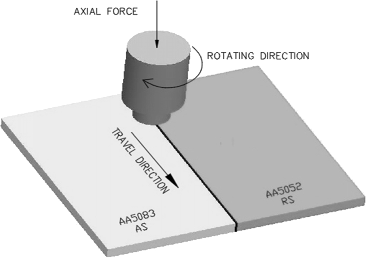
This research work considers the strain-hardened alloys AA5052-H32 and AA5083-H111 (quarter hard), 5 mm plates as base metals, and was FS welded by a well designed FSW machine. It employs square type tools with M2, high-speed steel, quenched at 1020oC, and categorized by a 50~55 HRC. The profile of the tool was square shaped with shoulder diameter of 15 mm and 4.7 mm tool height. The square pin profile was selected to provide good amount of material mixing at the nugget zone providing better microhardness [4]. The schematic representation of the experimental FSW process of the present work can be inferred from Fig. 1. The process parameters for the FS welding were set as follows: trail 1: 800 rpm (TRS), 28 mm/min (WTS) and 10 kN (AL), trail 2: 1000 rpm (TRS), 28 mm/min (WTS) and 10kN (AL) and trail 3: 1200 rpm (TRS), 28 mm/min (WTS) and 10 kN (AL). AA5052-H32 retreating side (RS) and AA5083-H111 advancing side (AS). Table 2 enumerates the process parameters of the FS welding.
The process parameters for the FSW process were studied from the literature survey. The parameters such as welding speed, tool rotational speed, tool geometry, tool diameter, axial thrust were some of the principal factors that have been identified as major factors of a FSW process [1, 11]. These factors were the focus point of research in studies that analyzed their influence in the welding process and the resultant weld joint charac- teristics [2]. Among these parameters, tool rotational speed, tool feed and axial thrust particularly influence the grain structure of the weld joint of light density alloys such as aluminium and magnesium alloys [6]. Thus the present study involved the analysis of behavior weld joint with four input parameters such as square tool shoulder diameter, tool rotational speed, tool feed and axial thrust. Among these parameters, the tool rotational speed was varied in the present study to analyze its effects on the resulting weld joint.
The weld specimen microstructural and mechanical characterization is performed using optical microscopy (OM) analysis, XRD and SEM analysis, and tensile test and microhardness survey. The standard experimental process is followed to find the micro structural and mechanical characterization of AA5052-H32 and AA5083-H111 FS welded joints. Wire-Cut EDM process followed to cut the specimens for metallurgical and mechanical testing from AA5052-H32 and AA5083-H111 FS welded plates. The optical and scanning electron microstructure characterizations are utilized to identify if any defects were present in AA5052-H32 and AA5083-H111 FS welded joints. ASTM E293-11 standard was adopted for metallurgical characterization. Further, the specimens` cross sections were polished by the alumina suspensions, fixed with Keller’s reagent (10 sec) to observe its microstructure. The tensile specimens and the configuration are arranged as per the ASTM-E8M standard. Prior to the tensile strength analysis, the measurement of microhardness (Vickers tester) under the load of 1 Kgf is done for 15s with centrelines of the tensile specimen’s cross section with the aid of automated microhardness tester. The ASTM E384-11e1 standard is adopted for Vicker's microhardness test. The thickness of samples is 5 mm.
|
Fig. 1 Schematic representation of FSW process. |
|
Table 1 Chemical composition of base aluminium alloy (AA5052-H32 and AA5083-H111) |

Metallurgical Characterization
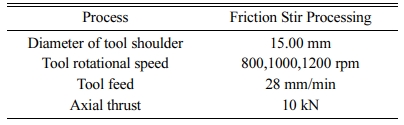
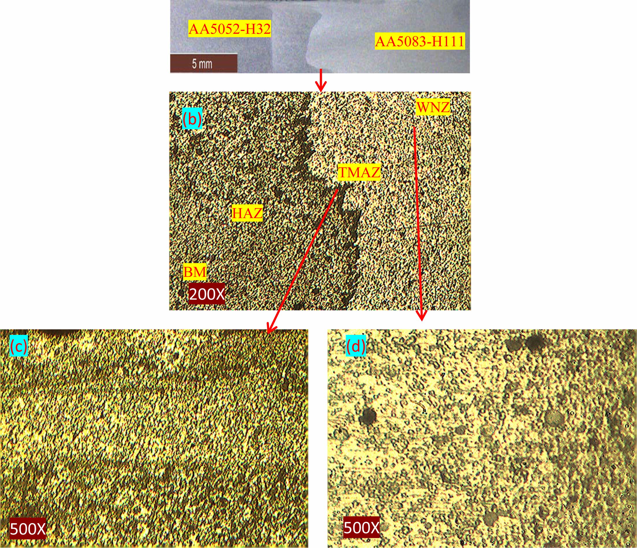
The transverse plane macrostructure images of dissimilar FSW samples prepared with varying tool rotational speeds are shown in Fig. 2(a), 3(a) and 4(a). When FSW is performed with 800 rpm tool rotational speed, the pin-hole defect is formed due to poor interaction as observed in the bottom of the welded specimen. This defect is the cause of weak bonding at the weld nugget. The optical microstructure of the base metal aluminium alloys 5052-H32 and 5083-H111 can be observed from Fig. 2(b) and 2(c) respectively. The grain sizes of the base metals are not uniform. It is observed that due to the high magnesium content, the non-equiaxed large grains of aluminium 5083 H111 alloy are seen dark when compared to 5052 H32 alloy. The microstructure of FS welded at 800, 1000 and 1200 rpm and 28 mm/min welding speed can be observed from Fig. 2(d), 3(b) and 4(b). The recrystallized zone is termed as nugget zone and in Aluminium alloys; it normally includes fine grain size material. While welding, the grain structure of base metal gets eradicated and also produce the fine grain structure in friction stir welded zone [8]. In the present experiment, larger constituent particles are observed in the stir zone, when the TRS is fixed to 1000 rpm. In FSW, variations in weld nugget are observed due to dynamic recrystallization process. Fig. 2(d) shows only the coarse grains at rotational speed of 800 rpm & tool feed of 28 mm/min. Fig. 2(e) shows the thermo mechanically affected zone at magnification factor of 500 where the grain distri- bution is non-homogenous containing coarse and fine grains blended together. The coarse grain structures suffer severe dissolution due to the high heat produced during the FSW process thereby significantly increasing the chances of dislocations.
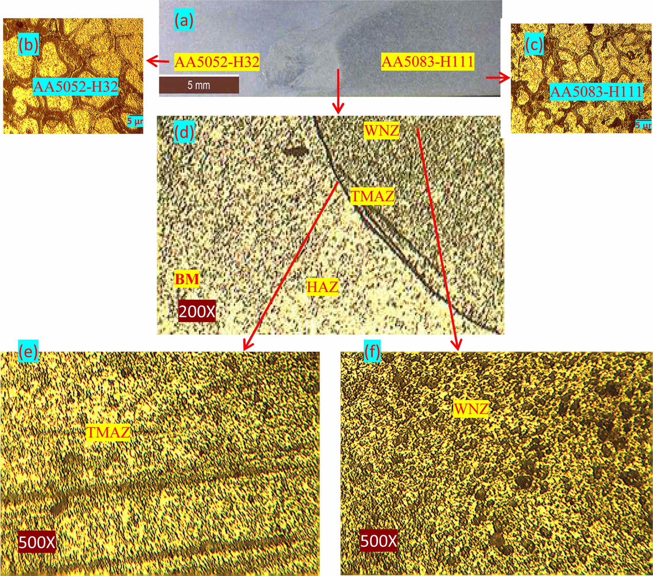
Fig. 3(b) shows the fine grains at rotational speed 1000 rpm & 28 mm/min, which has improved than the previous weld. The presence of fine grains in the thermo mechanically affected zone and the weld nugget zone can be inferred from Fig. 3(c) and 3(d). The refined grain structure in the weld nugget zone and the thermo mechanically affected zone are resultant of the high heat generated due to increased TRS of 1000 rpm at the same tool feed of 28 mm/min. The plastic deformation has resulted in dynamic recrystallization in the nugget zone thereby produced finer grains as seen in Fig. 3(c).
Fig. 4(b) illustrates large grains packed thickly alongside finer grains in the weld nugget zone of the welded specimen. This specimen was friction stir welded at 1200 rpm & tool feed 28mm/min. The presence of larger grains is due to the higher heat rate generated as a result of high TRS [4]. Fig. 4(c) and 4(d) respectively illustrate the thermo mechanically affected and weld nugget zones of the specimen. As observed the presence of larger grains alongside finer grains lead to coarsened microstructure within these regions leading to reduction of strengthening effect in the weld joint. This is directly influenced by the high heat and subsequent dislocations produced in the solidification of the weld joint. The defect-free weld is produced when the input parameters are 1000 rpm of tool rotational speed & 28 mm/min of tool feed. At FSW, due to the frictional heat input and severe plastic deformation, the breaking up of original microstructure has been observed. Further, the transition zone is also observed from Fig. 2(d), 3(b) and 4(b) for varied tool rotational speeds.
With 800 rpm & 1200 rpm, improper stirring effect and non optimal heat input has caused the thickness of oxide layer to increase gradually. As the rotational speed increases, the oxide layer insoluble has initiated the particle diffusion by proper stirring effect. With the inclusion of oxide layer at broken particles (dark), the fracture initiation at the root along zigzag line is observed [4], which causes failure from the weld nugget. Still, it is evident that higher rotational speed formation of oxide layer endures the increase of transition zone strength. The observation is also proved by [9], where the authors state that at low rotary speeds or high welding speeds, inadequate stirring of dissimilar metal could direct limited contravention of the expected Al2O3 oxide layer. Similarly, the low heat input of FS welding process also limited ability of plastic materials. as a result, there occurs broken oxide particle formation in dark crimped criss-cross line or defects in kissing bond. However appropriate suitable selection of FSW process parameters will eliminate or reduce the formation of zigzag lines which directly contributes in improving mechanical performance [7, 9]. With 1000 and 1200 rpm tool rotational speed, the welding is complete, without any visible defects. Very minimal mixing between both alloys can be seen throughout the stir zone for the specimens. Efficient inter mixing is achieved between the alloys, when the tool rotational speed becomes at 1000 rpm.
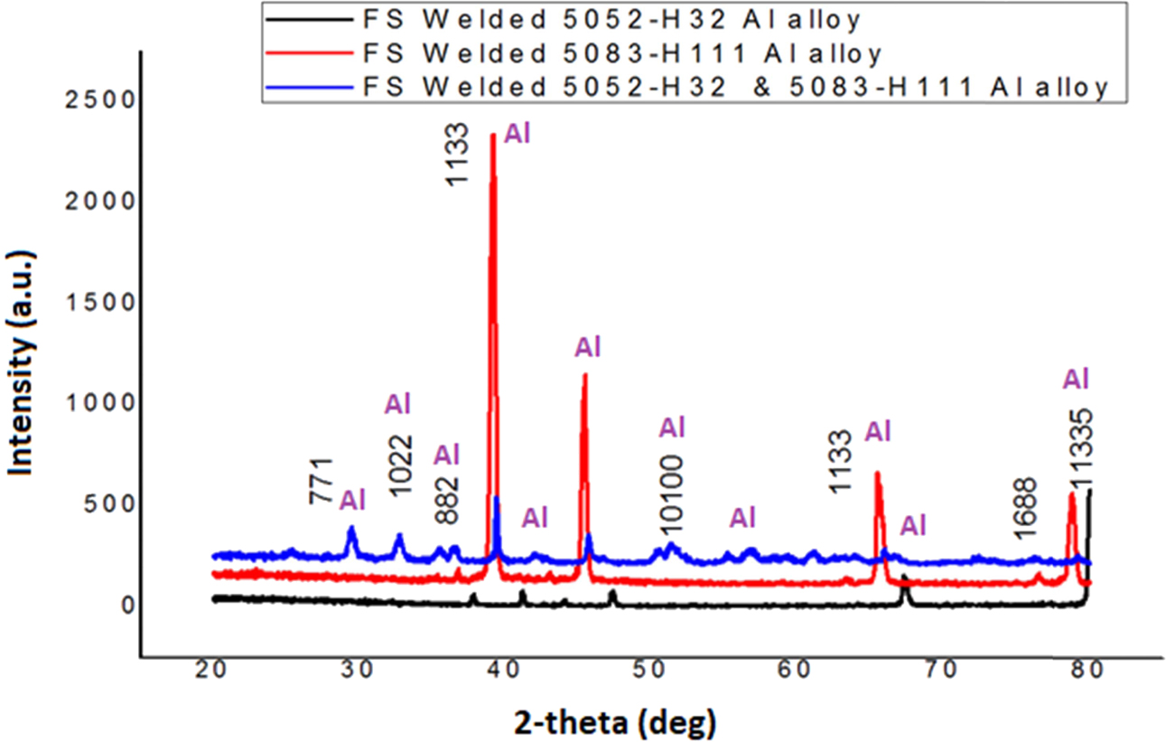
Furthermore, FSW contributes to strengthening of the precipitation as evidenced by the XRD analysis results in Fig. 5, where the intensity of AA5083-H111 alloy peaks, which is then seen to be evenly distributed for the FS welded dissimilar alloy. This is due to the fact that in the WZ due to the effect of FSW, the grain size decreases and becomes finer in the stir zone leading to equiaxial grain distribution.
Evaluation of mechanical properties
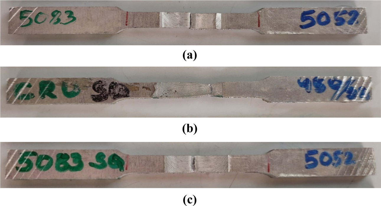
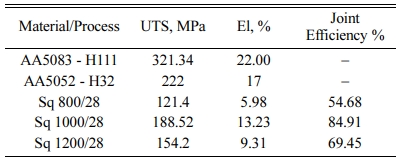
Table 3 enumerates the tensile strength (MPa) of base aluminium alloy AA5083-H111 and AA5052-H32. The AA5083-H111and AA5052-H32Aluminium alloy butt welds for different rotational speed: 800, 1000 and 1200 rpm and 28 mm/min are identified. Fig. 6 illustrates the fracture of the tensile test samples of the FSW joints at various tool rotation speed process parameters.
The TRS (rpm) increased from 800 rpm to 1200 rpm, the tensile strength values also increases with high values [11]. In general, the tensile strength of weld nugget will be less than that of base material, and similar results have also been identified from this experiment. Among the three welded joints, 1000 rpm gives best tensile strength of 188.52 MPa with the joint efficiency of 84.91% of the weaker base metal (AA5052-H32) and other joints are 121.4 MPa and 154.2 MPa respectively.
Fig. 6 shows the specimens' brittle failure at the weld centre in: sample (a), which is due to the low rotational speed. Thereby it occurs at low tensile strength and in the microstructure transition zone noticed kissing bond defect [13]. While analysing sample (b), shows ductile failure due to the perfect speed, which also results in maximum tensile strength and elongation, and due the plastic deformation, the weld nugget is seen with very fine equipped grains. Sample (c) the specimen shows semi ductile fracture fails nearby the weld centre, which is also occurred due to the low frictional heat supply and results with low elongation as well. It has been recognized that in FSW operations, the frictional heat generation is the significant factor, and the ultimate microstructure in the FS welded zone is greatly inclined by this phenomenon [12].
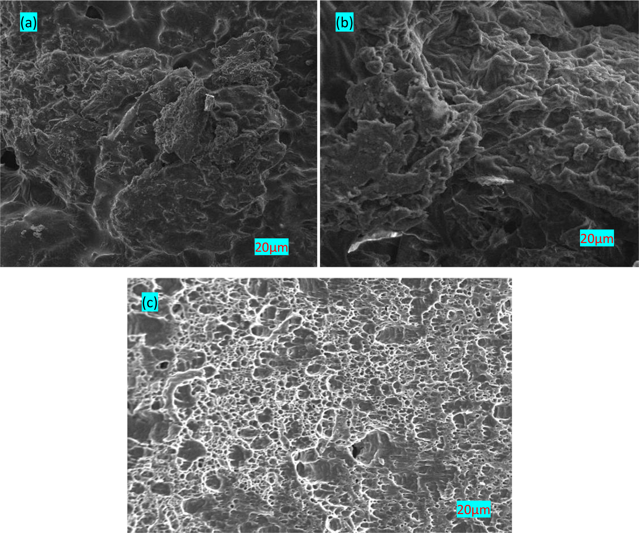
Fig. 7(a-c) illustrates the fracture surface of the UTS specimen of 1000 rpm & 28 mm/min. The extensive plastic deformation has occurred in tensile test even with fracture surface examined at 800 rpm (Fig. 7(a)). It can be seen that the effect of FSW has made the fine grain distribution possible in the weld zone of the specimen thereby leading to finer grain structure formation and distribution (Fig. 7(b)). Similarly, it also shows the dimple characterizing particularly dimple patterns with different size. Due to the elongation, there exists cavities shiny boundary as well. The fracture morphology of the FSW specimen under 1200 rpm process parameter condition can be observed in Fig. 7 (c) where the formation of dimples likely due to the influence of high TRS of 1200 rpm which leads to the failure of the FS welded dissimilar joints.
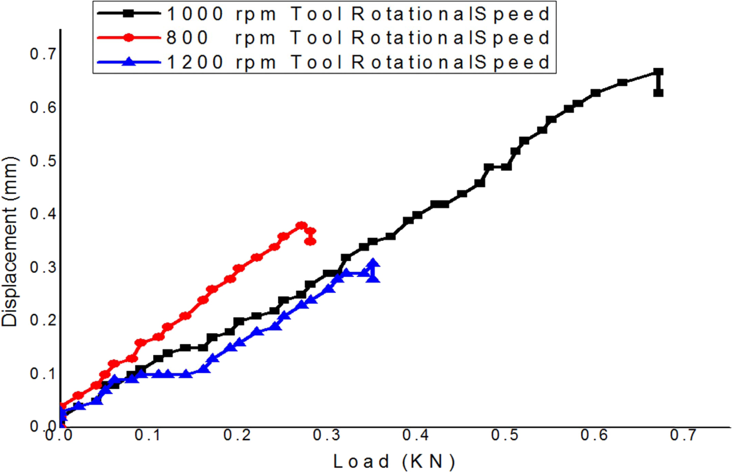
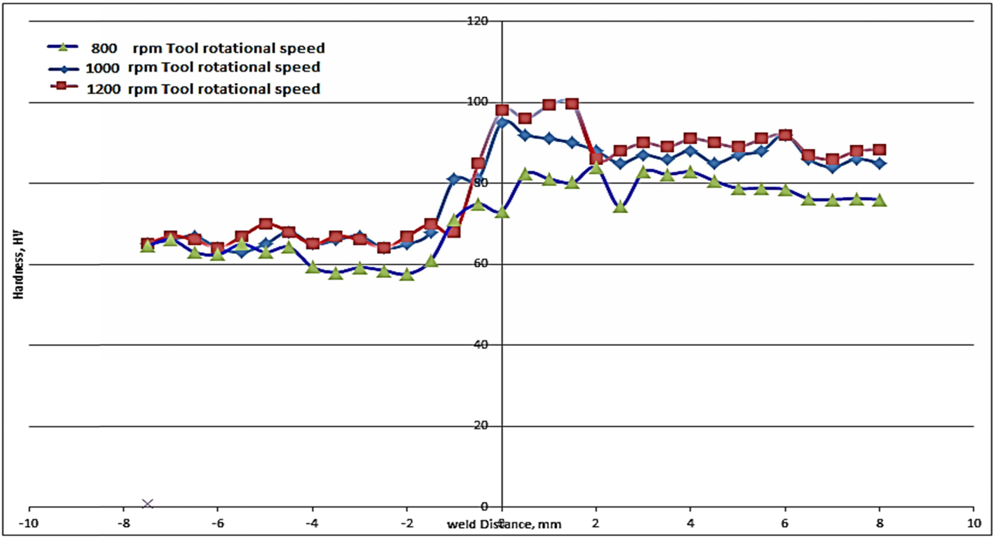
Fig. 8 illustrates the Load vs. Displacement relation- ship observed during the experimental procedures of the FSW dissimilar Aluminium alloys. At 1000 rpm tool rotation speed, the tensile properties are increased due to the reduction in agglomerations compared to 800 rpm and 1200 rpm tool rotation speeds. Fig. 9 shows the microhardness analyses of FS welded dissimilar aluminium alloy AA5083-H11 and AA5052-H32. It is observed that AA5083-H111 alloy kept in the advancing side has 85HV1 of microhardness values of the base metal.
The microhardness of AA5052-H32 alloy is around 65 HV at retreating side of FS welded process. Highest values of microhardness: 83.9, 90 and 99.7 HV1 are observed at the weld nugget samples of A, B and C respectively. Influence of FS welded specimen micro- hardness depends on grain size, dislocation density, distribution of intermetallic components [13]. The nugget zone’s microhardness is observed to be higher for 800 rpm & 1000 rpm samples due to the recrystallized grain size, which is clearly demonstrated in microstructure studies which is also in accordance to the Hall-Patch equation.
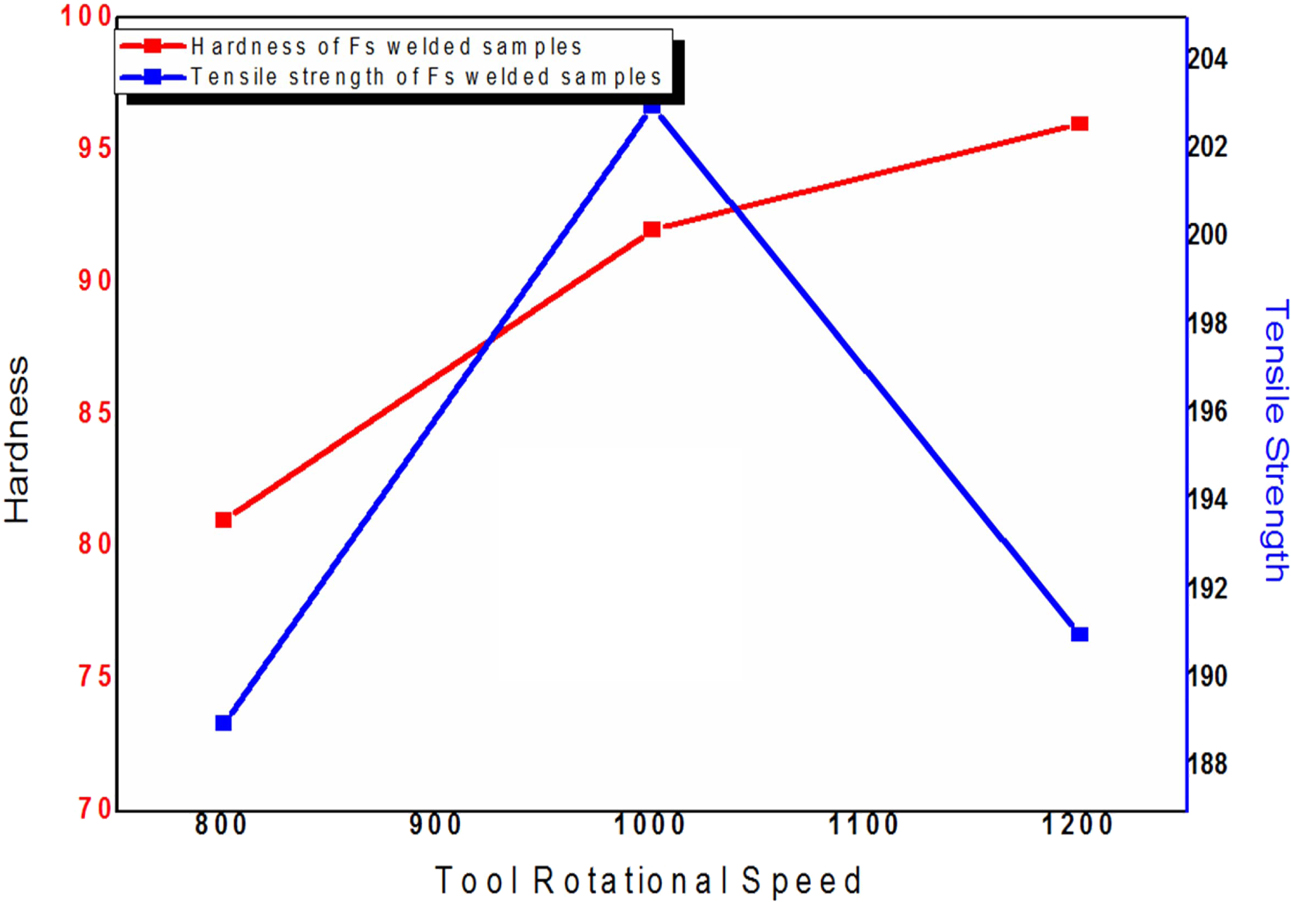
The dislocation density of microhardness profile gets affected due to the strain hardening base metals. The reached peak value of stir zone is 99.7 HV, and it is due to the dynamic crystallization of nugget zone. The existence of increasing microhardness of base metal in the stir zone also makes continues increasing of micro- hardness value in AS side as well. Maximum micro- hardness occurs due to low heat rate with 1000 rpm welded specimen. The maximum rotation speed causes annealing action in stir zone strain hardened materials joining [5]. In FSW with more plastic deformation, a strain is observed in advancing side than the retreating side, and it results with high heat generation nearer to the weld centre. This causes non uniform plastic flow, thereby had a significant result on microhardness distribution deviation of the stir zone on both sides. This finding is further bolstered by the relationship between FS welded Dissimilar aluminium alloy Tensile strength and Microhardness as inferred from Fig. 10, where the peak tensile strength at 1000 rpm coincides with the microhardness value of 90 HV1, which is better than microhardness obtained at 800rpm but lower than 1200 rpm, although the tensile strength decreases as the tool rotation speed increases beyond 1000 rom. Thus the optimum tool rotation speed can be found as 1000 rpm with corresponding improved microhardness value of 90 HV1.
|
Fig. 2 FS welded AA5052-H32 and AA5083-H111 specimen under 800 rpm tool rotational speed (a) Macrograph; (b) Microstructure of
base aluminium 5052-H32 alloy; (c) Microstructure of base aluminium 5083-H111 alloy; (d) Micrograph of FS welded specimen joint; (e)
Magnified micrograph showing thermo mechanically affected zone; (f) Micrograph of weld nugget zone. |
|
Fig. 3 FS welded AA5052-H32 and AA5083-H111 specimen under 1000rpm tool rotational speed (a) Weld surface macrograph; (b) Micrograph of FS welded specimen joint; (c) Magnified micrograph showing thermo mechanically affected zone; (d) Micrograph of weld nugget zone. |
|
Fig. 4 FS welded AA5052-H32 and AA5083-H111 specimen under 1200rpm tool rotational speed (a) Weld surface macrograph; (b) Micrograph of FS welded specimen joint; (c) Magnified micrograph showing thermo mechanically affected zone; (d) Micrograph of weld nugget zone. |
|
Fig. 5 XRD analyses of FS welded base AA5052-H32, AA5083- H111 and FSW dissimilar AA5052-H32- AA5083-H111 |
|
Fig. 6 Tensile test sample: (a) Fracture tensile samples of FSW joint -800 rpm (b) Fracture tensile samples of FSW joint -1000 rpm (c) Fracture tensile samples of FSW joint at 1200 rpm. |
|
Fig. 7 SEM analysis of FSW process parameter of (a) 800 rpm, 28 mm/min (b) 1000 rpm, 28 mm/min and 1200 rpm, 28 mm/min of dissimilar 5052-H32, 5083-H111 Al alloy. |
|
Fig. 8 Load vs. Displacement relationship. |
|
Fig. 9 Microhardness survey of FS welded joint. |
|
Fig. 10 Microhardness and tensile strength analysis. |
The present work is the investigation of a novel friction stir welded two dissimilar aluminium alloy 5052-H32 and 5083-H111 joint. The experimental investigation was performed to identify the influencing input process parameter and subsequent effect on the mechanical and metallurgical characteristics of the welded joint. The results of the study are:
• The two aluminium alloys 5052-H32 and 5083-H111 were friction stir welded successfully. The experi- mental weld joints were prepared under varying tool rotational speeds of 800, 100, 1200 rpm and constant tool feed of 28 mm/min and axial thrust of 10 kN.
• The experimental weld specimens were characterised for mechanical performance by tensile test and Vickers microhardness survey. The weld specimen exhibited peak tensile strength of 188.52 MPa was joined with the input tool rotational speed of 1000 rpm. The micro- hardness value observed for this specimen was 90 HV which was higher than the one observed under 800 rpm tool rotational speed condition but lower than 1200 rpm condition.
• The microstructure of the welded specimens revealed better alloy material mixture in the nugget with increasing tool rotational speed which exhibited good weld geometry and ductile fracture when compared to the brittle fracture observed when the input tool rotational speed was 800 rpm. This is the resultant of lack of heat produced in the nugget zone and appearance of ‘kissing bond’ defect.
• The specimen welded under 1000 rpm tool rotational speed exhibited comparatively better microstructure with finer grain structure distribution, better coale- scence among the constituent alloys producing higher tensile strength and better ductile fracture performance.
• The average microhardness in the weld nugget zone was better for weld specimens with increased tool rotational speeds with specimen welded under 1200 rpm exhibiting peak microhardness of 99.7 HV, while the specimen welded with 1000 rpm exhibited 90 HV. This is due to the softening of materials in the nugget during high heat production on increasing stirring speed.
• The overall performance of the welded specimens were compared and found that the specimen FS welded under 1000rpm tool rotational speed, 28 mm/min tool feed was found to exhibit better microstructural and mechanical characteristics.
- 1. R. Pandiyarajan, P. Maran, S. Marimuthu, and K. C. Ganesh, J. Mech. Sci. Tech. 31 (2017) 4711-4717.
-

- 2. G. Cam and G. Ipekoglu, Inter. J. Adv. Manu. Tech. 91 (2017) 1851-1866.
-
- 3. R. Pandiyarajan, P. Maran, S. Marimuthu,and K. Arumugam, Mater. Tod. Proc. 19 (2019) 256-259.
-
- 4. M. Bodaghi and K. Dehghani, Inter. J. Adv. Manu. Tech. 88 (2017) 2651-2660.
-
- 5. H.M.Z. Jamalian, M. Farahani, M.K.B. Givi, and M. Aghaei, Inter. J. Adv. Manu. Tech. 83 (2016) 611-621.
-
- 6. H. Bisadi, M. Tour, and A. Tavakoli, Ame. J. Mater. Sci. 1 (2011) 93-97.
-
- 7. S. Shanavas and E.R.J. Dhas, IOP Conference Series: Mater. Sci. and Eng. 247 (2017) 012016.
-
- 8. Y. Yong, Z. Da-tong, Q. Cheng, and Z. Wen, Trans. Nonfer. Meter. Soc. Chi. 20 (2010) 619-623.
- 9. H. Zhen-Bo, P. Yong-Yi, Y. Zhi-Min, and L. Xue-Feng, Trans. Nonfer. Meter. Soc. Chi. 21 (2011) 1685-1691.
- 10. R. Pandiyarajan, P. Maran, S. Marimuthu, K. Arumugam, and M.P. Prabakaran, Adv. Mater. Proc. Tech. In press (2020) 1-9.
-
- 11. K. Lakshminarayanan, V. Balasubramaniyan, and K. Elangovan, Inter. J. Adv. Manu. Tech. 40 (2009) 286-296.
- 12. P. Kah, R. Rajan, J. Martikainen, and R. Suoranta, Inter. J. Mech. and Mater. Eng. 10 (2015) 26.
-
- 13. R. Moshwan, F. Yusof, M.A. Hassan, and S.M. Rahmat, Mater. Des. 66 (2014) 118-128.
-
- 14. H.J. Aval, S. Serajzadeh, and A.H. Kokabi, Inter. J. Adv. Manu. Tech. 52 (2011) 531-544.
-
- 15. W.Y. Li, T. Fu, L. Hütsch, J. Hilgert, F.F. Wang, J.F. dos Santos, and N. Huber, Mater. Des. 64 (2014) 714-720.
-
- 16. J.C. Park, and S.J. Kim, Rar. Met. 30 (2011) 628-632.
-
- 17. H. Sonomura, T. Ozaki, K. Katagiri, Y. Hasegawa, T. Tanaka, and A. Kakitsuji, Ceram. Int. 46[6] 2020 7654-7658.
-
- 18. H. Sonomura, T. Ozaki, K. Katagiri, Y. Hasegawa, and T. Tanaka, J. Ceram. Soc. JAPAN. 127[2] 2019 127-130.
-
- 19. B. Suresh Babu, G. Chandramohan, C. Boopathi, T. Pridhar, and R. Srinivasan, J. Ceram. Process. Res. 19[1] 2018 69-74.
- 20. H. Sonomura, T. Ozaki, K. Katagiri, Y. Hasegawa, T. Tanaka, and A. Kakitsuji, Ceram. Int. 47[9] 2021 12789-12794.
-
 This Article
-
2021; 22(6): 620-628
Published on Dec 31, 2021
- 10.36410/jcpr.2021.22.6.620
- Received on Mar 15, 2021
- Revised on Aug 2, 2021
- Accepted on Aug 28, 2021
Services
Shared
Correspondence to
- R. Crushan
-
Assistant Professor, Department of Mechanical Engineering, St. Joseph College of Engineering, Kanchipuram, Chennai, India - 602117
Tel : +91-790-433-9337 - E-mail: crushanlinu@gmail.com
Clean-Energy Research Institute(CRI), Hanyang University, 222, Wangsimni-ro, Seongdong-gu, Seoul, 04763, Korea
E-mail: jcpr@hanyang.ac.kr