


- Na2CO3 effect on high-strength lightweight ceramsite prepared from demagnesium boron mud and oil shale semi-coke
T. Chena, L. Lianga,*, B. Dia and G. Gianb
aDepartment of Environmental Engineering, School of Resource and Civil Engineering, Northeastern University, Shenyang 110000
bDepartment of Civil and Environmental Engineering, Faculty of Science and Technology, University of Macau, Macau, 999078 ChinaThis article is an open access article distributed under the terms of the Creative Commons Attribution Non-Commercial License (http://creativecommons.org/licenses/by-nc/4.0) which permits unrestricted non-commercial use, distribution, and reproduction in any medium, provided the original work is properly cited.
High-strength ceramsite was prepared by using demagnesium boron mud and oil shale (OS) semi-coke as the main raw materials, Na2SiO3 as binder, and Na2CO3 as foaming agent. In the ceramsite with a 1:1 ratio of demagnesium boron mud and OS semi-coke, 3% Na2SiO3, and 10% Na2CO3 sintered at 1070 oC, the porosity, apparent density, and compressive strength reached 22.63%, 1398.33 kg/m3 and 11.50 MPa, respectively. Na2CO3 played a decisive role in the sintering of high-strength ceramsite. Thermogravimetric analysis and X-ray diffraction results showed that the gas produced by raw meal during the heating process reduced the apparent density of ceramsite, and that new minerals such as albite and forsterite were produced during the firing process. The forsterite formed islands within an albite framework, thereby strengthening the ceramsite
Keywords: Demagnesium boron mud, ceramsite, apparent density, porosity, compressive strength
As the residue of borax and boric acid production from willemite or magnesite, China's boron mud is mainly composed of MgO and SiO2, with minor Fe2O3, B2O3, CaO and Al2O3 [1]. The borax industry discharges a huge amount of boron mud (typically 4-5 tons per ton of borax production). Over 800 thousand tons of boron mud have been generated per year and more than 10 million tons have accumulated in China [2]. With its high alkali content and fine particles, stacked boron mud causes serious pollution of air, soil, and ground water. In recent years, some efforts have been made to extract the valuable elements like silicon and magnesium from boron mud, prepare boron magnesium fertilizer, soil conditioner or functional building materials [2-5]. However, after silicon and magnesium removal, large volumes of waste residues remain. The production of boron-magnesium fertilizer is relatively low, and cannot consume the huge amount of boron mud produced by ludwigite. Therefore, the resource utilization of high-value components in bulk boron mud is urgently demanded.
Oil Shale (OS) is regarded as a potential supplement and substitute of fossil fuels [6]. However, the environ- mental impacts of OS semi-coke produced from the oil shale retorting process have gradually raised concern. OS semi-coke reportedly leaches more heavy metals (Cr, Mn, Co, V, Zn, and Cu) than natural OS [7-9]. Such large quantities of OS semi-coke can hinder the development of the OS industry unless properly managed [10]. The utilizations of OS semi-coke in com- bustion [11], solid adsorbents, carbon-based adsorbents, geopolymers, ingredients of construction materials, and others have been well studied [12, 13]. However, as the existing technologies are immature, they are not widely used in practice. More economical and environmentally friendly methods for OS semi-coke disposal are required.
Proper disposal of these solid wastes is an urgent environmental problem. In particular, the solid waste must be converted to a valuable secondary product [14]. Mineral wastes that cannot easily be reused as raw materials are increasingly being converted to new artificial aggregates [15-17]. Artificial aggregate can also solidify contaminants, greatly reducing the leaching of heavy metal ions and providing new ideas for the resource utilization of tailings [18]. Traditional light weight aggregates (LWA) are usually formed from natural raw materials such as clay and shale. Demagnesium boron mud is a mineral waste with a clay-like elemental composition [19]. Therefore, a new type of ceramsites might be formed from demagnesium boron mud as a substitute of clay minerals. Another raw material is OS waste residue, which is widely used in firing ceramsites [20, 21]. The main components of this residue (SiO2 and Al2O3) are good candidates for ceramsite formation [22]. Unfortunately, the commonly used artificial ceramsites are low-strength, high-density materials unsuitable for preparing high-performance concrete. This study is the first attempt to prepare a new aggregate product with higher strength and lower weight than the current artificial lightweight aggregates from boron mud and OS semi-coke, which can not only solve the huge environmental risk caused by large-scale storage, but also realize the high-value resource utilization of the two kinds of solid wastes. Moreover, the study also provide an imageJ grayscale analysis method to explore the pore change law during the ceramsite firing process, and it can also provide a certain reference for the related research of ceramsite.
Materials
Demagnesium boron mud
Boron mud was taken from boron mud storage yard in Kuandian County, Liaoning Province, China. Demagnesium boron mud was obtained by acid leaching from boron mud. A 4:1 mixture of 50% sulfuric acid and boron mud was used and heated at 70 oC for 120 min to remove magnesium from boron mud. The acid-leaching boron mud was then washed with distilled water to pH 6. After being dried to constant weight, demagnesium boron mud was passed through a 300-mesh sieve, and taken the lower part of the sieve as a spare.
OS semi-coke
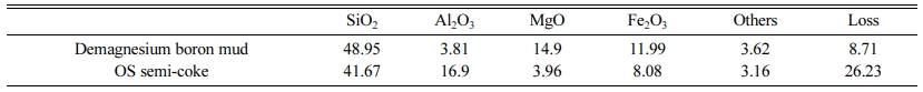
OS semi-coke was taken from the dry distillation waste slag dump of Fushun Open-pit Mine, Liaoning Province, China. OS semi-coke was crushed with a crusher and filtered through a 50-mesh sieve. Then the sieves were put into the ball mill for ball milling to below 300 meshes as a spare. The main elements of demagnesium boron mud and OS semi-coke are shown in Table 1.
Preparation of LWA
Demagnesium boron mud and OS semi-coke were mixed in the ratio of 1:1. A certain amount of foaming agent Na2CO3, 3 g Na2SiO3 and an appropriate amount of water were added to every 100 g of the mixture.
The mixture was compacted into a cylinder with a diameter of 25 mm and a height of 10 mm by a mold, and then dried at 120 oC for 2 h to obtain the green bodies. The prepared green bodies were then fired in a furnace with high temperature resistance. In the furnace, after heated from room temperature to 500 oC at 10 oC/min, the green bodies were preheated at 500 oC for 10 min, and then heated at 15 oC/min to 900 ~ 1100 oC. After holding at the target temperature for 20 min, the power supply was stopped and the samples were cooled naturally to room temperature in the furnace.
Analysis method
The porosity measurement method was adopted by imageJ grey analysis method. The specific method is as follows. The ceramsites was cut from the center, and the cross section of the ceramsite was polished and coated with thick aluminum powder. After flattening the powder with a knife, the surface was imaged with a digital camera and analyzed with ImageJ software to observe the internal pore morphology and calculate the porosity. The compressive strength of ceramsites was measured by the maximum pressure withstood by the ceramsites under the crushing strength machine (Instron Corporation 34SC-5, America). The density of the ceramsite was measured by the Archimedes method. The water absorption of ceramsite was recorded by the rate of weight change before and after the ceramsite was soaked for 30 min. The thermal behavior of the raw materials was studied by using a thermogravimetric analyzer (NETZSCH-Gerätebau GmbH DSC404F3, Germany). The test conditions were set as follows. In an air atmosphere, the sample was heated from room temperature at a rate of 10 oC/min, and the end tem- perature is 1200 oC. The properties of both raw materials and the sintered products were characterized by X-ray diffraction spectroscopy (XRD) (PANalytical B.V. X Pertpro, Netherlands) and scanning electron microscopy (SEM) (Carl Zeiss AG ULTRA PLUS, Germany).
|
Table 1 Raw materials of demagnesium boron mud and OS semi-coke (wt%), determined by X-ray fluorescence analysis |
Effect of Na2CO3 on the physical characteristics of LWA
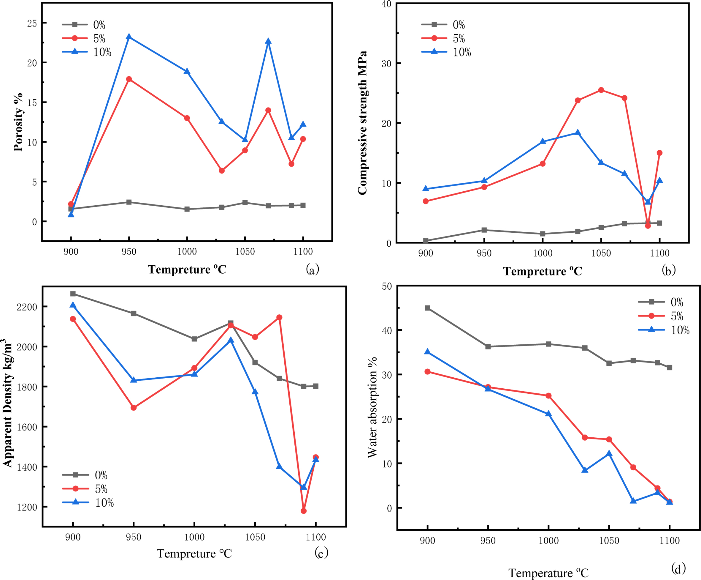
The porosities, compressive strengths, apparent densities, and water absorptions of the ceramsite with different Na2CO3 contents are presented in Fig. 1.
As shown in Fig. 1(a), When there was no foaming agent in green bodies, the porosities in the ceramsite were less than 4%, and the firing temperature had almost no effect on the porosity, which meant that the organic gas in the raw materials could not create pores. However, after adding Na2CO3, the firing temperature had a significant effect on the porosity of the ceramsite. The porosities of the samples containing 5% and 10% Na2CO3 increased rapidly between 900 and 950 oC, because Na2CO3 decomposes and releases CO2 at 853 oC. At this temperature, the liquid phases were small and the formed liquid phase could not fill the pores occupied by gas. After 950°C, the porosity increase rates of the 5% and 10% Na2CO3 ceramsites slowed because more liquid phases were produced at such temperatures, which partially filled the cracks produced at low temperatures. At this time, gas continued to escape, slowing the rate of void reduction. The viscous phase of the 5% Na2CO3 ceramsite was low, and the volatile compounds formed by thermal decomposition could escape from the aggregates, thereby reducing the porosity and expansion, and increasing the density [23]. The 5% and 10% Na2CO3 ceramsites reached solid-liquid equilibrium at 1050 and 1030 oC, respectively. When the bubbles could no longer balance the internal and external pressures, they burst, and the number of bubbles increased explosively [24]. Beyond the solid–liquid equilibrium point, the gas production rate exceeded the liquid formation rate, and more gas formed inside the ceramsite. At 1070 oC, the porosities of the 5% and 10% Na2CO3 ceramsites developed second peaks at 13.97% and 22.63%, respectively. As the temperature rose further, the internal viscosity of the ceramsite decreased.
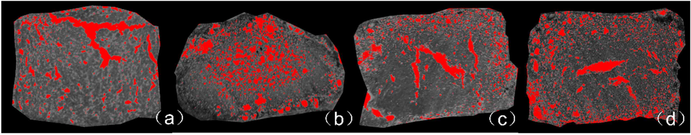
The imageJ gray scale analysis method was used to analyze the pore characteristics of ceramsite under 10% sodium carbonate foaming agent at different tempera- tures, and the results are shown in Fig. 2. When the gas first generated, it partially broke through the structure, forming larger pores as shown in Fig. 2(a). After the gas escaped from the loose structure of the top, as the temperature rose, the rate of gas generation became faster. This process increased the cavity size (Fig. 2(b)). Most of the small cavities resided in the centers of the ceramsite samples. When the small cavities gathered together, the cavities moved through the ceramsite, forming long and narrow pores in the ceramsite. Once the cavities reached the ceramsite surfaces, a low number of small bubbles formed near the glaze surface (Fig. 2(c) and (d)). When the small bubbles on the surface converged at 1100 oC, the void ratio rebounded. Since the large cavities had exited in the previous stage, the number of small bubbles was not increased from the previous stage, so the void ratio did not further rise. confirming that the foaming agent played an important pore-forming role in the ceramsite. From the images in Fig. 2, the gaps were inferred to form as follows: 1) Generated gas lifted the surface of the ceramsite; 2) small bubbles inside the ceramsite merged into larger bubbles; 3) the large bubbles moved from through the ceramsite and eventually escaped; 4) as the large bubbles were removed, more bubbles were transferred from the center to below the glaze.
The changes of the ceramsite compressive strengths are shown in Fig. 1(b). The results showed that the temperature had great influence on the compressive strengths of the ceramsite. When the temperature increased from 900 oC to 950 oC, the gas escaped from the small gaps in the raw material, and the fine soil particles could overlap but not melt together. The grains remained loose and the strength was not high at this time. After heating, the glaze thickened and wrapped the ceramsite, increasing the overall strength of the material. In addition, the SiO2 and Na2CO3 reacted at the higher temperature, generating more Na2SiO3 as shown below:
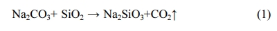
This reaction further increased the compressive strength of the ceramsite. The strengths of the 5% Na2CO3 and 10% Na2CO3 ceramsites peaked at 25.2 MPa (1050 oC) and 18.36 MPa (1030 oC), respectively. These differences were attributed to the different internal viscosities of the ceramsites with different Na2CO3 contents. At these temperatures, the compressive strengths of the ceramsites far exceeded those of similar light aggregates in previous studies [25, 26]. The compressive strength was lowest at 1090 oC, when the cavities generated by the tiny bubbles moved through the ceramsite forming vertical holes, just as shown in Fig. 2(c). The gas enclosed in the holes formed their own holes through the molten glass phase [27], and the compressive strength decreased accordingly. The minimum compressive strength was followed by a slight increase as the large cavities exited the glaze, and the liquid-phase part blocked the depressions left by the escaped cavities, forming a compact internal structure with increased strength. Meanwhile, the control experiment showed that without Na2CO3, the compression resistance of ceramsite was not effectively improved. Therefore, Na2CO3 played a dual role of pore formation and strengthening in the ceramsite.
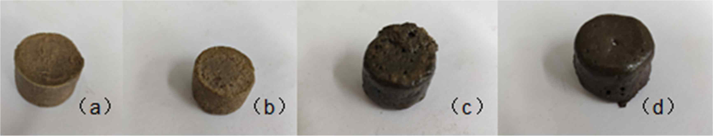
The changes of the ceramsite apparent densities are shown in Fig.1 (c). When the temperature rose from 900 oC to 950 oC, the ceramsite surface had not yet reached solid–liquid equilibrium, and the gas formed a cavity under the surface. At this time, the volume of the ceramsite increased slightly, just shown as Fig. 3(b), reducing the apparent density. After 950 oC, the liquid phase in the surface layer gradually increased and filled the cavities formed in the sintering stage within sufficient time, causing the surface to shrink. The apparent density slowly increased at this stage. After 1030 oC, the densities of the 5% and 10% Na2CO3 ceramsites were markedly different. From 1030 to 1070 oC, the density of the 5% Na2CO3 ceramsite was little changed, whereas that of the10% Na2CO3 continued decreasing. The high temperature increased the plasticity of the ceramsites, and the trace gas traveling through the ceramsite collected inside the ceramsite. The hard 5% of the surface blocked the internal gas from escaping the glaze, and a dense melt chamber was formed; consequently, the liquid phase could not freely flow and settle [28], and the weight and volume remained almost unchanged. However, the surface of the 10% Na2CO3 ceramsite was softer at this temperature, as evidenced from the melted edges and corners of the ceramsite in Fig. 3(d). This observation proves that the ceramsite simultaneously collected and expanded trace gases, causing a rapid drop in apparent density at 1090 oC. The apparent densities of both the 5% and 10% Na2CO3 ceramsites were smallest (1178.3 and 1295.0 kg/m3, respectively) at this temperature. At 1100 oC, the apparent density slightly recovered as the large cavities formed in the previous stage escaped the ceramsite glaze. At this time, many liquid phases blocked the gas escape, and the volume reduction raised the apparent density. In the ceramsite without the foaming agent, the apparent density was always relatively high. Although the density decreased after 1030 oC, it con- sistently remained above those of the ceramsites with the foaming agent. In addition, the Archimedes method should always give a higher ceramsite density in the control than in the experimental samples, because the ceramsite without foaming agent adsorbed water at a higher rate during the water absorption test.
Fig. 1(d) plots the water absorption changes in the ceramsites with different Na2CO3 contents as functions of temperature. In both ceramsites, the water absorption decreased with increasing temperature. The initial water absorption rates of 30.64% (5% Na2CO3) and 35.03% (10% Na2CO3) were reduced to 1.35% (5% Na2CO3) and 1.16% (10% Na2CO3) at the highest firing tem- perature. In general, the water absorption of ceramsite is closely related to the number, shape, and direction of openings on the ceramsite surface. A porous surface will absorb more water than a surface with few holes. Closed-cell pores also effectively reduce the water absorption, and a downward opening direction counters the escape of gas from the pores. All of these morpho- logies effectively reduce the water absorption. During the heating process, the ceramsite became tightly wrapped by the glaze, which sealed the open-pore structure of the ceramsite surface. Consequently, the water molecules were blocked from the ceramsite interior during the water absorption experiment.
Thermodynamic behavior in the process of LWA firing
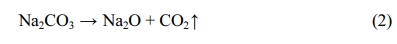
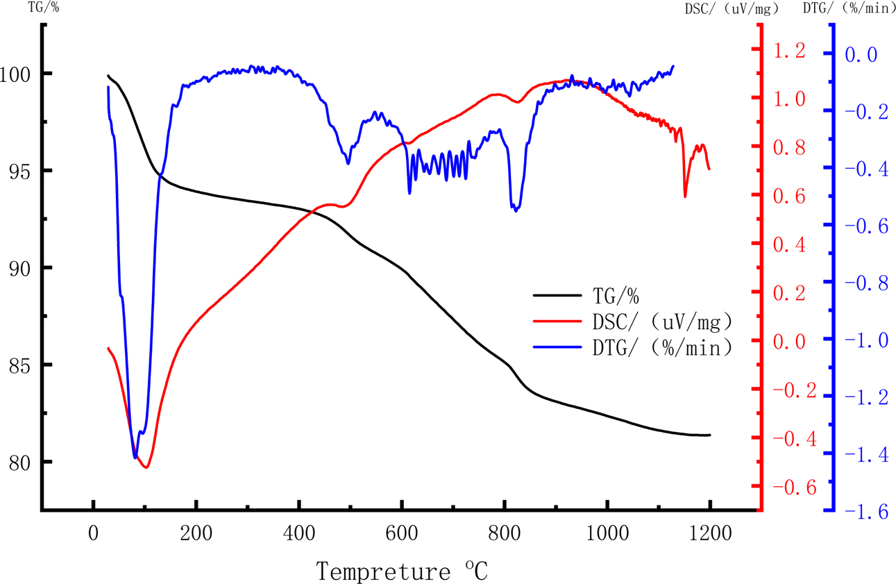
Thermogravimetric analysis (TGA) curve shows the characteristic temperature behavior, thermal weight loss corresponding to heat absorption, and the release peak of the mixture during sintering. The TGA results provide a reference for understanding the foaming mechanism of raw meal. The thermogravimetry (TG), differential scanning calorimetry (DSC), and Derivative thermo- gravimetry (DTG) curves of the raw material with 10% Na2CO3 are shown in Fig. 4. The TG curve exhibits two obviously declining stages during the firing process, one located between 30 and 100 oC, the other between 400 and 800 oC. The first declining stage is mainly explained by moisture evaporation from the raw material. During this stage, the ceramsite lost 5.8% of its weight, indicating that the moisture content was reduced by drying at 120 oC for 20 min. Meanwhile, the trough in the DSC curve indicated an endothermic reaction at this stage. During the second declining stage, the TG reduced by approximately 10%. As the raw material contained less than 10% Na2CO3, this stage was attributed to dissolution of the carbonate contained in the OS semi-coke, accompanied by sulfide volatilization and a small amount of decomposed, volatized organic matter. The DTG curve exhibited troughs at 500 and 800 oC. Two different reactions resulted in carbide and sulfide losses between 400 and 500 oC, and sodium carbonate began decomposing around 820 oC [29]. Unlike redox foaming agents, decomposition foaming agents are unaffected by the external environment, so the experimental error is reduced [30]. The foaming principle of Na2CO3 is
The DSC curve during the heating process reveals that Al, Mg, Si, and other elements reacted with each other. Because most of these reactions were chemical reactions, a large amount of heat was exothermic. The exothermic reaction began weakening at 950 oC, when the glaze formed and the ceramsite surface began changing to the glass phase. The sudden change at 1100 oC might cause overheating. To avoid this situation, the sintering time of the 10% Na2CO3 ceramsite should be controlled between 950 oC and 1100 oC.
Crystal phases and chemical composition analyses
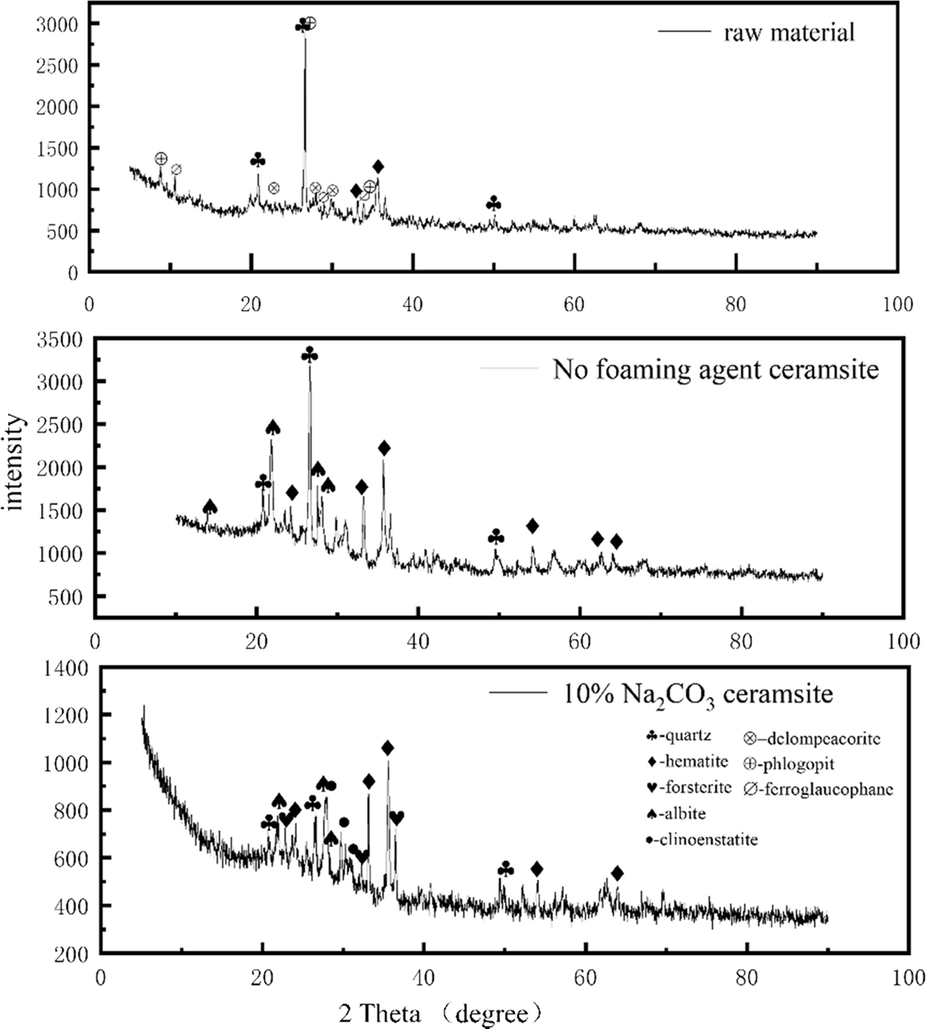
Fig. 5 shows the XRD patterns of the raw material and porous ceramsite. The raw meal mainly contained quartz, hematite, donpeacorite, phlogopite, and ferro- glaucophane. The main elements in quartz and hematite were Si and Fe, respectively. Phlogopite and ferro- glaucophane were dominated by Al, while donpeacorite mainly contained Mg. The quartz minerals enhanced the glass phase during heat treatment, while the clay minerals enabled the expansion process [32]. From a microscopic viewpoint, the crystalline material in the ceramsite raw material intensified the atomic thermal vibrations as the temperature increased, and the order of the atomic arrangement was gradually destroyed. This amorphous transformation was necessary for reaching the molten state. After firing, quartz and hematite remained in the ceramsite, but new minerals such as forsterite, albite, and clinostatite were formed. Albite formed a framework of mineral component in the siliceous aggregate [17, 33]. The liquid phase was formed during the firing process and compacted the ceramsite by filling the gaps in the framework. Albite is also a common component of feldspar rock and often exists in the siliceous mineral aggregates of concrete [34]. The appearance of albite shows that Na2CO3 and SiO2 and Al2O3 in the raw material reacted during the ceramsite formation. Si in the silica tetrahedral network was replaced by Al, forming an aluminum tetrahedral structure [35]. As trivalent aluminum could replace the necessary tetravalent silicon, a positive charge must have compensated the tetrahedrally coordinated aluminum to maintain electrical neutrality [36]. These positive charges were provided by other cations [37], such as Na+. Because of its high Mohs hardness and its special frame-like structure, albite wrapped and bonded the surrounding materials, enhancing the mechanical strength of the ceramsite. The fired ceramsite also contained forsterite, a silicate mineral with an island structure. The high-strength characteristics of ceramsite imply that magnesium was chemically active and easily attracted by nearby aluminum or silicon tetrahedrons, where it reacted with aluminum or silicon to form a new crystal phase [38]. The Mg from enstatite in the raw meal and Si in quartz underwent ion replacement, crystal rearrangement, decomposition, redox, and other reactions, forming some magnesium aluminosilicates. At this stage, the following reaction occurred:
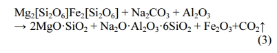
During the heating process, part of the enstatite in the raw meal was converted into another form, clinoenstatite, with similar properties to enstatite.
Morphological structure analyses
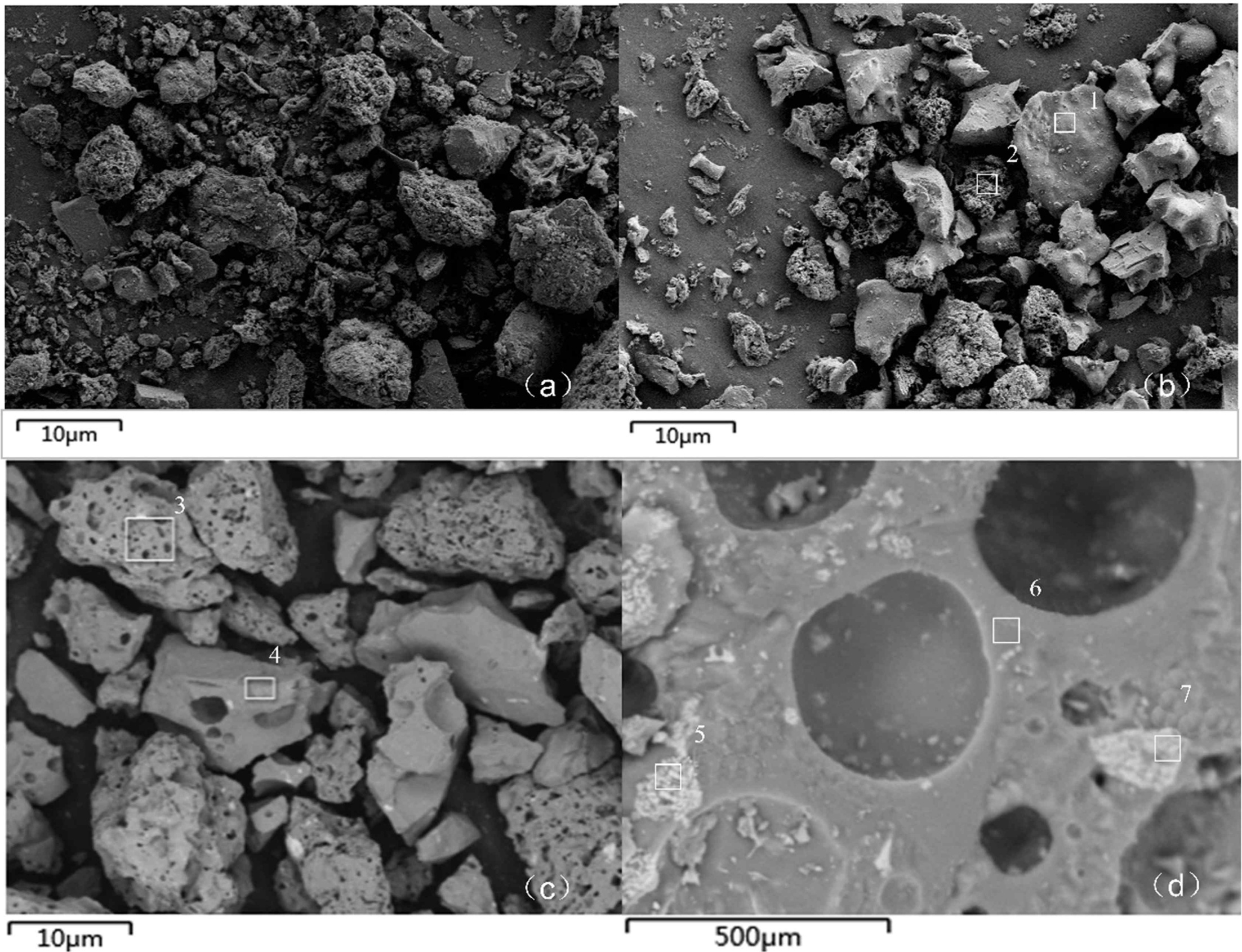
The SEM image of raw meal shows a loose structure with a rough surface and a relatively uniform distribution of minerals (Fig. 6(a)). The sample fired without the foaming agent exhibited both dense (Fig. 6(b)-1) and loose (Fig. 6(b)-2) areas. After scanning these areas with energy-dispersive X-ray spectroscopy (SEM-EDX), the proportions of atoms differed from those of the raw material. The dense areas contained increased quantities of Al and Si, and a small amount of Na, suggesting a mineral phase change to albite (Na2OAl2O36SiO2). In the loose areas, the Mg content was increased but had not reached the required temperature for the formation of mafic or forsterite minerals [31]. Therefore, no sup- porting minerals that would improve the compressive strength had formed at this time. Moreover, the new mineral albite could melt within the mineral gaps. On the ceramsite surface, which is more susceptible to heat than its interior, the openings were easily filled by albite, and the glaze became more complete, filling most of the surface holes. Comparing these results with that of the control, we inferred that the foaming agent was closely related to glaze formation, and hence to the decreased water absorption of ceramsite. The gas produced by the organic matter in 0% Na2CO3 ceramsite could not form pores at the existing ratio of raw materials. After adding the foaming agent (Fig. 6(c)), porous (Fig. 6(c)-3) and dense (Fig. 6(c)-4) areas appeared, and the pores were uniformly distributed in the porous area. SEM–EDX (Fig. 6(c)-3) revealed a predominance of Mg and Na in the porous and dense areas, respectively, indicating that the tight and porous areas were partially fused with each other. A high-magnification image of the porous area (Fig. 6(d)) revealed other minerals scattered on a frame-like struc- ture interspersed with holes. Forsterite (Fig. 6(d)-5) and hematite (Fig. 6(d)-6) were identified as the main minerals, while the main structure was dominated by albite (Fig. 6(d)-7). The forsterite was distributed on the pore-filled ceramsite, and hematites with higher hardness were embedded in the albite framework, increasing the pressure resistance of ceramstite.
|
Fig. 1 Temperature dependences of the physical properties of ceramsites with different Na2CO3 contents: (a) Porosity, (b) compressive strength, (c) apparent density, (d) water absorption |
|
Fig. 2 ImageJ analyses of the 10% Na2CO3 ceramsite cross-sections at different temperatures: (a) 950 oC, (b) 1070 oC, (c) 1090 oC, (d) 1100 oC. |
|
Fig. 3 Surface morphology of 10% Na2CO3 at different temperatures: (a) 900 oC, (b) 950 oC, (c) 1070 oC and (d) 1090 oC |
|
Fig. 4 Thermogravimetric analysis of 10% Na2CO3. |
|
Fig. 5 XRD spectra of raw materials, ceramsite with no foaming agent and 10%Na2CO3. |
|
Fig. 6 SEM images of raw meal and ceramsites: (a) Raw material, (b) 0% Na2CO3 ceramsite at 1070 oC, (c) 10% Na2CO3 at 1070 oC ceramsite (80× magnification), (d) 10% Na2CO3 ceramsite at 1070 oC (4000 × magnification). |
The effects of Na2CO3 on ceramsite prepared from demagnesium boron mud and oil shale semi-coke were studied. The main conclusions of the study were summarized as below:
1. The dosage of sodium carbonate had a great influence on the performances of ceramsite fired from the main raw materials of demagnesium boron mud and oil shale semi-coke. When the temperature was 1070 oC, with adding 10% Na2CO3, the porosity, com- pressive strength, apparent density and water absorption of ceramsite reached 22.63%, 11.50 MPa, 1398.33 kg/m3 and 1.43%, respectively. The performances of ceramsite met the requirements of light weight and high strength.
2. Using ImageJ grayscale analysis method to explore the foaming law in the ceramsite firing process, it was found that the temperature had a significant influence on the foaming process of ceramsite. When the firing temperature was low, the gas generated by Na2CO3 decomposition was difficult to escape due to insufficient melting of the surface of the ceramsite, and it accumulated inside the ceramsite to form a large cavity. However when the firing temperature was too high, the molten mineral inside the ceramsite quickly filled the pores, which caused the bubbles to be mainly distributed on the outer surface of the ceramsite.
3. Through the phase analysis of the high-strength lightweight ceramsite prepared with Na2CO3 as the foaming agent, it was found that the quartz, phlogopite, hematite, amphibole and enstatite in the raw meal were converted into albite and magnesium Olivine and clinostatite form a structure with forsterite as filling and albite as skeleton, which could promote the firing of ceramsite with high strength and low density.
This study was funded by the National Key Research and Development Plan Subject for Monitoring, Early Warning and Prevention of Major Natural Disasters (2017YFC1503105) of China. Special thanks are due to the instrumental or data analysis from Analytical and Testing Center, Northeastern University, China.
- 1. X.-J. Fu, M.-S. Chu, J.-Q. Zhao, S.-Y. Chen, Z.-G. Liu, and S.-Y. Wang, High Temp. Mater. Processes 36[7] (2017) 649-655.
-

- 2. J. Bo, Y. Zhang, and Y. Zhang, Hydrometallurgy 171 (2017) 142-148.
-
- 3. R. Boncukcuoğlu, M. M. Kocakerı̇m, V. Tosunoğlu, and M. Tolga Yilmaz, Cem. Concr. Res. 32[1] (2002) 35-39.
-
- 4. W. Wang, H.M. Gu, and Y.C. Zhai, Adv. Mater. Res. [881-883] (2014) 671-674.
-
- 5. Z. Q. Ning, Y. C. Zhai, H. W. Xie, Q. S. Song, and K. Yu, Rare Metals. 35[2] (2016) 204-210.
-
- 6. M. Torres, J. Castiglioni, L. Yerman, L. Suescun, B. Conti, M.M. Demarco, P. Gristo, P. Portugau, and A. Cuna, Fuel 234 (2018) 347-357.
-
- 7. S. Al-Asheh, F. Banat, and A. Masad, Environ. Geol. 44[3] (2003) 333-342.
-
- 8. K.M. Ibrahim, and J.O. Jaber, Environ. Geol. 52[5] (2006) 979-984.
-
- 9. X. Fu, J. Wang, Y. Zeng, F. Tan, and X. Feng, Environ. Earth Sci. 70[3] (2012) 1125-1134.
-
- 10. H. Jiang, M. Zhang, J. Chen, S. Li, Y. Shao, J. Yang, and J. Li, Fuel 200[200] (2017) 218-224.
-
- 11. H. Qin, W. Wang, H. Liu, L. Zhang, Q. Wang, C. Shi, and K. Yao, Appl. Therm. Eng. 120[2017] (2017) 19-25.
-
- 12. X. Li, X.-S. Shi, M.-Y. Lu, Y.-Z. Zhao, R.-B. Guo, and H. Peng, J. Hazard. Mater. 388 (2020) 121742.
-
- 13. Y. Lu, J. Xu, W. Wang, T. Wang, L. Zong, and A. Wang, Adv. Powder Technol. 31[6] (2020) 2276-2284.
-
- 14. Y. Wang, Z. Liu, J. Zhang, R. Mao, and Y. Zhang, J. Hazard. Mater. 381 (2020) 120902.
-
- 15. X. Chen, Z. Xu, Z. Yao, Q. Shuai, Z. Jiang, X. Peng, Y. Li, R. An, X. Jiang, and H. Li, Environ. Sci. Pollut. Res. 27[17] (2020) 20904-20911.
-
- 16. A. Bayoussefa, M. Loutou, Y. Taha, M. Mansori, M. Benzaazoua, B. Manoun, and R. Hakkou, J. Cleaner Prod. 280[P1] (2021) 124361.
-
- 17. Y.M. Wie, and K.G. Lee, J. Korean Soc. 57[6] (2020) 220-230.
-
- 18. Z. Zhang, J. Wang, L. Liu, and B. Shen, Ceram. Int. 45[16] (2019) 20058-20065.
-
- 19. S. Allaoui, M.N. Bennani, H. Ziyat, O. Qabaqous, N. Tijani, N. Ittobane, and L. Yu, J. Chem. 2020[11] (2020) 1-11.
- 20. Z. Zhang, L. Zhang, and A. Li, Waste Management (New York, N.Y.) 46 (2015) 316-321.
-
- 21. S.H. Aljbour, Oil Shale 33[3] (2016) 260-271.
-
- 22. J. Luan, A. Li, T. Su, and X. Cui, J. Hazard. Mater. 173[1-3] (2010) 427-432.
-
- 23. J. Maosa, J. Formosa, J. Giro-Paloma, A. Maldonado-Alameda, M.J. Quina, and J.M. Chimenos, Constr. Build. Mater. 269 (2021) 121335.
-
- 24. H. Wu, T. Zhang, R. Pan, Y. Chun, H. Zho, W. Zhu, H. Peng, and Q. Zhang, Constr. Build. Mater. 171 (2018) 367-376.
-
- 25. T.Y. Lo, W.C. Tang, and H.Z. Cui, Build. Environ. 42[8] (2007) 3025-3029.
-
- 26. D. Rumsys, E. Spudulis, D. Bacinskas, and G. Kaklauskas, Materials 11[12] (2018) 2434-2434.
-
- 27. M. Liu, X. Liu, W. Wang, J. Guo, L. Zhang, and H. Zhang, Ceram. Int. 44[4] (2017) 4313-4319.
-
- 28. X. Li, P. Wang, J. Qin,Y. Liu, Y. Qu, J. Liu, R. Cao, and Y. Zhang, Constr. Build. Mater. 240 [2020] 117919.
- 29. J.W Kim, and H.G. Lee, Metall. Mater. Trans. B 32[1] (2001) 17-24.
- 30. Y.-H. Niu, X.-Y. Fan, D. Ren, W. Wang, Y. Li, Z. Yang, and L. Cui, Mater. Chem. Phys. 256 (2020) 123610.
-
- 31. F. Tavangarian, A. Fahami, G. Li, M. Kazemi, and A. Forghani, J. Mater. Sci. Technol. 34[12] (2018) 2263-2270.
-
- 32. R. Bouachera, R. Kasimi, M. Ibnoussina, R. Hakkou, and T. Yassine, Mater. Today: Proc. 37[P3] (2021) 3866-3870.
-
- 33. J. Mei, T. Wang, H. Peng, G.A. Ayoko, J. Liu, T. Liao, and Z. Sun, Adv. Sustainable Syst. 4[7] (2020) 2000057.
-
- 34. Y.H. Hsiao, E.C. La Plante, N.A. Krishnan, Y. Le Pape, N. Neithalath, M. Bauchy, and G. Sant, J. Phys. Chem. A 121[41] (2017) 7835-7845.
-
- 35. C.T. Li, W.J. Lee, K.L. Huang, S.F. Fu, and Y.C. Lai, Environ. Sci. Technol. 41[8] (2007) 2950-2956.
-
- 36. M. Zhou, X. Ge, H. Wang, L. Chen, and X. Chen, Ceram. Int. 43[12] (2017) 9451-9457.
-
- 37. M. Liu, J. Guo, and Y. Shao, Constr. Build. Mater. 259 (2020) 120398.
-
- 38. Y. Pristinskiy, N.W.S. Pinargote, and A. Smirnov, Mater. Today: Proc. 19[Pt 5] (2019) 1990-1993..
-
 This Article
-
2021; 22(6): 597-604
Published on Dec 31, 2021
- 10.36410/jcpr.2021.22.6.597
- Received on Jan 27, 2021
- Revised on May 22, 2021
- Accepted on Jun 3, 2021
Services
- Abstract
introduction
materials and methods
results and discussion
conclusions
- Acknowledgements
- References
- Full Text PDF
Shared
Correspondence to
- L. Liang
-
Department of Environmental Engineering, School of Resource and Civil Engineering, Northeastern University, Shenyang 110000
Tel : +86-18624058030 Fax: +86-024-83679128 - E-mail: liliang@mail.neu.edu.cn
Clean-Energy Research Institute(CRI), Hanyang University, 222, Wangsimni-ro, Seongdong-gu, Seoul, 04763, Korea
E-mail: jcpr@hanyang.ac.kr