


- Effect of ceramic fibers, metal fibers and frictional additive (PG-902) on the properties of Non-Asbestos brake pads
P. Baskara Sethupathi and J. Chandradass*
Centre for Automotive Materials, Department of Automobile Engineering, College of Engineering and Technology, SRM Institute of Science and Technology, Kattankulathur, 603203, India
This article is an open access article distributed under the terms of the Creative Commons Attribution Non-Commercial License (http://creativecommons.org/licenses/by-nc/4.0) which permits unrestricted non-commercial use, distribution, and reproduction in any medium, provided the original work is properly cited.
Environmental legislation's in the US have questioned the role of multifunctional copper fibers/powders in non-asbestos brake pads. Other heavy metals like Iron, chromium, Tin, Zirconium from wear particles of brake pads and zinc from tyres dislodged into storm water. They discharge into waterways which affects the lives of invertebrates in the water. In this context, the present research work attempts to compare a formulation devoid of metals i.e ceramic fibres, friction additives with that of metal without compromise in the tribo performance. The parent formulation consists of 86%, and the rest is varied with Ceramic fibers (NANM), Cu and Brass fibers (NACB), Steel wool (NASW). Furthermore, applying commonly used metal sulfides with natural graphite (NAGR) and a specialty additive, namely PG902 (NAPG) using polarized graphite developed in-house, was also studied. An investigation was carried out on all the developed brake pads to identify the performance mechanism, which revealed interesting results. The surface morphology of brake pad was studied by Scanning Electron Microscopy. The analysis concluded that Additive PG-902 played a significant role as transfer film, which is neither due to sulfur effect nor reaction product effect. This film layer is responsible for the stable friction and wear life of the friction couple
Keywords: Non-Metallic brake pad, Eco friendliness, Polarized Graphite, Steel Wool, Transfer film
The various mechanisms and materials to slow down and stop the vehicle remain a mystery to common people. Frictional material manufacturers develop brake pads and validate through vigorous testing protocols and iterations to select the best materials and the optimum quantity. They do so because the brake pad materials are complex and vary widely depending upon the type of vehicle. Fast-moving commercial brake pads include semi-metallic, metallic and organic brake pads, which are inexpensive. On the negative side, metallic brake pads produce a lot of dust and noise and below-par performance under extreme conditions. Besides, wear debris from the brake system contribute toxic heavy metals to the environment. Heavy metals include chromium, copper, Tin, Zirconium, Zinc, cadmium, lead and lead compounds. Heavy metals also pollute soil by road runoff from cars damage crops and other food sources [1]. However, heavy metals appearing in the environment gutters and go through stormwater and discharges into waterways affecting the life of aquatic species [2-4]. The study was conducted based on the copper wear debris and their impact on salmon fish species survival. Accordingly, copper usage is restricted and as per the California senate bill 2010, 0.5% copper is permitted up to 2025. This is followed by the development of copper-free brake pads by researchers worldwide [5-8]. The quantum of work was carried out by utilizing high conductivity carbonaceous components for faster heat dissipation [9-11].
Most of the researchers mentioned above scope were to reduce or eliminate a single metal, namely copper, in the formulation. In this context, the present research work attempts to compare a formulation devoid of metals with that of metal without compromise in the tribo performance. The parent formulation consists of 86% and the rest is varied with Ceramic fibers (NANM), Cu and Brass fibers (NACB) and Steel wool (NASW). Furthermore, the application of commonly used metal sulfides with natural graphite (NAGR) was also studied during this research work. Also, a specialty additive, namely PG902 using polarized graphite, was developed in-house at Fricmart. The same was used in the final formulation (NAPG). All the brake pads are developed as per Industrial procedure. The influence of these different ingredients on the different formulation has been analyzed by examining the physical, thermal and mechanical properties such as density, hardness, porosity, shear strength (hot & cold) and thermal conductivity. Tribo performance is studied using the Chase testing machine following SAE J661 standards. The analysis of the obtained results was supported by the character- ization using Scanning Electron Microscope (SEM) on the tested pads surface.
The friction composite fabrication was based on keeping parent composition of 86 wt% constant and varying ceramic fibers, Cu & brass powders, Steel wool, Natural graphite with commercial metal sulfides and PG 902, a specialty additive in each composition. The detailed ingredients in the formulation are shown in Table 1. Percentage weight of ingredients was adjusted not to change% volume in each composition to maintain porosity level between 6 and 8.
All ingredients were weighed according to Table 1 and dry mixed for 6 min in a plough shear mixer. The formulation was hot-pressed at 145 oC under 30 MPa for 3 min. During curing, mold was released several times to eliminate the volatiles. Finally, the post-curing was carried out in an oven with a bump cycle; 150 oC for one hour and 200 oC for four hours. The samples were then grounded to remove resinous skin and to get a good surface finish.
Characterization of brake pads and evaluation of friction performance
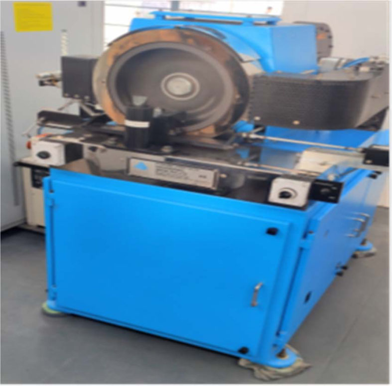
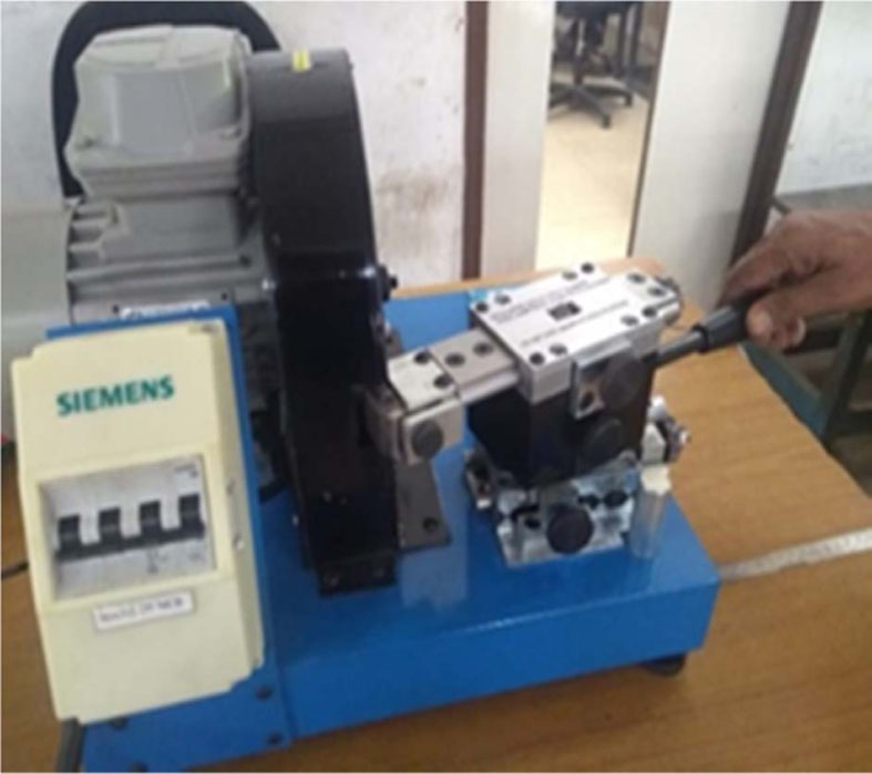
Brake pads were characterized for physical properties such as density (by water immersion method) and porosity (JIS-D 4118 standard) by picnometry. Thermal conductivity test was conducted using Thermal conduc- tivity analyzer (FL-3000) after cutting the brake pad to the size of 10 mm x 10mm and thickness of 2.5 mm. The surface is coated with graphite spray and measure- ments were carried out at 150 oC and 400 oC. Hardness is calculated in ‘S’ Scale using a Rockwell testing machine with a major load of 100 kgf. Shear strength (ISO 6312) is found by determining the force required to detach the friction material from the back plate by the pad surface area. For hot test, the pad is heated to around 200 oC and the same procedure is repeated. The friction performance was evaluated according to SAE J661 procedure in Indian Friction Material Engineering Company using a Chase Testing machine shown in Fig. 1. The sample of size one inch by one inch and thickness 8 mm is cut from the brake pad for testing purposes. The detailed test schedule is explained elsewhere [12]. The sample was then ground to precision to suit the diameter of the drum by developing a special grinding machine for this purpose (Fig. 2)
Faster bedding was achieved by precision grinding. The wear of worn pads was estimated from the thickness as well as mass losses obtained from measurements before and after the chase test. The surface morphology to understand the wear mechanism was studied using Field Emission Scanning Electron Microscopy (FESEM).
|
Fig. 1 Chase Testing Machine. |
|
Fig. 2 Sample grinding machine. |
|
Table 1 Formulations (wt.%) |
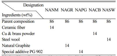
Binder (Phenolic resin, rubber) 11wt%, friction modifiers (alumina, MgO, Fe3O4) 3 wt%, Reinforcements (Kevlar, PAN, various fibers) 15.5 wt%, Organic fillers (friction dust, CPC) 12 wt%, Inorganic fillers (cryolite, feldspar, barytes, calcites, lime) 33.5 wt%, Lubricant (FeS, CuFeS, Syn.graphite) 11 wt%. |
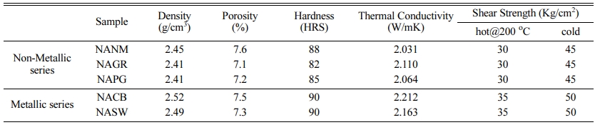
Properties of the brake pads
Table 2 lists out various physical and mechanical properties of the developed brake pads as there is always a close relationship between the physical pro- perties and the frictional behavior. From the tabulated results, density and hardness values are slightly higher for the metallic series (NACB & NASW) brake pads than the non-metallic series. This is expected due to the higher density of the metallic elements than the organic/inorganic counterparts. A direct relationship between hardness and wear resistance was reported by many researchers [13, 14], which are still under profound debate. As seen in the wear section, brake pads with higher hardness didn’t show wear resistance. Strong adhesion between metal fibers with the resin matrix improved the shear strength (both hot and cold) [15]. Metallic series-based brake pads possessed greater thermal conductivity due to metal greater thermal conductivity than the non-metallic series. For brake pads with poor thermal conductivity, frictional heat will be accumulated inside, causing degradation of resin and accelerating wear which can be observed in the wear results.
Friction and wear performance
The performance CoF is calculated as an average CoF of Fade and recovery cycles above 100 oC.
Almost all the friction composites had similar perfor- mance which are acceptable as per industrial standards. Since, the brake pads are rated by their resistance to fade, fade cycles are studied in detail.
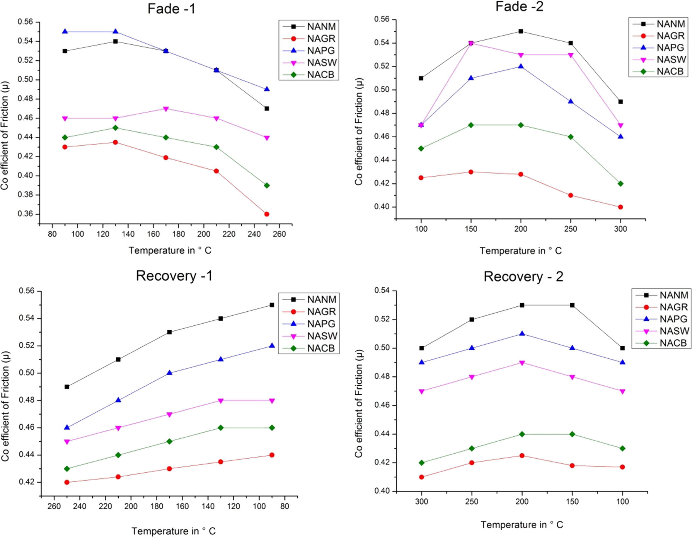
The gradual increase of µ up to 150°C is attributed to the growth in the real area of contact at the interface between the brake pad and the disc. This trend can be noticed in most of the literature [16, 17]. Until 150 oC, there is a rise in µ. After that, the trend drastically changes. This change in µ is almost similar for all the friction composites. But the rapid change can be noticed more for metallic series and ceramic fibres.
In the case of NAGR, the fade1 µ for both the cycles is lesser than its counterparts. In the case of fade2, it is almost similar to NACB and comes under the least performer. Still the average fadeµ (fade1 & 2) is 0.382. For NAGR, dry sliding, wear particles are ground and gather /assemble on the friction surface to form the carbonaceous phase. Some parts may transfer to the disk to improve the adhesion characteristics. However, most of the organic compounds are non-polar, and graphite is not an exemption. Hence, graphite has poor adhesion to substrates, and film formation is not possible at elevated temperatures. Hence, within a certain tem- perature range (between 150 and 200 oC), graphite can increase the µ. However, as the temperature increases, graphite undergoes decomposition by thermal oxidation and loses its adhesion characteristics, which in turn reduces µ [18].
In NACB, thermal conductivity is best among the other developed composites, which can be verified by the time taken to reach the maximum temperature. (ref table 3). In literature, it was reported that consistent µ was obtained when using copper fibers in friction materials due to the formation of copper oxides at the interface [19]. But in the present case, it is slightly different. In the case of NASW, there is a drop in µ only after 200 oC.This is possible because, for the same wt%, the lower density of steel wool compared with the copper and brass causes more volume of steel wool reinforcement, which paves the way for more amount of primary plateaus formation [20]. Moreover, steel being more aggressive than Cu and Br causes fluctuation in µ [21].
The NANM sample (ceramic fiber-based) showed the highest performance CoF than other non-metallic series friction composite and the metallic-based friction composites. These ceramic ingredients being aggressive with poor thermal conductivity causes the rapid increase of the higher interface temperature, confirmed by the time taken for the maximum temperature rise (Ref Table 3). This faster temperature rise may degrade the phenolic resin, which loses its binding capacity [22]. The ceramic tends to remove the pyrolyzed film on the mating surface to cause torque variation during the braking application, which fluctuates the µ from 0.53 to 0.45 [23].
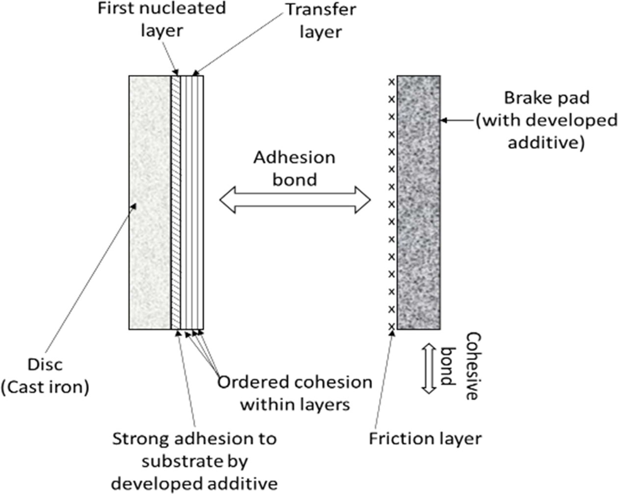
To improve the adhesion characteristics, attempts were made to change its polar structure by coating with various inorganic compounds such as metal sulfates, metal molybdates and metal phospates in micronized form homogeneously dispersed in graphite medium. Costlier metal sulfides are not considered for selection. NAPG contains polarized graphite, which forms continuous film by releasing alternating positive and negative charges. Unlike graphite which has poor adhesion property on the metal substrate, the Polarized graphite promotes film-forming ability at the substrate due to strong adhesion, as shown in the Fig. 4 [24].
This film called Tribological third body is chemically a solid-fluid mixture. This film is formed during the translation of kinetic energy to heat energy by combining thermo-chemical and plastic deformation of friction couple with strong adhesion to the disc surface. Like molecules of microfilm acts as a physical separation between the pad and the disc and protects the braking path from any damage and maintains consistent friction. Hence, the friction layer and transfer layer quality are responsible for stable friction, as noticed from both the fade cycles [25].
One of the important criteria for rating the friction material performance is friction stability, as the drivers expect the same degree of performance irrespective of diverse conditions.
In order to determine the friction stability, the following steps are done.
Di - Degree of the friction coefficient
μfa– Fade coefficient of friction (At temperatures increasing from 100 oC to 300 oC during second fade cycle))
μre – Recovery coefficient of friction (Temperatures decreasing from 300 oC to 100 oC during second recovery cycle)
Step 1:
Absolute difference in friction coefficients:

The smaller the dμ(T), the better
Step 2:
Normalized difference in friction coefficients:
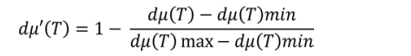
Step 3:
Optimized difference in friction coefficients:

Step 4:
Average difference in friction coefficients (optimized):(formulation results of different friction temperatures are averaged)
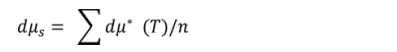
(n = 100,150, 200, 250, 300 oC)
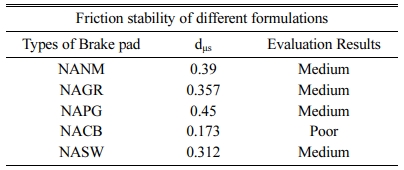
dμs =1~0.75 is excellent, dμs<0.75~0.5 is good, dμs = 0.5~0.25 is medium dμs<0.25 is bad
The friction stability of various formulations (Table 4) show that the friction stability of NACB belongs to poor. At the same time, all other brake pads come under the medium category. Here again, NAPG is the best among its competitors. This agrees with the discussion on the friction section.
Wear performance
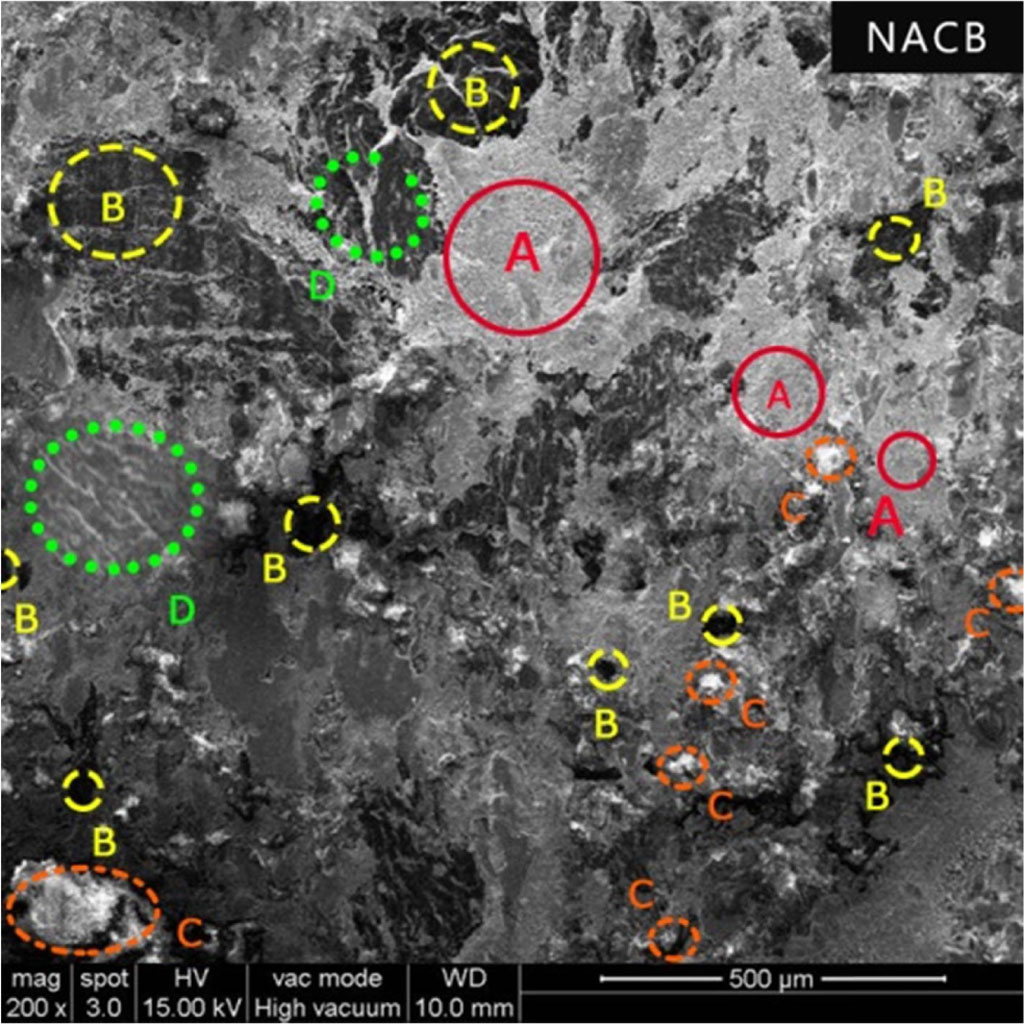
In terms of wear, considering the thickness loss, NACB is worse than the other samples. Despite good thermal conductivity, wear resistance is poor. The possible reason might be the addition of brass which contains 30% of zinc. This additional hardness will cause excessive wear due to scoring, which causes the surrounding neighbouring soft particles to degrade and wear.
Further, in work carried out by Sellami [26] with varying brass content on the brake pad, it was shown that the brass particles were pulled out of the matrix and ejected out of contact leading to excessive wear if the amount of brass particles are in large quantities (5 wt%). As can be noticed from the SEM images from the Fig. 5, the surface is covered with lots of plateaus and pits and cracks showing abrasive action of the metallic fibers. Also, the formation of the glazed surface is possible, which was noticed during the recovery cycle, which causes more fluctuation.
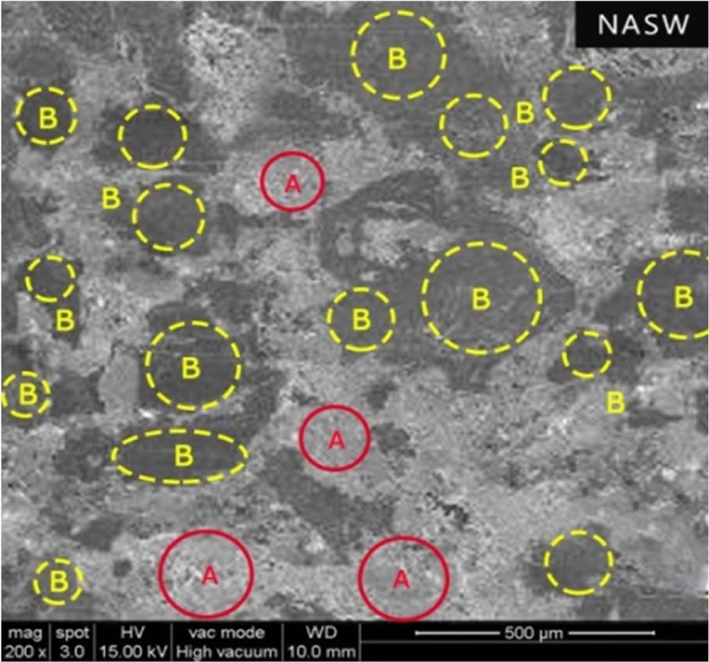
But in the NASW case, the wear resistance is comparably better because the steel wool has a high resistance to sliding wear than its counterparts and forms the central part of the contact plateaus. In addition, the amount of secondary plateaus formation dominates the primary plateaus, which enhances the wear resistance. This bears the higher portion of the load and prevents the softer ingredients from controlling the wear [27].
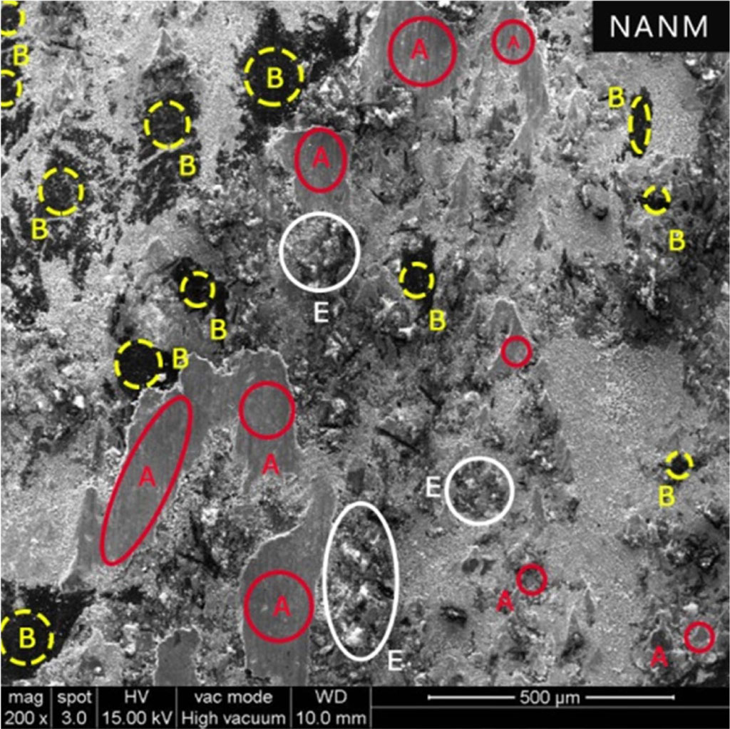
The wear resistance in terms of thickness loss of NANM containing more ceramic fibre is lesser than NACB despite poor conductivity and higher heat generation. More amounts of pits and worn-out particles could be easily observed due to its poor thermal conductivity and accumulation of the higher amount of heat at the interface, causing excessing worn-out particles as shown in Fig. 7.
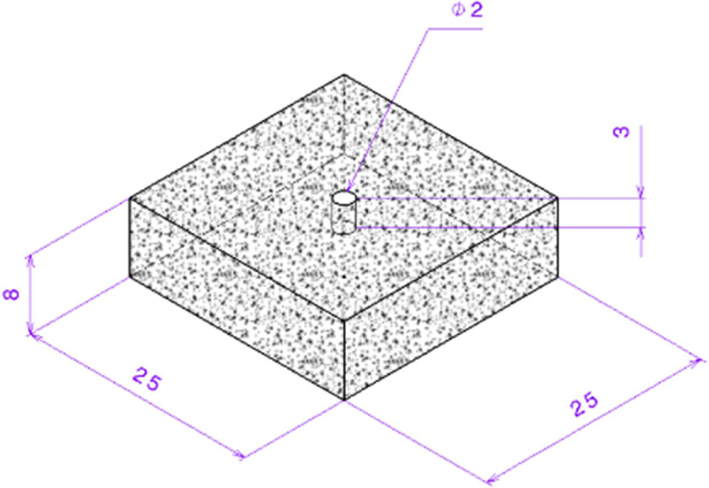
But the loss of mass is more than NACB. To analyze and reconfirm, another sample was tested in Chase. This time a small hole of diameter 2 mm and depth 3 mm is drilled on the top surface of the brake pad specimen. This is done in order to check the heat swell effect. The depth between the bottom of the hole and the reference surface is taken as the initial thickness. After testing, it was found that the loss in thickness is 0.74 mm instead of 0.69 mm.
This confirms that higher heat accumulation causes excessive heat swell, which is compensated in the thickness loss during wear test with a similar mass loss. This kind of test procedure seems to be useful for high heat generation formulation. This agrees with the work carried out by Sriwiboon et al. [28] by observing divergence in the disc pad wear by the thickness and weight loss measurement. Also, the data of thickness loss was taken with the Chase testing machine manufacturer M/s. Pyramid Precision Engineering for the entire test cycle includes all the fade, recovery and wears cycles. It was observed that during fade and wear cycles, there is a notable increment increase in thickness which is the indication of the swell.
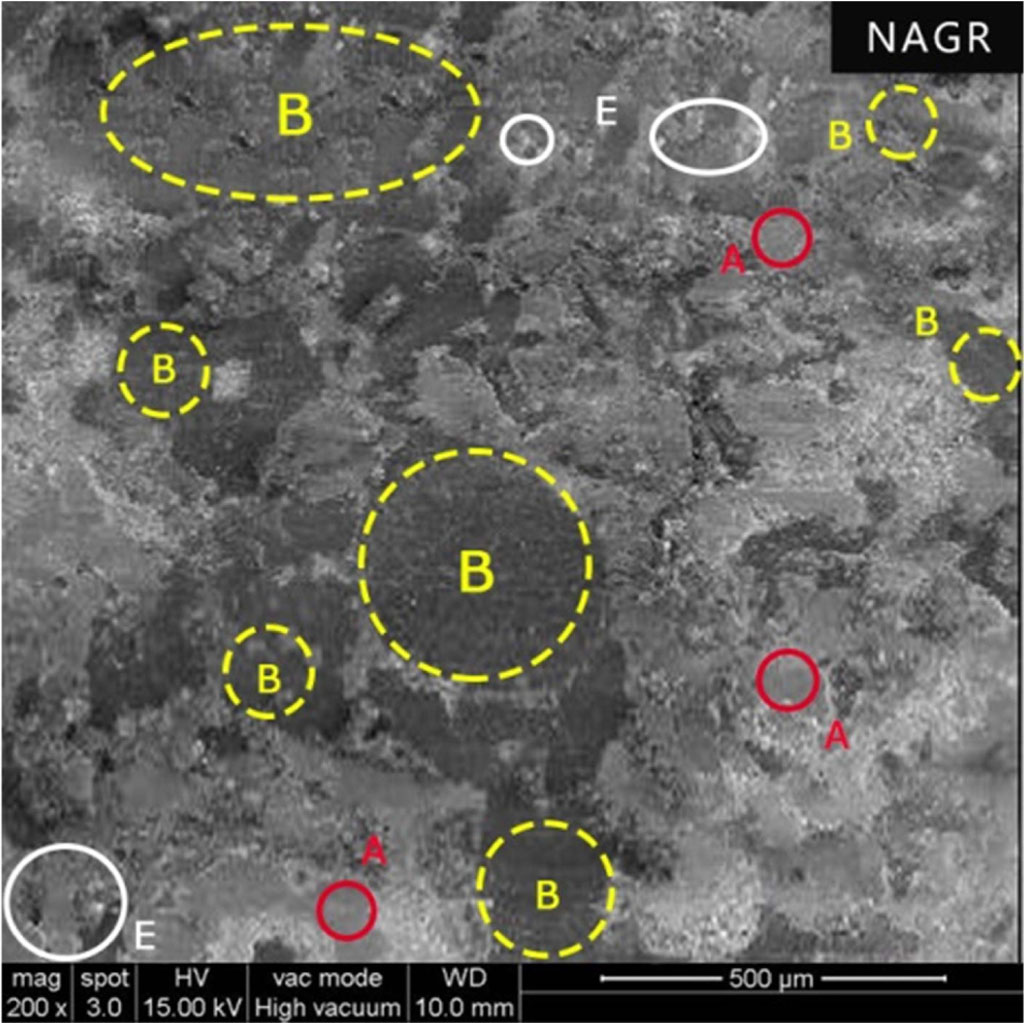
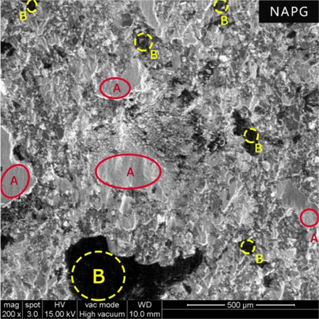
Despite more solid lubricant graphite (NAGR), wear resistance is poor compared to NAPG and NASW. Ordinary graphite has good lubricity but doesn’t possess electrical polarization. The lack of electrical polarity prevents ordinary graphite from forming a lubricant film / protective film and adhering to a metal surface (Brake drum or Disc / Rotor surface). Further, its lubricity depends upon humidity [29]. At high temperatures in the absence of water vapor, its lubrication decreases as water reduces the covalent bond degree between adjacent layers [30]. Moreover, organic ingredients like graphite at higher temperatures degrade. The worn-out particles are transferred to the disc and back to the pad forming secondary plateaus, which help minimize the wear. The SEM image in Fig. 9 indicates the secondary plateaus formed by these carbon particles, which is confirmed through elemental mapping. Also, the product of graphite oxidation is CO2 which, while releasing, causes massive wear loss. Figure 8 shows the limited amount of friction film, which quickly gets sheared, resulting in excessive wear.
NAPG with specialty additive PG-902 had excellent wear resistance. The electrical polarization of polarized graphite present in PG-902 additive results in the material having good adhesion to metal and forms microscopically thin lubricant film.
This protective coating called Tribological 3rd body over the mating surface carries an extremely high shear load without fracture or failure. The cohesive bonds within the transfer layer are supposed to be stronger than the adhesive forces between transfer layer and friction layer. But, still, there is a need to maintain high friction. So the transfer layer is removed by stress/fatigue/abrasion and now a new transfer film is formed from the reservoir of the composite, and thus the mechanism of wear occurs [31].
Unlike normal sulfide mix, PG-902 forms a continuous film or layer on the rotor surface during wear out by releasing alternatively positive and negative charges. The continuous film protects the braking path from damage and maintains consistent friction by acting as a physical separation between the opposing surfaces [32].
The elemental mapping shows the limited amount of free sulfur. Unlike commercial sulfide mix, for example, MoS2 in sulfide mix exhibits film-forming ability as the lamellae can slide over each other. However, sulfur is vaporized from the ‘sulfide mix’, which may have a corrosive effect in a humid environment. At elevated temperatures, SO2 fumes can diffuse into the rotor and form Moly Trioxide, where Mohs hardness increases from 1 to 6, resulting in the composite/matrix more aggressive [33]. Thus, the reduced wear is neither a sulfur effect nor reaction products effect when polar graphite additive plays the major role as Tribological 3rd body. Fig. 3 6 8 10 11
|
Fig. 3 Graphs showing Fade and Recovery behaviour of brake pads. |
|
Fig. 4 Schematic diagram of film formation using polarized graphite. |
|
Fig. 5 Surface morphology of NACB brake pad (A - Primary Plateaus, B - Secondary Plateaus, C – Pits and D – Cracks). |
|
Fig. 6 Surface morphology of NASW brake pad (A - Primary Plateaus, B - Secondary Plateaus). |
|
Fig. 7 Surface morphology of NANM (A - Primary Plateaus, B - Secondary Plateaus and E – Worn out Pericles) |
|
Fig. 8 Sample with drilled hole. |
|
Fig. 9 Worn surface of the NAGR (A - Primary Plateaus, B - Secondary Plateaus and E – Worn out Particles). |
|
Fig. 10 Worn surface of the NAPG (A - Primary Plateaus and B - Secondary Plateaus). |
|
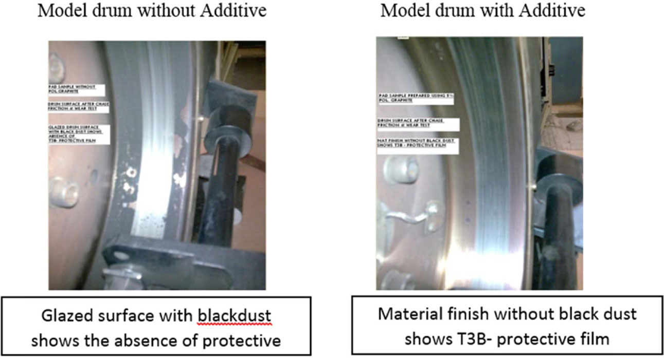
Fig. 11 Photograph of Brake drum after Wear Test. |
|
Table 3 Friction and wear performance parameters |
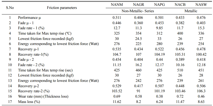
Table 3 lists out the various performance parameters obtained after chase testing. |
1. Non-metallic series composites developed higher µ when compared to metallic series with poor wear resistance.
2. Thermal conductivity alone cannot be the deciding factor for tribo-performance.
3. PG-902 stabilizes friction by alternatively releasing positive and negative charges to continuous film between transfer layers/friction partners.
4. The reduced wear is neither a sulfur effect nor reaction products effect when polar graphite additive plays the major role as Tribological 3rd body.
5. Controlled manufacturing of additives could eliminate the thermal conductivity the problem for the possible elimination of metals in the formulation which is helpful for the environment.
Authors gratefully acknowledge INDIAN FRICTION MATERIAL ENGG.CO. (FRICMART), Ghaziabad, Uttar Pradesh, India, for extending their facilities to carry out a part of this research work.
- 1. G. Valotto, D. Zannoni, P. Guerriero, G. Rampazzo, and F. Visin, Int. J. Environ. Sci. Technol. 16 (2019) 6513-6526.
-

- 2. J.F. Sandahl, D.H. Baldwin, J.J. Jenkins, and N.L. Scholz, Environ. Sci. Technol. 41[8] (2007) 2998-3004.
-
- 3. R.R. Ciudin, P.C. Verma, S. Gialanella, and G. Straffelini, WIT Trans. Ecol. Environ. 191 (2014) 1423-1433.
- 4. P. Baskara Sethupathi, J. Chandradass, and M.A. Saibalaji, Environ. Technol. Innov. 21 (2021) 101245.
-
- 5. N. Aranganathan, and J. Bijwe, Wear 352-353 (2016) 79-91.
-
- 6. P.W. Lee and P. Filip, Wear 302[1-2] (2013) 1404-1413.
-
- 7. R. Gilardi, L. Alzati, M. Thiam, J. Brunel, Y. Desplanques, P. Dufrenoy, S. Shanma, and J. Bijwe, Materials 5[1] (2012) 2258-2269.
-
- 8. P.W. Lee, L. Lee, P. Filip, SAE Int. J. Passeng. Cars. Mech. Syst. 6[3] (2013) 1389-1397.
-
- 9. H.Y. Lin, H.Z. Cheng, K.J. Lee, C.F. Wang, Y.C. Liu, Y.W. Wang, Materials. 13[5] (2020) 1163.
-
- 10. V. Mahale and J. Bijwe, S. Sinha, Wear. 425 (2019) 133-142.
-
- 11. M.J. Ahmed, M.S. Balaji, S. Saravanakumar, M. Sanjay, and P. Senthamaraikannan, J. Ind. Text 49[3] (2018) 294-317.
-
- 12. M.A.S. Balaji, K. Kalaichelvan, SAE Technical Paper 26 (2013) 81.
-
- 13. P. Cai, Y. Wang, T. Wang, Q. Wang, Tribol. Int. 87 (2015) 1-10.
-
- 14. Q.B. Guo, M.Z. Rong, G.L. Jia, K.T. Lau and M.Q. Zhang, Wear 266[7-8] (2009) 658–665.
-
- 15. I. Mutlu, A. Malak, H. Bayrakçeken, F.E. Aysal, I. Yavuz, J. Mach. Learn. Technol. 13[4] (2016) 45-52.
- 16. M.A.S. Balaji, K. Kalaichelvan, S. Mohanamurugan, Int. J. Surf. Sci. Eng. 8[4] (2014) 327-344.
-
- 17. A. Ahmed, R. Mohideen, S. Balaji, Tribol. Ind. 42[2] (2020) 177-190.
-
- 18. P. Ghosh, D. Ghosh, T. Kumar Chaki, D. Khastgir, Tribol. Trans. 60[3] (2017) 548-556.
-
- 19. W. Österle, C. Prietzel, H. Kloß, and A.I. Dmitriev, Tribol. Int. 43[12] (2010) 2317-2326.
-
- 20. R. Vijay, M. Janesh, M.A. Saibalaji, and V. Thiyagarajan, Adv. Tribol. 2013 (2013) 1-9.
-
- 21. M. Kumar, J. Bijwe, Wear 303[1-2] (2013) 569-583.
-
- 22. S.S. Kim, H.J. Hwang, M.W. Shin, and H. Jang, Wear 271[7-8] (2011) 1194-1202.
-
- 23. H. Jang, and S.J. Kim, Wear 239[2] (2000) 229-236.
-
- 24. R. Holinski, G. McIntyre, D. Hesse, SAE Technical Paper 1 (2005) 3927.
-
- 25. G. Macías, C. Lorenzana, and J. Fernandez, SAE Technical Paper 1 (2020) 1600.
-
- 26. A. Sellami, M. Kchaou, R. Kus, J. Fajoui, R. Elleuch, and F. Jaquemin, MECH IND. 19[1] (2018) 105.
-
- 27. M. Kumar and J. Bijwe, Tribol. Int. 43[5-6] (2010) 965-974.
-
- 28. M. Sriwiboon, N. Tiempan, K. Kaewlob, and S. Rhee, SAE Technical Paper 1 (2018) 1866.
-
- 29. M. Leonardi, M. Alemani, G. Straffelini, S. Gialanella, Wear 442-443 (2020) 203157.
-
- 30. R.C. Dante, in “Handbook of Friction Materials and Their Applications” (Woodhead Publishing, 2016) p.174.
- 31. T. Peng, Q.Z. Yan, Y. Zhang, X.J. Shi, and M.Y. Ba, Int. J. Min. Met. Mater. 24[1] (2017) 115-121.
-
- 32. M. Cho, J. Ju, S.J. Kim, and H. Jang, Wear 260[7-8] (2006) 855-860.
-
- 33. G. McIntyre and R, Holinski, SAE Technical Paper 1 (2003) 3316.
-
 This Article
-
2021; 22(5): 547-554
Published on Oct 31, 2021
- 10.36410/jcpr.2021.22.5.547
- Received on Mar 23, 2021
- Revised on Jun 29, 2021
- Accepted on Jul 17, 2021
Services
- Abstract
introduction
experimental
results and discussion
conclusions
- Acknowledgements
- References
- Full Text PDF
Shared
Correspondence to
- J. Chandradass
-
Centre for Automotive Materials, Department of Automobile Engineering, College of Engineering and Technology, SRM Institute of Science and Technology, Kattankulathur, 603203, India
Tel : +91-44-27411905 Fax: +91-44-27453903 - E-mail: chandraj@srmist.edu.in
Clean-Energy Research Institute(CRI), Hanyang University, 222, Wangsimni-ro, Seongdong-gu, Seoul, 04763, Korea
E-mail: jcpr@hanyang.ac.kr