


- Improvement in electrochemical performances of LiNi0.8Co0.1Mn0.1O2 cathodeby CaCO3 surface coating
Seung-Hwan Lee*
Department of Advanced Materials Engineering, Daejeon University, Daejeon 34520, Republic of Korea
This article is an open access article distributed under the terms of the Creative Commons Attribution Non-Commercial License (http://creativecommons.org/licenses/by-nc/4.0) which permits unrestricted non-commercial use, distribution, and reproduction in any medium, provided the original work is properly cited.
In this paper, the structural properties and electrochemical performances of CaCO3 coated LiNi0.8Co0.1Mn0.1O2 cathode is investigated for next generation high-energy lithium-ion battery. The crystallinity and microstructure of the samples are measured via XRD, SEM and TEM. The thickness of thin and uniform coating layer is approximately 30.1 nm. The initial discharge capacity and capacity retention of CaCO3 coated LiNi0.8Co0.1Mn0.1O2 cathode are 197.3 mAh g-1 and 83.1 % after 70 cycles, respectively, superior performances as compared to pristine LiNi0.8Co0.1Mn0.1O2. The CaCO3 coating layer can reduce the Ni dissolution, lowering resistance between electrolyte and cathode
Keywords: Structural properties, Electrochemical performances, CaCO3 coated LiNi0.8Co0.1Mn0.1O2, next generation high-energy lithium-ion battery
Over the past decade, lithium-ion batteries (LIBs) being widely used for portable electronic devices, uninterruptible power supplies (UPS) and electrical equipment [1, 2]. LIBs have the advantage of affordable price, high power density and energy density [3-5]. However, LIBs suffer from lower rate capability and inferior cycle life [6].
To overcome these disadvantages, LiNixCoyMnzO2 (x + y + z = 1, x.0.8, Ni-rich NCM) cathode materials are considered the most promising [7]. Ni-rich NCM can offer higher specific energy and lower toxicity than other cathode materials [8]. However, with increasing Ni contents, structural stability is deteriorated due to cation mixing and phase transition, which leads to a poor cycle performance [8]. In general, cation mixing occurs the similar radius of Li+ (0.76 Å) and Ni+ (0.69 Å), which hinders Li+ ions diffusion owing to Ni2+ substitution into the Li+ [9]. the irreversible phase transition from the layered phase (R3m) to the rock-salt phase (Fd3m) tends to occur owing to cation mixing [10].
In order to solve the problems, elemental doping/ surface coating are the most useful and simple strategy. Elemental doping such as Mg2+, Al3+, Ti4+ and Zr4+ can improve lithium-ion diffusion kinetics during cycling [11]. Surface coating such as MgO, Al2O2, TiO2 and ZrO2 can reduce the unwanted reactions between the cathode material and the electrolyte during cycling [12].
In this paper, we successfully synthesized pristine coated LiNi0.8Co0.1Mn0.1O2 (PNCM) and CaCO3 coated LiNi0.8Co0.1Mn0.1O2 (CNCM). The crystallinity, mor- phology and electrochemical performances of PNCM and CNCM were compared in order to confirm the effect of CaCO3 coating layer.
Spherical LiNi0.8Co0.1Mn0.1O2 powders were synthesized by using co-precipitation method. The Ni0.8Co0.1Mn0.1(OH)2 precursor was prepared using NiSO4·6H2O, CoSO4·7H2O, MnSO4·H2O, Na2CO3 and NH3·H2O.Precipitating agentwas prepared using the NaOH and NH4OH solution. The spherical Ni0.8Co0.1Mn0.1(OH)2 precursor mixedwith LiOH·H2O in a molar ratio 1.05 : 1. Subsequently, the mixture was preheated at 500 oC for 5 h and then calcined750 C for 15 h in tube furnace under the oxygen flow. The TiO2 coating layer wasformed on the surface of LiNi0.8Co0.1Mn0.1O2 by the hydroxylation of titanium tetrabutoxide (TBOT) in a mole ratio of Ti:NCM = 0.03 : 1. After that, the sample was sintered at 600 oC for 3 h in air.
The cathode was fabricated by cathode powder (96 wt%), conductive carbon black (2 wt%) and poly- vinylidene fluoride (PVDF) (2 wt%). After that, to form slurry, N-methyl-pyrrolidinone (NMP) solvent was added. Aluminum foil coated on the prepared slurry and then dried at 120 oC for 10 h in a vacuum oven. The CR 2032 coin cells were assembled using lithium foil as an anode in glove box filled with argon gas. 1M LiPF6 in ethylene carbonate (EC), dimethyl carbonate (DMC) and ethyl methyl carbonate (EMC) (with a volumetric ratio 1 : 1: 1) were used to electrolyte.
The X-ray diffraction (XRD, X'pert MPD DY1219) was used to measure the structural properties of samples. The field emission scanning electron microscopy (FE-SEM, Hitachi S-4800) and scanning transmission electron microscopy (STEM) were prepared to confirm the morphology and coating layer of the CNCM. An equipment (TOSCAT-3100, Toyo system) was adopted to measure the electrochemical performances.
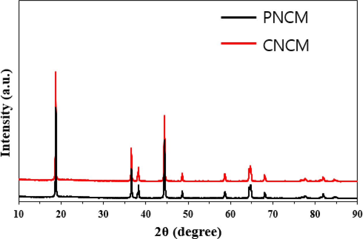
Fig. 1 shows the XRD patterns of the PNCM and CNCM. All peaks indicate the layered hexagonal α-NaFeO2 structure (R-3m space group, JCPDS 82-1495). The significant splitting of (006)/(102) and (018)/(110) peaks means well-ordered layered structure with low disordering of the cation on the transition-metal sublattice [2, 5]. No peak shift is observed after CaCO3 coating. Therefore, we can infer that there is no difference between both samples. The result proves that the coating layer does not affect the lattice expansion/shrinkage. Rietveld refinements were carried out for both samples. The change in lattice parameters are not obvious (α : 2.8723, c : 14.1951 for PNCM and α : 2.8725, c : 14.1956 for CNCM), indicating that the NCM structure is not modified. It is well known that the (003)/(104) peak intensity is widely used to infer the cation mixing. The value of intensity ratio of (003)/(104) peak for both samples is above 1.2 (PCNM : 1.39 and CNCM :1.51), indicating excellent layered structures with less cation disordering [3, 7].
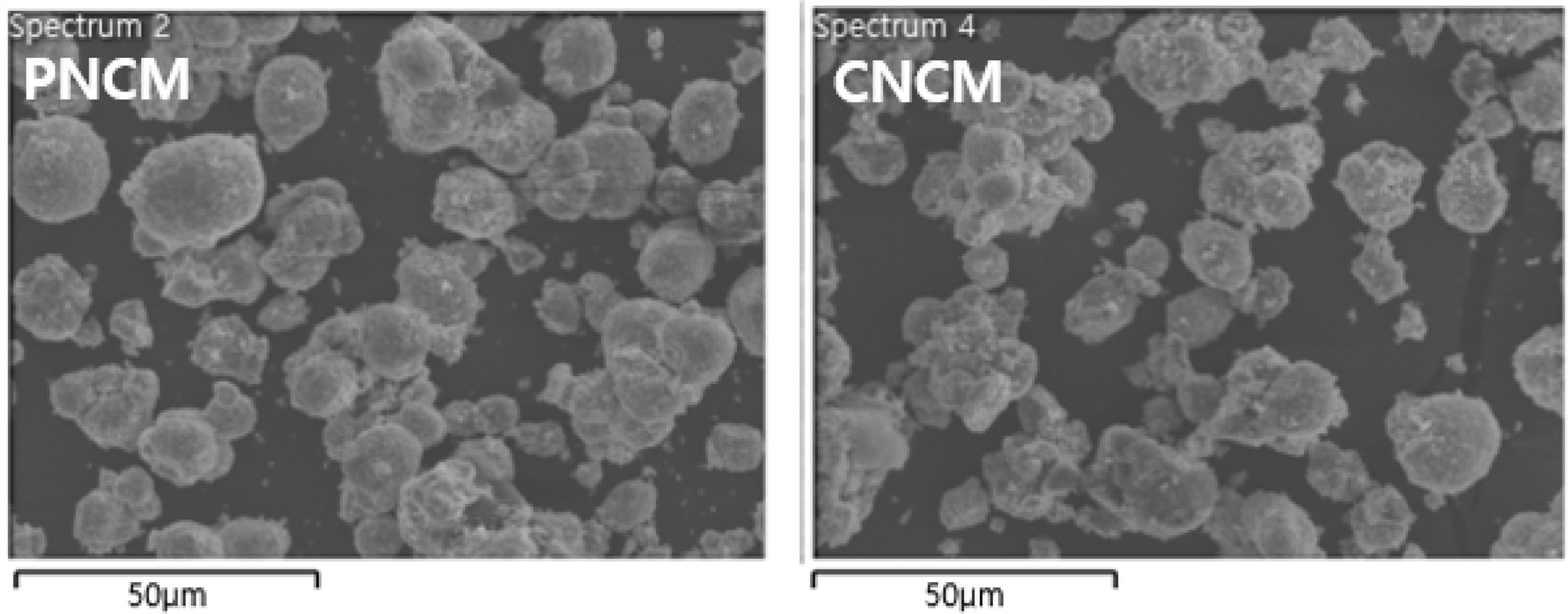
Fig. 2 shows the microstructures of the PNCM and CNCM. There is no obvious differences between both samples. The SEM images indicate that both samples exhibit the spherical granule morphology with average size of 10.5 μm, which is composed of numerous primary particles with average size ranged from 150 to 300 nm. This is typical shape of Ni-rich cathode powders. We can infer that coating does not change the shape and grain growth of PNCM. It is associated that Ni0.91Co0.06Mn0.03(OH)2 precursor act as a core and LiOH·H2O act as a nutrient, which is moves into the precursor. Both samples with pores shows high specific surface area, leading to excellent electrochemical per- formances via improved electrolyte wetting [4, 5].
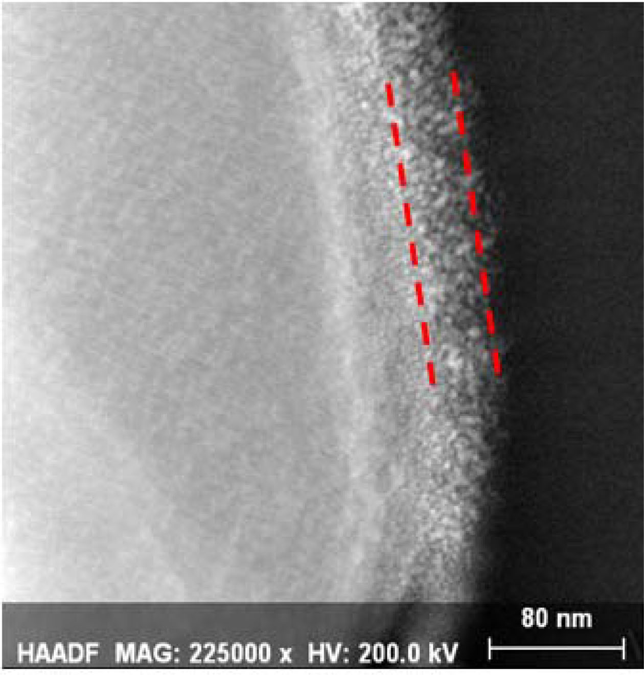
The STEM image of the PNCM and CNCM to confirm the coating layer on the surface, as shown in Fig. 3. The PNCM shows the good crystallinity with no amorphous later on the surface, which is the evidence of no coating layer. However, the CNCM exhibits clear amorphous coating layer on the surface of CNMC. The coating thickness is approximately 30.1 nm. Recently, our group reported that thin and uniform coating layer protect the Ni-rich cathode surface against hydrogen fluoride (HF) attack from electrolyte [7-9]. These struc- tural properties can affect the electrochemical perfor- mances, especially in regard to long-term cycle stability.
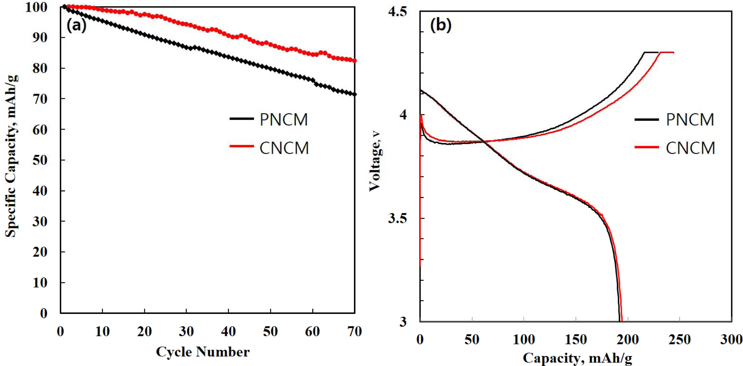
To measure the electrochemical performances, the PNCM and CNCM cathodes with very high mass loadings per area of active materials (approximately 14.5 mg/cm2) are prepared to meet practical cathode application. Fig. 4(a) delivers the long-term cycle performance of PNCM and CNCM. The initial discharge capacities of PNCM and CNCM are 195.6 and 197.3 mAh g-1, respectively, at 0.5 C (Fig. 4(b)). The initial discharge capacities of both samples are very slight difference. This is because the polarization of CNCM is decreased after proper amount of coating process. However, it can be seen that the capacity of the PNCM decreases relatively more rapidly compared to CNCM during the cycle test. It can be explained by an existence of coating layer. The coating layer plays a key role in suppressing the side reaction between liquid electrolyte and cathode [11]. In case of PNCM, i) the dissolution of transition metal ion, ii) structure collapse in the c direction and iii) formation of thick solid electrolyte interphase (SEI) layer, having low conductivity [12]. From these reasons, the fast capacity decay can be explained by micro-cracking, derived from irreversible volume change. This phenomenon enlarge the specific surface area, thus increasing unwanted side reaction. As a result, Li-ion kinetics are inhibited via generation of SEI layer in case of PNCM. The PNCM delivers inferior discharge capacity of 140.8 mAh g-1, and capacity retention of 72.6%. We can confirm that superior discharge capacity of 163.8 mAh g-1, and capacity retention of 83.1% for CNCM. This is because coating layer can act as a physical barrier against HF attack. Moreover, it can suppress the SEI layer growth, resulting in improvement of the electronic and ionic conductivity compared to PNCM [1-3]. Therefore, CNCM shows excellent elec- trochemical performances compared to PNCM. Such higher electrochemical performance was owed to the synergistic effects of fast and smooth electrochemical reaction kinetics and CaCO3 coating act as a barrier layer between the cathode and the electrolyte.
|
Fig. 1 XRD patterns of PNCM and CNCM. |
|
Fig. 2 FESEM images of PNCM and CNCM. |
|
Fig. 3 STEM image of CNCM. |
|
Fig. 4 (a) Cycle performance of PNCM and CNCM (b) initial charge-discharge curves of PNCM and CNCM. |
We successfully synthesized the PNCM and CNCM via coprecipitation method. Both samples show good layered structure with low cation mixing. Also, the similar morphologies (shape and average size) of both samples are observed. The CNCM delivers excellent initial discharge capacity and cycle stability compared to PNCM. It can be elucidated that CNCM has high electronic and ionic conductive coating layer. Moreover, It prevents adverse effects on PNCM. Therefore, we can conclude that the CaCO3 coating layer plays an important role in improving the electrochemical per- formances for Ni-rich NCM cathode.
- 1. Y. Lv, X. Cheng, W. Qiang, B. Huang, J. Power Sources. 450 (2020) 227718.
-

- 2. S.J. Sim, S.H. Lee, B.S. Jin, H.S. Kim, Sci. Rep. 9 (2019) 8952.
-
- 3. L. Tang, Y. Liu, H. Wei, C. Yan, Z.J. He, Y.J. Li, J.C. Zheng, J. Energy Chem. 55 (2021) 114-123.
-
- 4. Z. Peng, G. Yang, F. Li, Z. Zhu, Z. Liu, J. Alloy. Comp. 762 (2018) 827-834.
-
- 5. G. Hu, Y. Shi, J. Fan, Y. Cao, Z. Peng, Y. Zhang, F. Zhu, Q. Sun, Z. Xue, Y. Liu, K. Du, Electrochim. Acta 364 (2020) 137127.
-
- 6. S.H. Lee, B.S. Jin, H.S. Kim, Sci. Rep. 9 (2019) 17541.
-
- 7. S.H. Lee, H.S. Kim, B.S. Jin, J. Alloy. Comp. 803 (2019) 1032-1036.
-
- 8. J.W. Seok, J. Lee, T. Rodgers, D.H. Ko, J.H. Shim, Trans. Electr. Electron. Mater. 20 (2019) 548–553.
-
- 9. S.H. Lee, S. Lee, B.S. Jin, H.S. Kim, Sci. Rep. 9 (2019) 8901.
-
- 10. S.H. Lee, G.J. Park, S.J. Sim, B.S. Jin, H.S. Kim, J. Alloy. Comp. 791 (2019) 193-199.
-
- 11. S.H. Lee, K.Y. Kim, J.R. Yoon, NPG Asia Materials 12 (2020) 28.
-
- 12. S.H. Lee, S.J. Sim, B.S. Jin, H.S. Kim, Mater. Lett. 270 (2020) 127615.
-
 This Article
-
2021; 22(5): 517-520
Published on Oct 31, 2021
- 10.36410/jcpr.2021.22.5.517
- Received on Jan 18, 2021
- Revised on Apr 19, 2021
- Accepted on May 14, 2021
Services
Shared
Correspondence to
- Seung-Hwan Lee
-
Department of Advanced Materials Engineering, Daejeon University, Daejeon 34520, Republic of Korea
Tel : +82-42-280-2414 - E-mail: shlee@dju.kr
Clean-Energy Research Institute(CRI), Hanyang University, 222, Wangsimni-ro, Seongdong-gu, Seoul, 04763, Korea
E-mail: jcpr@hanyang.ac.kr