


- Study on effect of welding speed on friction stir welded aluminium metal matrix hybrid composite
P. Gopi Krishnana, B. Suresh Babub,*, S. Madhuc, S. J. Gowrishankard, C. Bibine, S. Saranf, S. Shree Ramf, A. R. Sri Harif and S.Vidyasagarf
aAssistant Professor, Department of Mechanical Engineering, Dr.N.G.P Institute of Technology, Coimbatore, Tamil Nadu, India
bAssistant Professor, Department of Mechanical Engineering, Sri Krishna College of Technology, Coimbatore, Tamil Nadu, India
cAssociate Professor, Department of Automobile Engineering, Saveetha School of Enginee ring, Saveetha Institute of Medical and Technical Sciences, Chennai, Tamil Nadu, India
dPG Student, Department of Mechanical Engineering, Sri Krishna College of Technology, Coimbatore, Tamil Nadu, India
eAssociate Professor, Department of Mechanical Engineering, RMK College of Engineering and Technology, Chennai, Tamil Nadu, India
fUG Students, Department of Mechanical Engineering, Sri Krishna College of Technology, Coimbatore, Tamil Nadu, IndiaThis article is an open access article distributed under the terms of the Creative Commons Attribution Non-Commercial License (http://creativecommons.org/licenses/by-nc/4.0) which permits unrestricted non-commercial use, distribution, and reproduction in any medium, provided the original work is properly cited.
The development of aluminum series matrix hybrid composites with ceramic reinforcements has recently caught the interest of new researchers. The addition of more than one or two reinforcements in aluminium alloy leads to the fabrication of the Aluminium Metal Matrix Hybrid Composite (AMMHC). The present investigation is aimed at the development of newly developed AMMHC followed by friction stir welding for obtaining the improved mechanical properties. The stir casted AA6063 with reinforcement of 5%, 10% and 15% wt. Silicon Carbide (SiC) and 10% wt. Boron Carbide (B4C) were fabricated by stir casting technique and the AMMHC with 10% each of SiC and B4C showed higher mechanical properties. Further the AMMHC are joined by friction stir welding (FSW) route. A prime experimental work has been tried out in the FSW process by varying welding speed (20, 30, 40, 50 and 60 mm/min). The effect of welding speed on AMMHCs were studied on macro and microstructural observations followed by micro hardness and ultimate tensile. Strength, in which 40 mm/min of welding speed gives better properties than other processing condition. The weldment reveals the better joint strength with the presence of fine particle dispersion in the microstructure.
Keywords: AA6063, Silicon Carbide, Boron Carbide, Stir cast, Friction Stir Welding
Composite is a multi-phase material composed of re- inforcements (fibres, particulates and flakes) embedded in a matrix material (polymers, metals, and ceramics). These constituents are united at the macroscopic level only and are not soluble in each other. The base materials are considered as a matrix, and other added materials are considered as reinforcement. In Metal Matrix Com- posites (MMCs), the matrix provides higher yield strength and modulus. It can also be plastically deformed and strengthened by a variety of thermal and mechanical treatments. The two most commonly used MMCs are based on Aluminium (Al) and Titanium (Ti). Ceramic Matrix Composites (CMCs) are used in very high tem- perature environments. These materials use ceramics as matrix and Silicon Carbide (SiC) and Boron Nitride (BN) as fiber reinforcements. Hybrid Metal Matrix Composites (HMMC) are described as metal matrix composites with at least two reinforcements. Based on the type of reinforcement, size and morphology, the HMMCs have been fabricated by different methods such as stir casting, squeeze casting, spray deposition, liquid infiltration, powder metallurgy, etc. The welding speed has a strong impact on productivity in streamlined production of friction stir welding of aluminium alloy sections.
Lee et al. [1] in his work found that the softened area is narrower for the higher welding speed than that for the lower welding speed. Thus, the tensile strength of as welded aluminium alloy has a proportional relationship with welding speed. Lomolino et al. [2] identified that higher welding speeds are associated with low heat inputs, which results in faster cooling rates of the welded joint. This can significantly reduce the extent of metallurgical transformations taking place during welding (such as re-precipitation and coarsening of precipitates) and hence the local strength of individual regions across the weld zone. Ying Chun Chen et al. [3] noted when the welding speed is lower and higher than a certain critical value, welding defects can be produced in the joints. Lima et al. [4] identified the fracture location of the joint gradually changes to the retreating side from the advancing side of the joint as the welding speed is gradually increased. Liu et al. [5] investigated the mechanical properties of friction stir welded AA1050 aluminium alloy and found that the tensile properties of all friction stir welded joints were lower than that of the base material. They observed that the width of the strained region and the maximum strain value decreased for the increased welding speed. Also observed that increasing the welding speed range from 200 to 600 mm/min increases the hardness values range from ~57 to 62 HV, to ~69 to 75 HV along the low hardness zones and this was attributed due to shortened dissolution time. Peel et al. [6] reported that by reducing the traverse speed, the nugget zone becomes wider, flatter and homogeneous. At higher traverse speeds, the original weld line was not fully broken, and voids were formed due to the poor consolidation of the weld interface because of lower heat inputs. Sakthivel et al. [7] studied the influence of welding speed on the tensile strength of friction stir welding aluminium alloys. They observed that decreasing the welding speed increases the ultimate strength of the friction stir welding joints. Salim et al. [8] demonstrated that the overall quality FSW joints is highly influenced by welding parameters (tool rotation and welding speeds). Faradonbeh et al. [9] found that FSW parameters had a major effect, when the tool travel speed was increased, the distribution of B4C particles was gradually uniform in the aluminium matrix. The effect of tool rotational speed on the peak temperature was determined to be greater than the tool travel speed. The attained data of tensile properties and microhardness tests showed that the tool travel speed had bilateral effect on the tensile strength Sutton et al. [10] studied the micro hardness of friction stir welded AA2024 and exhibited that the hardness of the nugget region during fast, medium and slow friction stir welding was in line with the base metal hardness. In all the welds, heat affected zone exhibits hardness minima. Lowest was observed in heat affected zone on the advancing side of the slow weld. An increase in the uniformity of hardness was found in the nugget with an increase in welding speed. The hardness values of the low hardness zones were dependent only on the welding speed. The density of precipitates tends to decrease with an increase in the welding speed. Balasubramanian [11] has studied the relationship between base metal properties and friction stir welding process parameters.
The relationship showed that the welding speed is proportional to the hardness of the aluminium alloys. At higher welding speeds in lower hardness aluminium alloys were fabricated without defects.
Gopi Krishnan et al. [12] fabricated AA7010-SiC-Al2O3 hybrid composite and obtained the better optimized FSW process parameters with the increased tensile strength using Genetic Algorithm. Suresh Babu et al. [13] tried out the different levels of welding speed, tool rotation speed and axial force to join the hybrid composite plates made of three ceramic reinfor- cements such as graphite, B4C and SiC. The weld characteristics showed improved physical and mechanical properties. Mohammed Sameer and Anil Kumar [14] investigated the effect of Alumina nanoparticles in the FSW of AA6082-T6 thin sheets. Number of weld pass was also added as one of the process parameters. The study confirmed the increase of the yield and ultimate tensile strength with the fine dispersed recrystallized particles. Ganjil et al. [15] compared the mechanical properties of friction stir processed Al–Zn–Mg–Cu alloy hybrid composite with the friction stir welded alloy. The results showed defective weldments with the alloys without surface composite. Jafari et al. [16] investigated on the residual stress distribution and the mechanical properties of friction stir welded dissimilar 7075-T6 and 6061-T6 aluminium alloys. The results showed the increase of tensile strength with the addition of Sio2 nanoparticles with the marginal decrease in the yield strength and residual stress.
On the whole the main objective is to fabricate the AA6063 with SiC and B4C hybrid composites by stir casting route followed by hybrid composites processed through friction stir welding route and to investigate the effect of welding speed on mechanical properties of hybrid composites which was not reported in the scientific community as on.
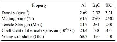
The proposed Al - SiC - B4C HMMC was produced by using a stir casting technique process. AA6063 alloy was used as a metal matrix, 10% wt of boron carbide with a size of 30 microns and 10% wt of silicon carbide with a size of 33 microns were used as a reinforcements. (K2TiF6) was used to enhancing the wettability of SiC and B4C with Alumium melt during the stir casting process. The value of chemical composition and the mechanical properties of AA6063 is shown in Table 1 and Table 2.
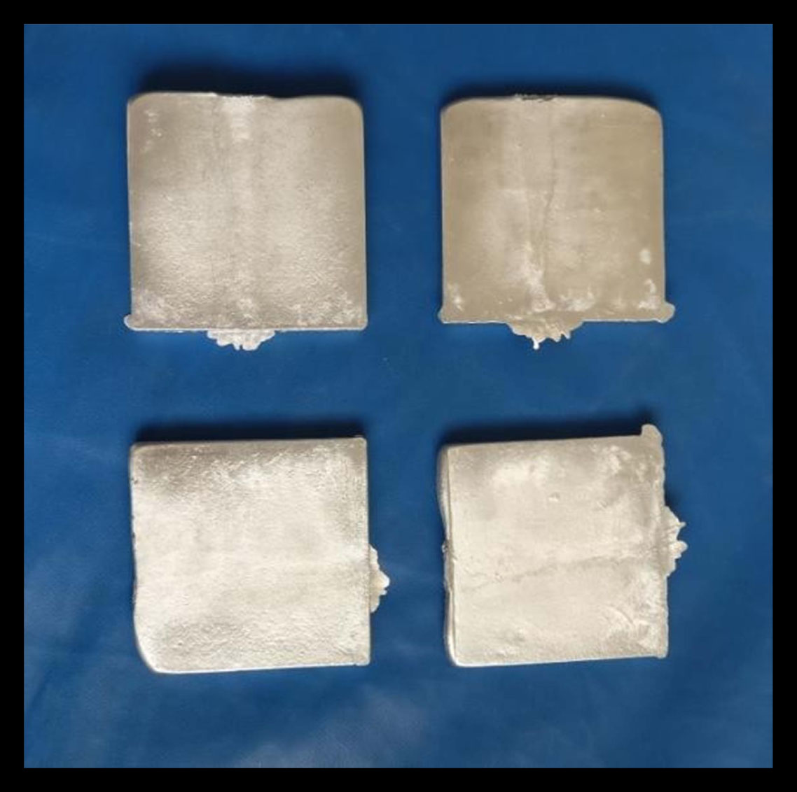
Aluminium alloy melted in crucible at 750oC using a furnace. Fig. 1 shows a typical stir casting set up. The melt was agitated with a help of a mechanical stirrer to form a vortex, then the mixtures of preheated SiC and B4C particles with K2TiF6 flux were added into the vortex at constant feed rate. Stir casting equipment incorporate the provision for shifting the melt into a mold. After the stirring process the molten mixture, were poured down into the already heated mold. The HMMCs having different weight % (5, 10 and 15) of SiC and 10 percentage weight of B4C were manufactured by the usual procedure. The maximum amount of B4C was limited up to 10% due to the formation of higher amount of slag on the melt surface which caused the inclusions in the trial castings. The manufactured HMMCs are shown in Fig. 1.
Fabrication of Hybrid Matrix Composites with silicon carbibe and boron carbide particulates by casting process is usually difficult because of the poor wetting between AA6063 with SiC and B4C agglomeration phenomena which result in weak mechanical properties. In the present work, Al 6063 aluminum alloy hybrid matrix composites reinforced with B4C and SiC particles were produced by stir casting route.
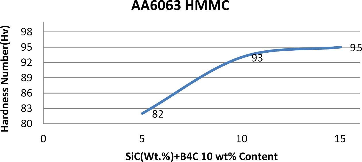
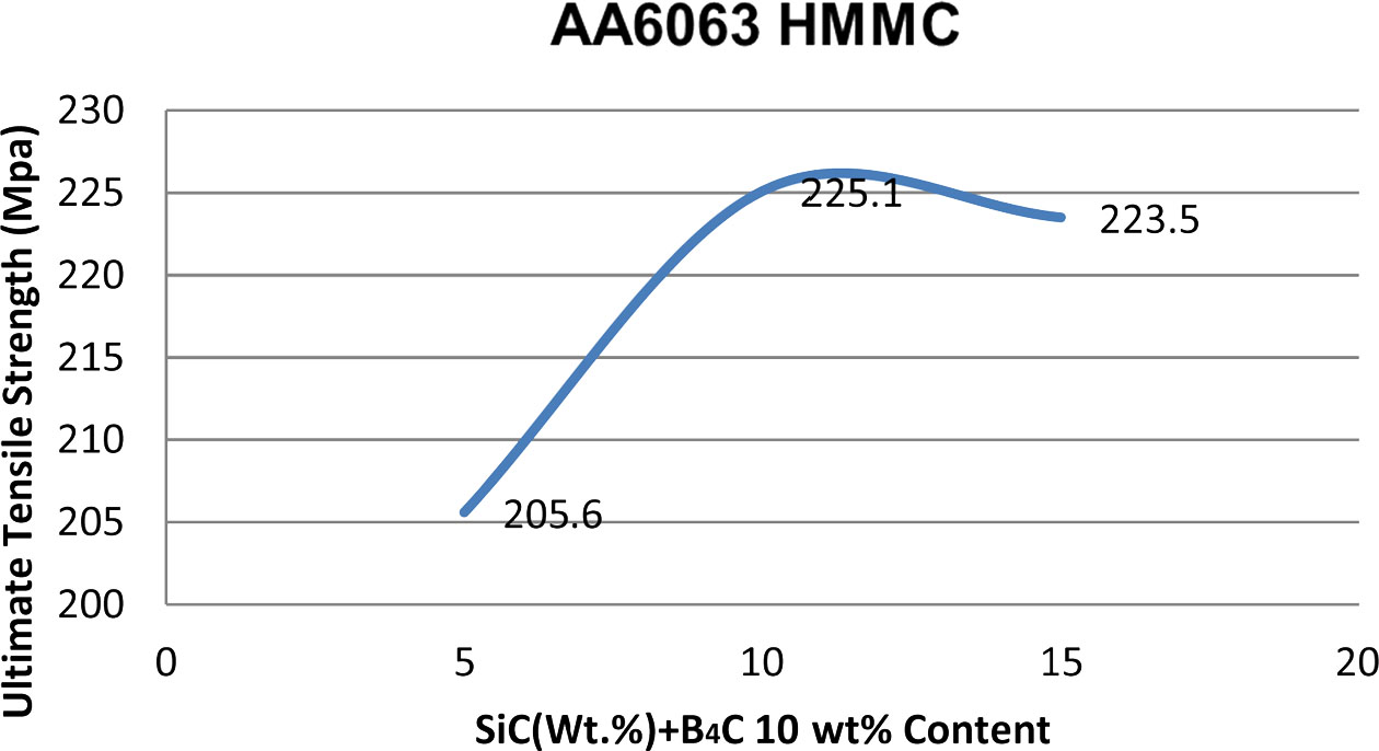
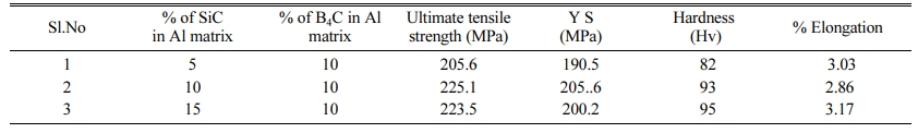
(K2TiF6) was used to increase the wettability between AA6063 hybrid metal matrix composites, which facilitates the incorporation of SiC and B4C particultes into molten aluminium. The HMMCs containing different weight % (5, 10 and 15) of SiC and 10% of B4C were manufactured. The microstructure and mechanical pro- perties of the manufactured metal matrix composites were analyzed. The good dispersion of B4C and SiC particles in the metal matrix was observed from the micrographs taken with OP and SEM. The mechanical properties like Brinell hardness and ultimate tensile strength were improved with the increase in various % weight of SiC and 10 % wt. of B4C particulates in the Aluminium hybrid matrix composite which is shown in the Fig. 2 and Fig. 3.
The mechanical properties of the fabricated metal matrix hybrid composites were analysed. The good dispersion of SiC and B4C particles in the matrix was observed visually during specimen preparation and also absents of porosity in the hybrid composite samples. The mechanical properties like Vickers micro hardness (93 HV) and ultimate tensile strength (225 MPa) were improved with the increasing of 10 wt% SiC and 10 wt% B4C particulates in the AA6063 hybrid composite than virgin AA6063. In further the prepared specimen with higher tensile strength AMMHC was taken for FSW process to prepare the joint.
|
Fig. 1 AA6063 with 5 wt% SiC and 5 wt% B4C hybrid composites |
|
Fig. 2 B4C and SiC Particulates on the Hardness of AA6063-B4C and SiC metal matrix composites. |
|
Fig. 3 B4C and SiC Particulates on UTS of AA6063-B4Cand SiC metal matrix composites. |

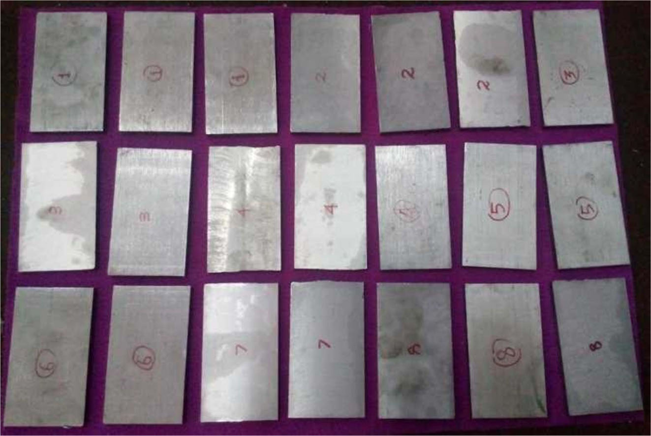
The manufactured stir cast plates were first cut into 6 mm thin plate by cutting them using a wire cut machine. Then the plates were cut to the required size of 100 ´ 50 ´ 6 mm and was shown in Fig. 4. Burrs were removed, and edges were prepared flat using grinding and emery polishing process. Before carrying out the experiments, all the specimens were cleaned to avoid any surface contaminations. To fabricate friction stir welding joints, the test plates were positioned and rigidly clamped to the backing plate using mechanical clamps which prevents the plates from vibrating during the process. Initial FSW trial operations were conducted by changing the range of the process parameters ie, the welding speed 20, 30, 40, 50 and 60 mm/min sequentially and remaining process parameters were kept constant (Tool rotation speed 1000 rpm and axial force of 10 KN) with hot tool steel as a tool material. This fixed process parameters and operating conditions were fixed based on literature survey findings and pilot experimental run. During the test heat input was determined by the following equation.

Where;
q = Heat input in kJ/mm, S = Welding speed in mm/min, F = Axial force (KN), N = Tool rotation speed (rpm), R = Tool pin radius (m), µ = Coefficient of the friction and η = Welding efficiency.
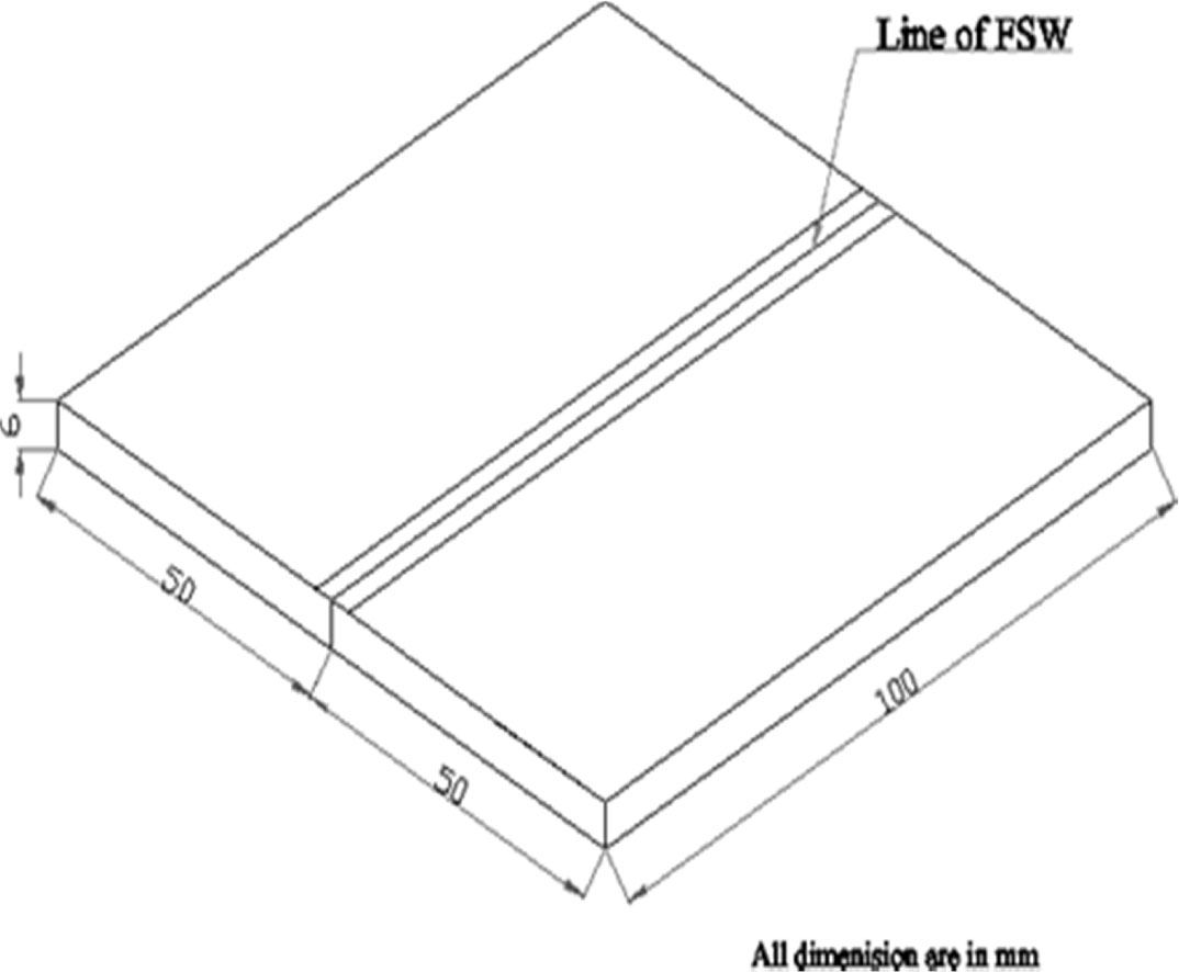
In FSW, for 20, 30, 40, 50 and 60 mm/min welding speed shows heat input of 1.20638, 0.9048, 0.7238 and 0.6032 KJ/mm respectively. It can be inferred that the heat input is directly proportional to the welding speed. If the welding speed increases, heat input decreases and vice versa. Finally, AA6063 with 10 wt% SiC and 10 wt% B4C hybrid composites were successfully joined all the five parametric conditions and it was taken for testing the metallurgical and mechanical properties by using standard procedure. The Fig. 5 represents dimensions of the specimen.
|
Fig. 4 Prepared AMMHC plates for FSW process. |
|
Fig. 5 Dimension of Specimen |
The AA6063 metal matrix hybrid composites manu- factured through stir casting technique and the joints were fabricated by varying the friction stir welding speed (20, 30, 40, 50 and 60 mm/min) and keeping tool rotation speed 1000 rpm and axial force 10 KN constant. The micro/macroscopic structure, micro hardness and tensile strength of the welded joints were examined and the results were discussed below.
Metallography analysis
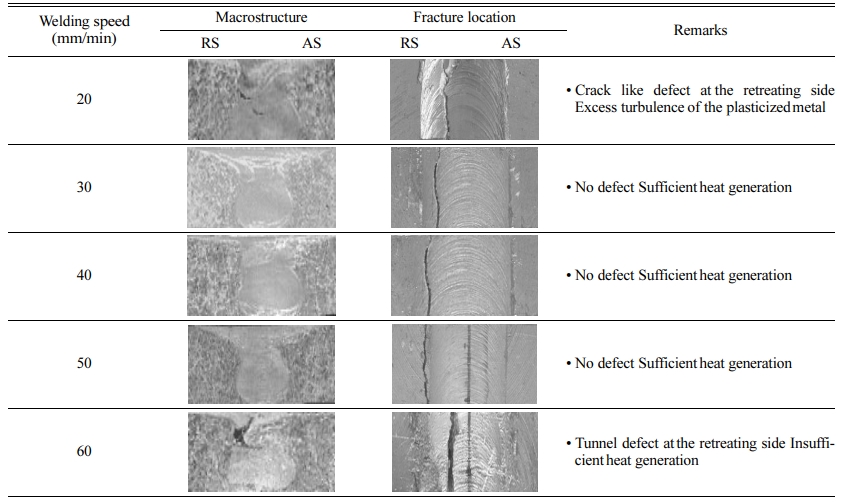
All the friction stir welded HMMC joints were analysed at low magnification (10X) using optical microscope to reveal the quality of weld region. The observations made from the macrostructure of the friction stir welded Al 6063 hybrid metal matrix composites joints were presented in Table 3. The joints fabricated using welding speed of 20 mm/min and 60 mm/min contain tunnel defect at the retreating side of the weld region and 30 mm/min, 40 mm/min and 50 mm/min are found to be free from macro level defects shown in the Table 4. From the macrostructure analysis, it can be inferred that the presence of defects in weld region deteriorated the tensile strength of the joints.
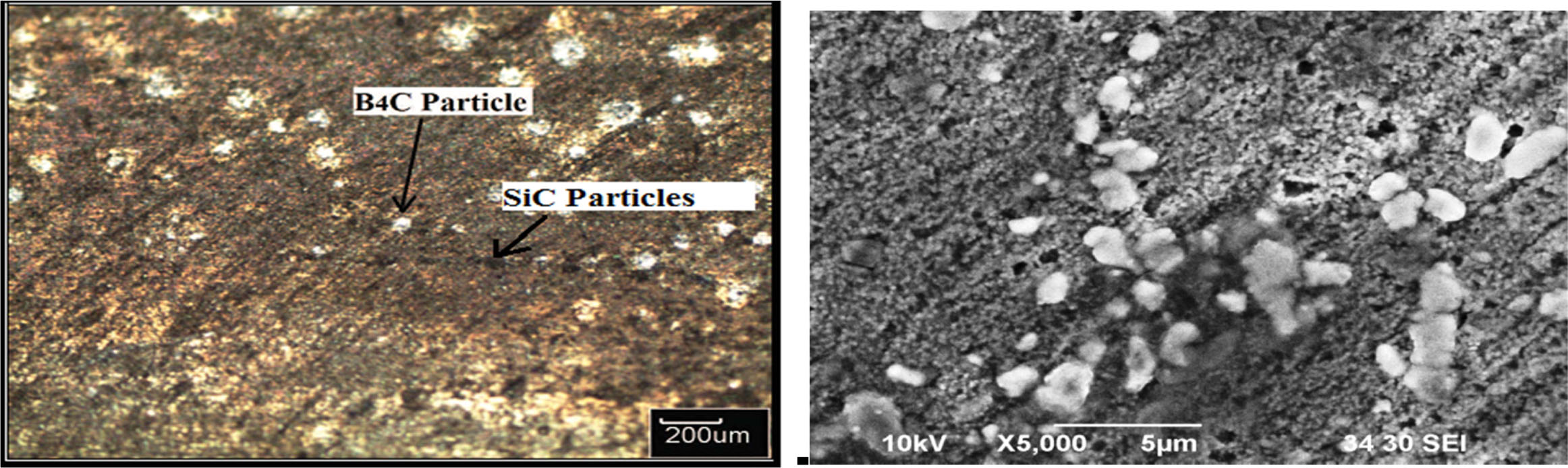
The fineness and the dispersion of silicon carbide and boron carbide particles mainly depend on the welding speed which in turn decides strength of the joints. If the welding speed increases, the heat input decreases, thus the size of the silicon carbide and boron carbide particulates are reduced and resulted in the growth of mechanical strength in the stir zone. The mechanical properties and fracture locations of the welded joints are to a large extent, dependent on the tool rotation speed and other welding parameters. If the joints are related with defects like pinhole, tunnel and cracks in the weld region, the joints failed at the defective area. The microstructure of weld region of the defect free joints was analysed using optical microscopy (OM) and scanning electron microscopy (SEM) were displayed in Fig. 6(a and b) From the micrographs and SEM, it can be inferred that the weld region of all the joints invariably contains uniformly distributed SiC and B4C particles. However, the size of the particles is different and it is found to be influenced by the welding speed. The weld region of Al 6063 hybrid metal matrix composites alloy fabricated using a welding speed of 40 mm/min shows very fine silicon carbide and boron carbide particles. The presence of very fine and uniformly distributed particles in the weld region may also be one of the reasons for higher tensile strength of these respective joints.
Micro hardness
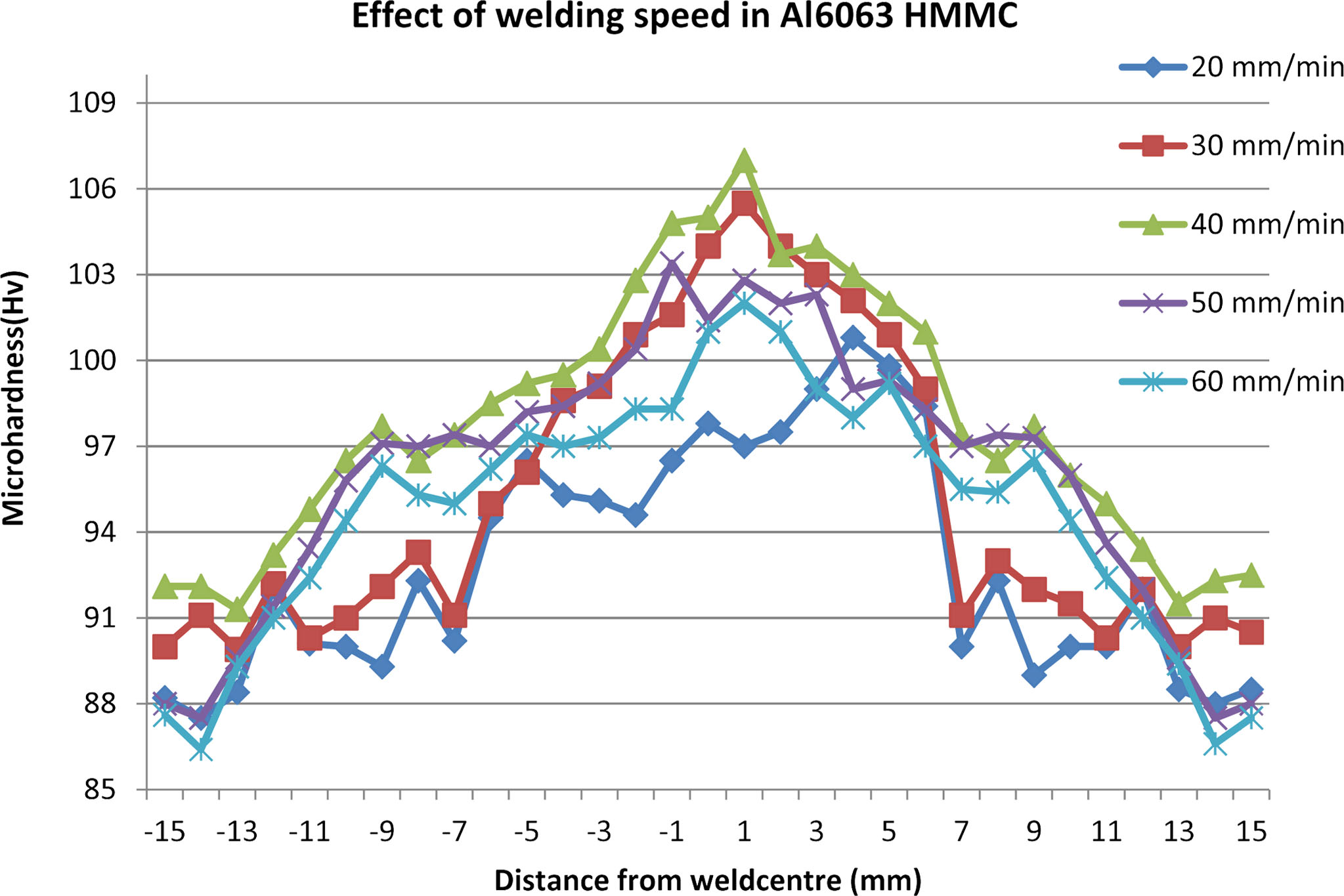
The micro hardness value was taken with 1 mm spacing between the weld zone of AMMHC. It is found that considerable raises in hardness was observed in the weld zone when compared to the base material AMMHC. Mainly thermal exposure during the FSW governs the hardness of the joints. Hardness drop was observed in the Thermo Mechanical Affected Zone (TMAZ), and Heat Affected Zone (HAZ) was due to the heat distribution during FSW process. The maximum micro hardness of 107 HV was observed at the nugget zone at 40 mm/min welding speed of the specimen. From the centre of the bead, the hardness is decreased gradually with increasing distance from the stir zone. The same trend was observed in all the cases of hardness profiles shown in the Fig. 7. From the micro hardness value of the nugget zone was noted to be in the range of 94.5 HV to 105.5 HV for all the five different welding speed samples (20-60 mm/min). In which, the lower value of welding speed 20, 30 m/min and higher welding speed of 50,60 mm/min shows deduction in micro hardness value. On the whole the maximum micro hardness value of 107 HV was recorded for the joint made using the welding speed of 40 mm/min due to presents of reinforcement in the matrix. Also absents of defects in the stir zone.
The hardness value in the weld nugget of AA6063 metal matrix hybrid composites was found to be higher than that base metal. The variation in micro hardness of the joints is due to changes in the heat input caused by frictional heat produced by rotating tool and subsequent alterations in the microstructure. When the welding speed is increased certain level, the hardness values initially rise and converge at higher welding speeds. This behaviour corresponds to the development of a more uniform temperature distribution within the weld region as the heat input is increased. It is also noticeable that the hardness value starts to decrease again at higher welding speeds. The hardness of the nugget zone were decreases with increasing welding speed.
Tensile strength
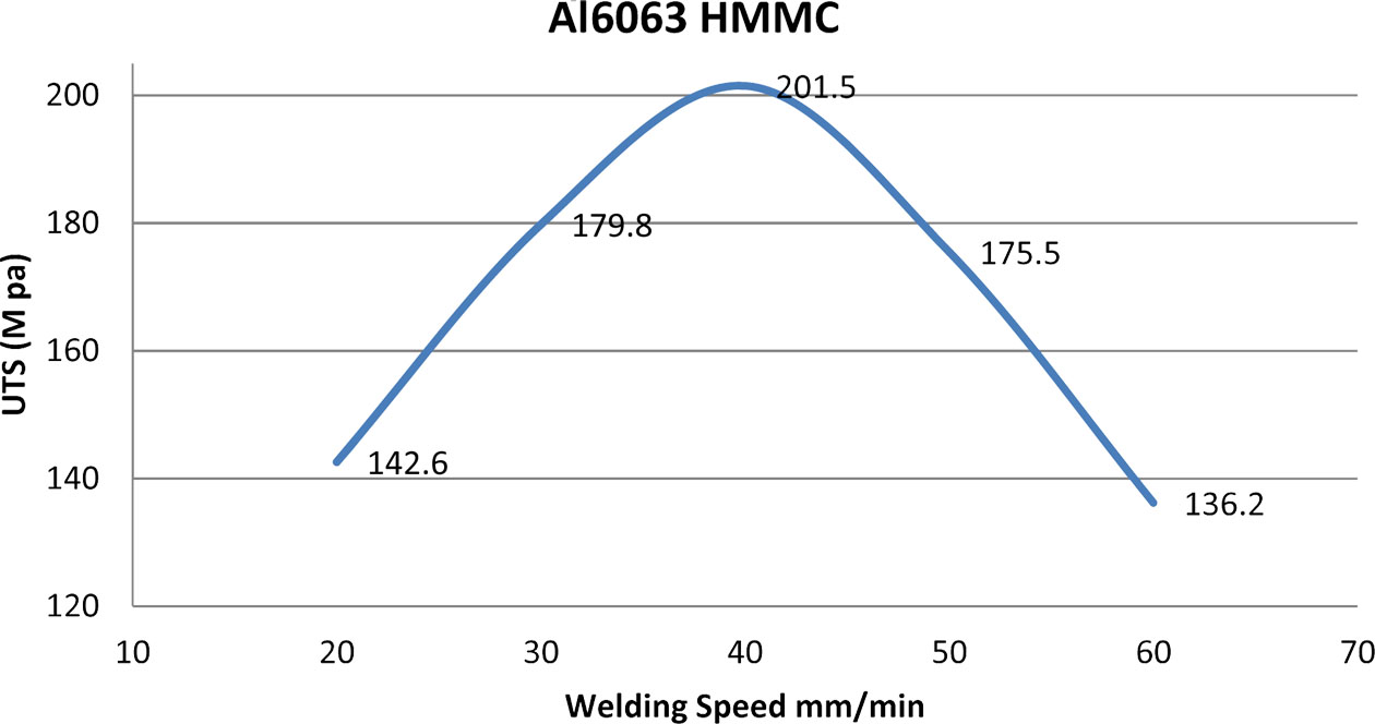
The outcome of welding speed on the tensile strength of FSW stir cast AMMHC is shown in the Fig. 8. Friction stir welding joints were manufactured by using the 20-60 mm/min welding speeds by execution and the other friction stir welding parameters kept constant. The joint manufactured a welding speed of 40 mm/min yielded higher tensile strength.
When the welding speed increases from 20 mm/min to 40 mm/min, the UTS of the FSW joints increases from the lower strength value and reaches maximum strength value before falling again at higher welding speed. At higher welding speed above 40 mm/min, the strength starts to reduce, was due to the insufficient heat input and plastic flow of material because of shorter exposure time in the SZ which results in pin hole defect in the SZ. The tensile strength variation of FSW on stir cast samples under different welding speed was shown in the Fig. 8.
The five welding speeds used to fabricate Al 6063 hybrid metal matrix composites, the joint fabricated using a welding speed of 40mm/min yielded higher tensile strength. The joints fabricated using the welding speeds lower and higher than these values, exhibited comparatively lower tensile strength.
Metallography structure observations showed that the FSW joints manufactured at higher welding speeds 60 mm/min contained tunnel and cavity defects in the weld portion and resulted in low tensile strength.
|
Fig. 6 Welding speed (40 mm/min) on weld region (a) Microstructure of AMMHC (b) SEM of AMMHC |
|
Fig. 7 Effect of tool rotation speed on micro hardness of weld zone. |
|
Fig. 8 Effect of tool rotation speed on tensile strength of weld zone |
In this work preparation of AA6063 metal matrix hybrid composites followed by FSW processing effects were analysed. The following conclusions were drawn from the above process.
• The matrix of AA6063 with 10 wt% SiC and 10 wt% B4C hybrid composites were successfully fabricated through stir casting route and obtained better hardness of 93 HV and tensile strength of 225.1 MPa.
• The FSW processing was done successfully by varying welding speed of 20, 30, 40, 50 and 60 mm/min and remaining parameters such as tool rotation speed 1000 rpm and axial load 10 KN kept constant for obtaining better joint.
• The effect of welding speed 40 mm/min on macro- structure and microstructure revealed the defect-free weld region with very fine, uniformly distributed SiC and B4C particles. weld region with very fine, uniformly distributed silicon carbide and boron carbide particles were presented in the stir zone.
• The effect of welding speed 40 mm/min on micro hardness and tensile strength of AMMHC fetched maximum hardness 107 HV and tensile strength 201.5 MPa of FSW joints.
• The optimization of friction stir welding process parameters of newly developed AMMHC may be further enhanced by considering more parameters for the effective usage in the industrial applications.
- 1. W.-B. Lee, Y.-M. Yeon, and S. Jung, Scr. Mater. 49[5] (2003) 423-428.
-

- 2. S. Lomolino, R. Tovo, and J.D. Santos, Inter. J. Fatig. 27[3] (2005) 305-316.
-
- 3. Y. Chen, H. Liu, and J. Feng, Mater. Sci. Eng. A 420[1] (2006) 21-25.
-
- 4. E.B.F. Lima, J. Wegener, A.R. Pyzalla, W. Reimers, C. Dalle Donne, G. Goerigk, T. Wroblewski, and T. Buslaps, Zeitschrift für Metallkunde 94[8] (2003) 908-915.
- 5. F. Liu and Z. Ma, Metal. Mater. Trans. A 39[10] (2008) 2378-2388.
-
- 6. M. Peel, A. Steuwer, M. Preuss, and P. Withers, Act. Mater. 51[16] (20030 4791-4801.
-
- 7. T. Sakthivel, G. Sengar, and J. Mukhopadhyay, Inter. J. Adv. Mfg. Tech. 43[5] (2009) 468-473.
-
- 8. O.S. Salih, N. Neate, H. Ou, and W. Sun, J. Mater. Pro. Tech. 275[1] (2020) 1163 -1166.
-
- 9. A.M. Faradonbeh, M. Shamanian, H. Edris, M. Paidar, and Y. Bozkurt, J. Mater. Eng. Perf. 27[2] (2018) 835-846.
-
- 10. M.A. Sutton, B. Yang, A.P. Reynolds, and J. Yan, Mater. Sci. Eng. A 364[1-2] (2004) 66-74.
-
- 11. V. Balasubramanian, A. Lakshminarayanan, Inter. J. Struct. Mater. Prop. 3[6] (2008) 837-853.
-
- 12. P. Gopi Krishnan, and K. Siva, High Temp. Mater. Process 20[3] (2016) 185-196.
-
- 13. B. Suresh Babu, G. Chandramohan, C. Boopathi, T. Pridhar, and R. Srinivasan, J. Ceram. Process. Res 19[1] (2018) 69-74.
- 14. S. Mohammed and A.K. Birru, Trans. Indian Ceram. Soc 78[3] (2019) 137-145.
-
- 15. N. Gangil, S. Maheshwari, A.N. Siddiquee, M.H. Abidi, M.A. El-Meligy, and J.A. Mohammed, J. Mater. Res. Technol 8[5] (2019) 3733-3740.
-
- 16. H. Jafari, H. Mansouri, and M. Honarpisheh, J. Manuf. Process 43 (2019) 145-153.
-
 This Article
-
2021; 22(5): 483-489
Published on Oct 31, 2021
- 10.36410/jcpr.2021.22.5.483
- Received on Apr 3, 2020
- Revised on May 15, 2021
- Accepted on Jun 25, 2021
Services
- Abstract
introduction
materials and method of hybrid composites preparation
friction stir welding procedure
results and discussions
conclusions
- References
- Full Text PDF
Shared
Correspondence to
- B. Suresh Babu
-
Assistant Professor, Department of Mechanical Engineering, Sri Krishna College of Technology, Coimbatore, Tamil Nadu, India
Tel : +91-9360556961 Fax: +91-422 2607162 - E-mail: babusrptc@yahoo.co.in
Clean-Energy Research Institute(CRI), Hanyang University, 222, Wangsimni-ro, Seongdong-gu, Seoul, 04763, Korea
E-mail: jcpr@hanyang.ac.kr