


- Effect of ZrC additives on the microstructure and hardness of ZrN-ZrSi2 composite
Z. I. Zakia,*, S. H. Alotaibib, M. Alsawata and B. A. Alhejjia
aDepartment of Chemistry, College of Science, Taif University, P.O. Box 11099, Taif 21944, Saudi Arabia
bDepartment of Chemistry, Turabah University College, Taif University, P.O. Box 11099, Taif 21944, Saudi ArabiaThis article is an open access article distributed under the terms of the Creative Commons Attribution Non-Commercial License (http://creativecommons.org/licenses/by-nc/4.0) which permits unrestricted non-commercial use, distribution, and reproduction in any medium, provided the original work is properly cited.
High-density zirconium nitride ZrN/ZrSi2 composite reinforced with different fractions of insitu formed ZrC were synthesized by dynamic-compaction combustion synthesis from Zr–Si3N4–C powder blends. The effect of ZrC fractions, compression loads, and delay time on the composite properties was investigated. ZrC additives were found to decrease the sample porosity and improve the sample hardness. Increasing the compression load greatly enhanced the sample hardness and reduced the sample porosity. The samples were characterized using XRD, SEM, hardness and porosity. The attained composite having 20 wt% ZrC was found to furnish a highly homogeneous microstructure with less than 1.0 vol open porosity and a maximum hardness value of 1308 HV achieved at 234 MPa compression load
Keywords: Ceramic composites, Zirconium nitride, Zirconium carbide, mechanical properties, Combustion synthesis
Zirconium nitride (ZrN) is considered an important candidate of the nitrides and having interesting com- binations of metallic, covalent and ionic bonding. It has many important characteristics such as its very high melting temperature (2,982 oC), moderate density (7.09 gcm-3) and high hardness (25 GPa). Other important properties include moderate thermal expansion (7.2× 10⁻⁶ K−1) and small thermal conductivity (21.9 Wm-1K-1) [14]. ZrN possesses a good superconductivity with a transition-temperature of 10 K and very small electrical resistance of 13.6 μΩ.cm at 300 K [5, 6].
ZrN fits with different industrial fields including decorative coatings of medical tools, hard coatings for cutting tools [7, 8], IR reflective materials [9]. Moreover, it has been recommended for windows as heat-mirrors [10] and a solar control coating [11]. It also utilized in electronics as a diffusion barrier in integrated circuits [12] and Josephson junction [13]. ZrN meets very important application in advanced nuclear power plants as inert matrix fuel (IMF) [5, 14, 15]. To be used as IMF, ZrN materials should have high mechanical and thermal characteristics and extraordinary anti-irradiation property [16]. ZrN has been tested as a nuclear fuel in mixed nitride, such as (Pu, Zr)N and (U, Zr)N. Mixed nitride fuels reduce the interaction between the fuel and the cladding and reveals a better swelling attitude [17].
Sintering of ZrN can be conducted via different sintering techniques such as hot isostatic pressing, hot pressing, and pressureless sintering [18]. Generally the densification of ZrN needs high sintering temperatures up to 2,000 oC, long times and/or application of high loads due to its low self diffusion coefficient, high melting temperature, and the presence of an oxide layer on the surfaces of ZrN grains [19, 20]. Pshenichnaya [21] prepared ZrN ceramics with 95% theoretical density in vacuum at 2,100 oC using fine ZrN powders (less than 1.0 µm particle size). High density ZrN has also been fabricated using spark plasma sintering methodology [22] starting from commercially ZrN powders. Spark plasma sintering technique with its lower temperature and time increased the theoretical density of ZrN to only 89.1% at 1,800 oC [23]. Moreover, attempts to reduce the sintering temperature of ZrN through forming liquid phase of low melting point metal such as Cr, Ni have been reported [24]. However the presence metal phase in boundaries of the ZrN grains may lead to reduced mechanical properties at high temperatures and a change in the electrical and thermal behaviours and anti-irradiation performance of ZrN-based composites. Both Zr and Ti additives were also reported to assist the ZrN sintering process. ZrN containing about 20 mol % Ti or Zr achieved more than 98% relative densities through hot pressing at 1,700 oC compared to about 2,000 oC for sintering of pure ZrN [20]. Producing sub-stoichiometric ZrN1−x ceramics was reported to accelerated sintering process [20]. Petrykina and Shvedova [25] showed that 99% TD sub-stoichiometric ZrN0.95 ceramics could be obtained without sintering aids by hot pressing for only 5 min at 2,500 oC under 45 MPa.
Improving the sintering behaviour of ceramic materials could be also established using ceramic sintering aides such as, SiC, ZrSi2, Si3N4, AlN and MoSi2 [26, 28]. Through the formation of liquid phases, ceramic sintering aids can generate fine microstructures at relatively lower sintering temperatures. ZrSi2 is commonly used as sintering aid for ZrB2 [26, 28-31]. Fully dense ZrB2-based composites containing 20 vol% ZrSi2 was produced at 1,650 oC and 1.0 h under vacuum of 7.0 × 10⁻³ Pa [29]. A mixture of SiC and ZrSi2 has been described as an effective sintering aid for ZrB2 ceramics [28, 32, 33]. By hot pressing and using only 5 wt% zirconium silicide and 5 wt% SiC platelet, Mingfu Wang et al. synthesized a nearly fully dense zirconium diboride ceramics at 1,800 oC for 1.0 h in argon atmosphere [28].
In addition to its applications in the field of ultra-high temperature ceramics, ZrC is frequently used as additives to ceramic composite in order to facilitate its sintering behaviour, and to produce better microstructure and enhanced mechanical properties [34]. Changchun stated that the addition of 3 wt% of nano-powder ZrC as a sintering aid suppressed the grain growth of WC, increased the theoretical density and Vickers hardness to 98.6% and 1800 HV10 respectively [35]. ZrC was also used as a binder during sintering of BN composite at 1,850 oC with the production of homogeneous microstructure [36]. Addition of 4.7 wt% ZrC to ZrB2–SiC composite sintered by SPS resulted in refined microstructure and enhanced mechanical properties [37]. Mixing of 20 mol % ZrC + 5 mol Cu with TaC increased the sample theoretical density from 86% to 97% and produced finer particle sizes and better microstructure [38].
Combustion synthesis is a well-known methodology and used frequently for synthesis of ceramic materials. It possesses the simplicity, time and energy savings in addition to the capability for in-situ synthesis and sintering of different types of matrices and reinforcements [39, 40]. To the best of our knowledge, synthesis of high density ZrN/ZrSi2 composite reinforced with ZrC by using combustion synthesis technique was not mentioned in the literature. In this work ZrC will be developed in situ and be used as a sintering aid and as a reinforce- ment of the ZrN-ZrSi2 composite. Therefore the current work was dedicated to study the effect of in-situ synthesized ZrC from Zr and C on the microstructure, mechanical and physical properties of ZrN-ZrSi2 com- posite by using combustion synthesis-dynamic com- paction methodology [41]. The technical parameters controlling the synthesis process such as ZrC additions, compression loads, and delay time were studied.
Materials
The materials used in this study were zirconium metal powder Zr (Riedel, USA, 98.0% purity, mean particle size 14.3 µm), graphite powder C (Sigma-Aldrich, 99% purity, mean particle size 19.6 µm), silicon nitride Si3N4 powder (Atlantic comp., USA, 99.0% purity, 1.45 µm).
Method
Reaction (1) was used to calculate the different weights of the reaction mixture.

Different weight fractions of ZrC were studied; 10, 20 and 30 wt% which corresponded to 1.38, 3.11 and 5.33 moles respectively. The calculated amounts of Zr, Si3N4 and C were mixed in a mortar agate for 7 min. The reactant mixtures were transferred to a steel die and compacted at 60 MPa into green cylindrical shapes (1.20 cm diameter and 1.0 cm height) by using hydraulic pressing. The compact was then encircled by a resistor coil and sited inside a steel mold (f 5 cm × 10 cm). The steel mold was filled to its half with sand powders. A motorized hydrolytic press was used to apply the required compression load during the reaction. The resistor coil was used to raise the sample temperature to the ignition point. The temperature of the compact was monitored using Type C thermocouple [42].
Characterization
Identification of different phases of powdered samples was carried out using X-ray diffractometer (D8 Advanced Bruker AXS, GMbH, karlsruhe, Germany). Diagnosis of microstructures was conducted by using Scanning Electron Microscope SEM (JSM-5410, JEOL, Tokyo, Japan). Before SEM examinations, the different samples were mounted, polished and coated with gold. LV 800 AT Digital Display Microhardness Tester was used to measure the samples’ hardness under 3.0 kgf load for 10 s.The open porosity and apparent densities of the different samples were determined by Archimedes’ immersion method [43, 44].
Thermodynamics study of the ZrN-ZrSi2-ZrC system
Thermodynamic calculations were performed for reaction (1) using eq. (2) and eq. (3). From eq. (2), Q, the heat required raising the temperature of the reactants from room temperature 298 K to the ignition temperature Tig, is derived. The adiabatic temperatures, the molten fractions of each phase as well as the total liquid phase are calculated at the measured ignition temperatures using equation (3). The calculations are based on the thermodynamic data reported by Ihsan et al. [45] and are carried out using Wolfram Mathematica 9.0 software.
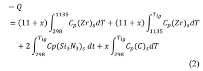
Where DHTig is the enthalpy of reaction (1) at the ignition temperature, Tad is the adiabatic temperature, Cp is the specific heat capacity of every component and ΔHf is the enthalpy of fusion. α and b are the molten fractions of ZrN and ZrSi2 respectively from which the total liquid phase is calculated. Solution of this equation in an iterative manner gives Tad, α and b.
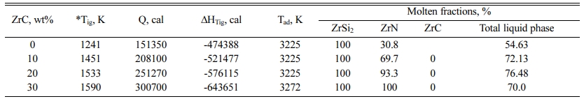
Reaction (1) is a highly exothermic one with enthalpy change at room temperature, DH298, of -467.34, -532.24.8, -613.63.0, -718.09 kcal in case of 0, 10, 20 and 30 wt% ZrC respectively. The energy released from the reaction is utilized in completing the reaction in a self-sustaining manner without the need of other energy resources. The measured ignition temperatures of the different samples have different values depending on the ZrC content as given in Table 1.
Generally, the calculated adiabatic combustion tem- perature (3,225 K) at the measured ignition temperatures equals to the melting point of ZrN phase (3,225 K) and exceeds that of ZrSi2 phase (1,893 K) and lies below the melting point of ZrC phase (3,805 K). Accordingly, thermodynamic calculations expect that the full amount of ZrSi2 phase should be liberated in the molten state and that the entire amount of ZrC phase will be developed in the solid state. On the other hand, some fractions of ZrN phase will be in the liquid phase while the rest will be generated in the solid phase except at 30 wt ZrC, where the Tad have exceeded 3,225 and the full amount of ZrN will be developed in the molten state. In another words, the enthalpy of reaction and the heat given to the system at 30 wt% ZrC is enough to raise the system temperature to the melting point of ZrN, melt the entire amounts of ZrN and heat the product to 3,272 K.
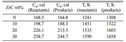
Detailed thermodynamic calculations are carried out in order to follow the different physical changes of the product due to the heat given to the reactants and the heat released during the reaction. 20 wt% ZrC-sample is chosen as an illustrative example. In case of 20 wt% ZrC (3.11 moles), heating the reactants to the ignition temperature (1,533 K) provides the system with 251,270 cal while the reaction itself supplies the system with 576,115 cal with a total heat content of 827,385 cal. Based on the adiabatic conditions, the reaction product should retain the same amount of heat (251,270 cal) that given to the reactants. The adiabatic calculation using 251,270 cal shows that the product temperature (1,603 K) has exceeded the reactant temperature (1,533 K) as shown in the Table 2. The reason for that is the difference in the heat capacity values of the reactants and products. The heat capacity of the product is less than that of the reactants which causes a logical increase of the product temperature, Table 2. Another reason is the phase transformation of zirconium content of the reactant occurs at 1,135 K. This requires 961 cal per mol of zirconium with a total of 13,559 out of 251,270 cal. This amount of heat will also contribute to a decrease of the reactants’ temperature than that of the products.
The product temperature will then increase from 1,603 K to 1,893 K, the melting point of ZrSi2, with consuming 63,324 cal. The product temperature remains unchanged at the melting point of zirconium silicide until it is totally converted to the liquid phase with the expending of 56,100 cal. The temperature of the product will start to increase again to the melting point of ZrN (3,225 K) with utilizing of 336,538 cal. The product temperature should remain stable at 3,225 K until the entire amount of ZrN phase is melt. The rest of the heat content of the system (120,153 cal) is only enough to melt 93.3 wt% of ZrN.
Effect of ZrC content of ZrN/ZrSi2 composite
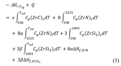
Different weight ratios of ZrC (0, 5, 10 and 20 wt%) were used in this study to improve ZrN/ZrSi2 composite's microstructure and mechanical properties. First of all, it should be stated that ZrC is developed during the combustion process due to a chemical reaction between Zr and C that was included in reaction (1). XRD of the samples reinforced with 0, 20 and 30 wt% ZrC pressed at 234 MPa are illustrated in Fig. 1. The main phases of the composite ZrN, ZrC and ZrSi2 were appeared in the diffraction pattern of the samples. However, ZrN and ZrC phases’ patterns were overlap and indistinguishable from each other. However, the un-appearance of free Zr or graphite phases in the XRD pattern is a good evidence for the formation of ZrC. On the other hand, the appearance of residual graphite only in case 30 wt% ZrC sample is also a good indication for the formation ZrC phase in lower ZrC-content samples. Another phenomenon is the increase of the intensity of ZrN and ZrSi2 lines in the XRD diagram in case of the presence of ZrC due to of the overlap between the ZrC pattern and that of ZrN and ZrSi2 phases.
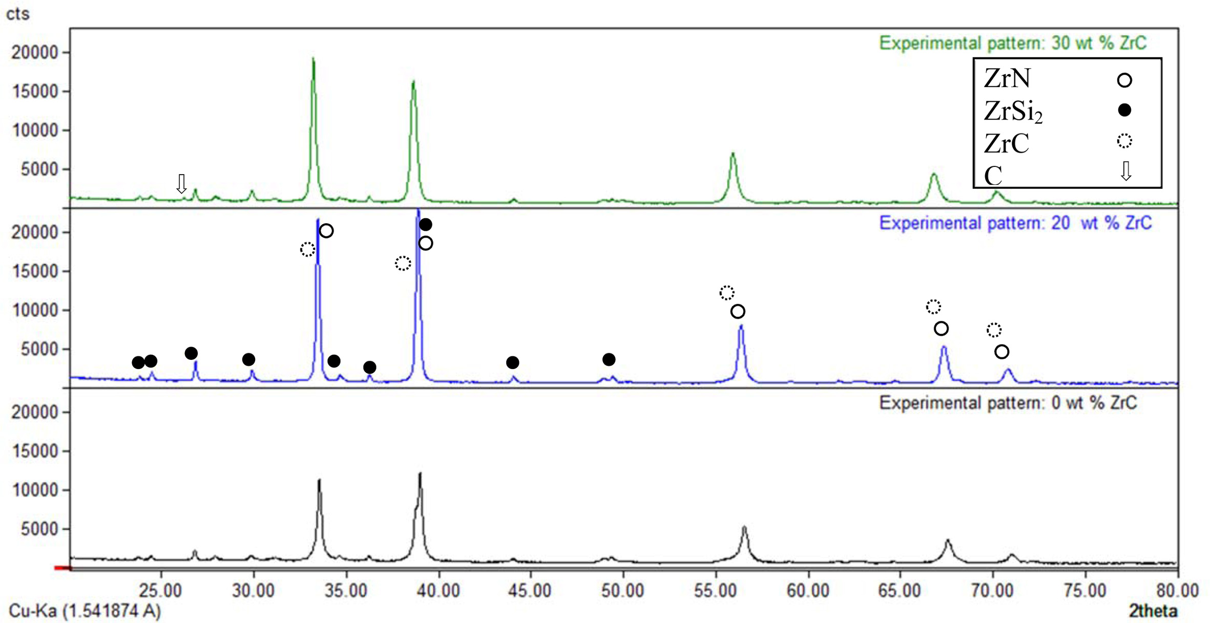
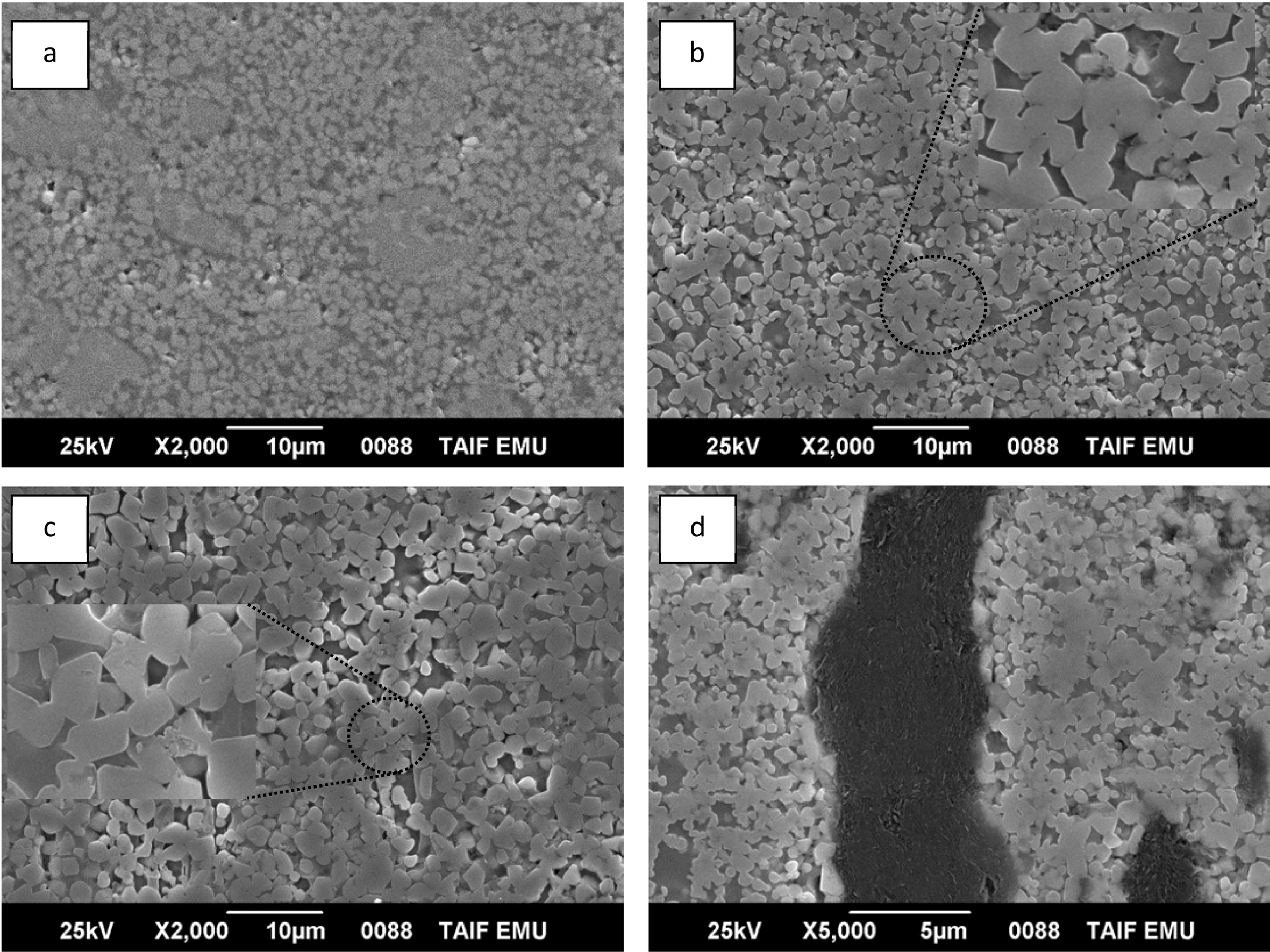
SEM images pictured for the samples having different ZrC weight ratios and prepared at 234 MPa are illustrated in Fig. 2. Generally, the samples showed fine and homogeneous microstructure that was almost pore-free. The sample also showed increased particle sizes of ZrN phase with increasing the ZrC content up to 20 wt%. This could be attributed to the sintering aid behaviour of ZrC to the ZrN phase. This is clearly shown by the SEM images where the sintering of ZrN grains through the neck formation is predominant. For 30 wt% ZrC-sample, agglomeration of graphite phase was observed in different areas which indicated incom- plete reaction between Zr and graphite at the experi- mental conditions. The mechanism of accumulation of graphite grains in such a big ensample is not clear.
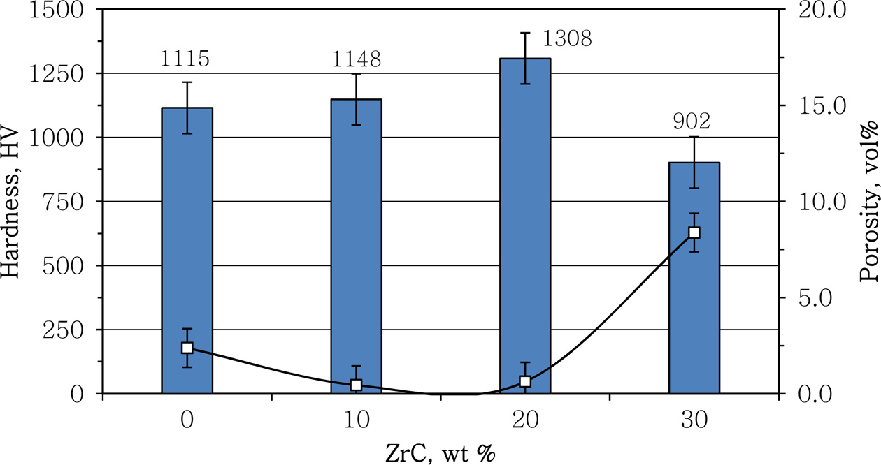
Porosity and hardness measurements the different samples compressed at 234 MPa are given in Fig. 3. The sample open porosity was decreased from 2.38 vol% in case of no additions to less than 1.0 vol% in case of 10 and 20 wt% ZrC-samples. On the other hand it went back to increase again to more than 8.0 vol% in case of 30 wt% ZrC-sample. This behaviour reflected the contribution of ZrC as a sintering aid to the ZrN/ZrSi2 composite up to 20 wt%. The increase of the porosity of 30 wt% ZrC-sample could be attributed to the incomplete reaction as proven from XRD diagram and SEM images of this sample.
The hardness behavior of the samples appeared to be completely consistent with the behavior of the porosity as shown from Fig. 3. The hardness slightly increased from 1,115 HV to 1148 with the addition of 10 wt% ZrC. However addition of 20 wt% ZrC significantly improved the hardness of the ZrN/ZrSi2 with more than 17% from 1,115 to 1,308 HV. This could attribute to the high hardness value of ZrC phase along with the effective sintering aiding behaviour of ZrC at that percentage. On the other hand the drop in the hardness value for 30 wt% ZrC sample was due to the inhomo- geneous microstructure and incomplete reaction at this percentage, Fig. 1 and Fig. 2.
Effect of compression load and delay time
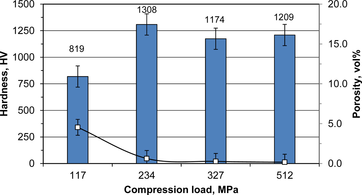
In a trial to improve the mechanical properties of the product, the compression load applied during the com- bustion process has been changed. As can be seen from Fig. 4, decreasing the compression load to 117 MPa lead to an increase in the open porosity to 4.54 vol% with a corresponding dramatic decrease in the sample hardness to 819 HV (~59% of its maximum value at 234 MPa). On the other hand, increasing the compression load more than 234 MPa has a bad impact on the sample hardness without any effect on the sample porosity. This behaviour could be attributed to some disturbance in the homogeneity of the microstructure of the sample. Usually increasing the compression load in the presence of a liquid phase more than the optimum one lead to a bigger grains precipitated from the liquid phase [41]. On the other hand, delaying the application of the compression load for only 2 seconds had bad impacts on the sample hardness and sample porosity. It decreased the sample hardness to 855 HV and increased the sample porosity to 5.8 vol%.
|
Fig. 1 XRD diagram of the combustion products having different wt% of ZrC pressed at 234 MPa. |
|
Fig. 2 SEM image of ZrN/ZrSi2 reinforced with different ZrC wt% prepared at 234 MPa: a) 0 wt% ZrC, b) 10 wt% ZrC, c) 20 wt% ZrC, d) 30 wt% ZrC. |
|
Fig. 3 Effect of ZrC content on products’ hardness (grey bars) and porosity (data points) |
|
Fig. 4 Effect of compression load on the hardness (bars) and porosity (data points) of products reinforced with 20 wt% ZrC. |
|
Table 2 Heat capacities at the ignition temperatures and the corresponding adiabatic temperatures of both the reactants and products |
During this work, insitu formed ZrC has been successfully used as reinforcement and sintering aid for ZrN/ZrSi2 composite via dynamic compaction combustion synthesis. The study revealed that the presence of ZrC significantly affected the hardness and porosity as well as the microstructure of the samples. It was found that at 234 MPa compression load, addition of 20 wt% of ZrC increased the sample hardness to 1,308 HV compared to 1,115 HV in case of no additives, with an increment of about 17%. The same proportion of ZrC reduced the open porosity of the sample from 2.34 to less than 1.0 vol% at the same compression load. Further increment in ZrC fractions led to incomplete reaction, inhomogeneous microstructure and increased porosity. In addition, decreasing or increasing the compression load beyond 234 MPa had also bad impact on the sample hardness, porosity and microstructure. Increasing the ZrN/ZrSi2 hardness more than 1,308 HV will be the target of the future work. Other additives such as yttria-stabilized zirconia 8YSZ with its high mechanical impact will be investigated.
This work was financially supported by Taif Researchers Supporting Project (TURSP-2020/42), Taif University, Taif, Saudi Arabia.
The authors report no declarations of interest.
- 1. C.G. Ribbing and A. Roos, in “Handbook of Optical Constants of Solids” (Academic Press, 1997) p.351-369.
-

- 2. H. Klostermann, F. Fietzke, T. Modes, and O. Zywitzki, Rev. Adv. Mater. Sci. 15[1] (2007) 33-37.
- 3. C. Hu, Y. Sakka, H. Tanaka, T. Nishimura, and S. Grasso, J. Alloys Compd. 494[1] (2010) 266-270.
-
- 4. R.W. Harrison and W.E. Lee, Adv. Appl. Ceram. 115[5] (2016) 294-307.
-
- 5. M. Streit, F. Ingold, M. Pouchon, L.J. Gauckler, and J.P. Ottaviani, J. Nucl. Mater. 319[1] (2003) 51-58.
-
- 6. J. Adachi, K. Kurosaki, M. Uno, and S. Yamanaka, J. Nucl. Mater. 358[2] (2006) 106-110.
-
- 7. H.E. Hintermann, Thin Solid Films 84[3] (1981) 215-243.
-
- 8. X.Y. Li, G.B. Li, F.J. Wang, T.C. Ma, D.Z. Yang, and Y.C. Zhu, Vacuum 43[5] (1992) 653-656.
-
- 9. M. Yoshitake, T. Y. T. Yotsuya, and S. O. S. Ogawa, Jpn. J. Appl. Phys. 31[12R] (1992) 4002.
-
- 10. 1A. Singh, P. Kuppusami, S. Khan, C. Sudha, R. Thirumurugesan, R. Ramaseshan, R. Divakar, E. Mohandas, and S. Dash, Appl. Surf. Sci. 280[17] (2013) 117-123.
-
- 11. 1K.E. Andersson, M. Veszelei, and A. Roos, Sol. Energy Mater. Sol. Cells 32[2] (1994) 199-212.
-
- 12. 1L. Krusin-Elbaum, M. Wittmer, C.Y. Ting and J.J. Cuomo, in “ZrN Diffusion Barrier in Aluminum Metallization Schemes1982” (Cambridge University Press, 1982) p.81.
-
- 13. 1K. Schwarz, A.R. Williams, J.J. Cuomo, J.H.E. Harper, Hentzell, and G.H. T, Phys. Rev. B 32[12] (1985) 8312-8316.
-
- 14. 1C.T. Walker and G. Nicolaou, J. Nucl. Mater. 218[2] (1995) 129-138.
-
- 15. B.D. Rogozkin, N.M. Stepennova, and A.A. Proshkin, At. Energ. 95[3] (2003) 624-636.
-
- 16. M.K. Meyer, R. Fielding, and J. Gan, J. Nucl. Mater. 371[1] (2007) 281-287.
-
- 17. W. Chubb, R.F. Hilbert, V.W. Storhok, and D.L. Keller, Mater. Sci. Eng. 9 (1972) 293-300.
-
- 18. B. Ma, Z. Gao, C. Su, X. Ren, G. Li, and Q. Zhu, Int. J. Appl. Ceram. Technol. 17[1] (2020) 175-183.
-
- 19. T. Tsuchida, M. Kawaguchi, and K. Kodaira, Solid State Ion. 101-103[1] (1997) 149-154.
-
- 20. Y. Tang, G.-J. Zhang, J.-X. Xue, X.-G. Wang, C.-M. Xu, and X. Huang, J. Eur. Ceram. Soc. 33[7] (2013) 1363-1371.
-
- 21. O.V. Pshenichnaya, M.A. Kuzenkova, and P.S. Kislyi, Sov. Powder. Metall. Met. Ceram. 14[12] (1975) 986-989.
-
- 22. J. Adachi, K. Kurosaki, M. Uno, and S. Yamanaka, J. Alloys Compd. 432[1] (2007) 7-10.
-
- 23. H. Muta, K. Kurosaki, M. Uno, and S. Yamanaka, J. Nucl. Mater. 389[1] (2009) 186-190.
-
- 24. F.F. Egorov and V.E. Matsera, Powder Metall. Met. Ceram. 37[11] (1998) 593-596.
-
- 25. R.Y. Petrykina and L.K. Shvedova, Sov. Powder. Metall. Met. Ceram. 11[4] (1972) 276-279.
-
- 26. S.-Q. Guo, Y. Kagawa, and T. Nishimura, J. Eur. Ceram. Soc. 29[4] (2009) 787-794.
-
- 27. S. Meng, H. Chen, J. Hu, and Z. Wang, Mater. Des. 32[1] (2011) 377-381.
-
- 28. M. Wang, C.-A. Wang, and X. Zhang, Mater. Des. 34[2] (2012) 293-297.
-
- 29. S.-Q. Guo, Y. Kagawa, T. Nishimura, and H. Tanaka, Scr. Mater. 58[7] (2008) 579-582.
-
- 30. O.N. Grigoriev, B.A. Galanov, V.A. Kotenko, S.M. Ivanov, A.V. Koroteev, and N.P. Brodnikovsky, J. Eur. Ceram. Soc. 30[11] (2010) 2173-2181.
-
- 31. G. Shao, X. Zhao, H. Wang, J. Chen, R. Zhang, B. Fan, H. Lu, H. Xu, and D. Chen, Int. J. Refract. Met. Hard Mater. 60[11] (2016) 104-107.
-
- 32. O.N. Grigoriev, B.A. Galanov, V.A. Lavrenko, A.D. Panasyuk, S.M. Ivanov, A.V. Koroteev, and K.G. Nickel, J. Eur. Ceram. Soc. 30[11] (2010) 2397-2405.
-
- 33. I.-Y. Ko, J.-H. Park, J.-K. Yoon, K.-S. Nam, and I.-J. Shon, Ceram. Int. 36[2] (2010) 817-820.
-
- 34. K.S. Camposa, G.F.B.L.e. Silvab, E.H.M. Nunesa, and L.V. Wander, J. Ceram. Process. Res. 15[6] (2014) 403-407.
- 35. C. Lv, X. Ren, C. Wang, and Z. Peng, Int. J. Appl. Ceram. Technol. 17[3] (2020) 932-940.
-
- 36. K.V. Slipchenko, D.A. Stratiichuk, V.Z. Turkevich, N.M. Bilyavyna, V.M. Bushlya, and J.E. Ståhl, Journal of Superhard Materials 42[4] (2020) 229-234.
-
- 37. M. Xiang, J. Gu, W. Ji, J. Xie, W. Wang, Y. Xiong, and Z. Fu, Ceram. Int. 44[7] (2018) 8417-8422.
-
- 38. L. Liu, G. Geng, W. Hai, Y. Chen, and L. Wu, Ceram. Int. 42[14] (2016) 16248-16254.
-
- 39. A. Masoudiana, M. Karbasib, F. SharifianJazia, and A. Saidib, J. Ceram. Process. Res. 14[4] (2013) 486-491.
- 40. C. Tawat, J. Ceram. Process. Res. 18[5] (2017) 389-393.
- 41. Z. Zaki, N. Mostafa, Y. Ahmed, E. Ewais, and M. Rashad, Int. J. Appl. Ceram. Technol. 13[4] (2016) 662-669.
-
- 42. Z.I. Zaki, N.Y. Mostafa, and M.M. Rashad, Ceram. Int. 38[6] (2012) 5231-5237.
-
- 43. ASTM C693-93 (2019), Standard Test Method for Density of Glass by Buoyancy, ASTM International, West Con- shohocken, PA, 2019, www.astm.org, p.1-3.
- 44. P. Mazón and P.N. De Aza, Ceram. Int. 44[1] (2018) 537-545.
-
- 45. I. Barin, O. Knacke, and O. Kubaschewski, in “Thermo- chemical properties of inorganic substances” (Springer Berlin Heidelberg, 1977) p.1851-1878.
-
 This Article
-
2021; 22(4): 455-460
Published on Aug 31, 2021
- 10.36410/jcpr.2021.22.4.455
- Received on Jan 21, 2021
- Revised on Apr 25, 2021
- Accepted on May 14, 2021
Services
- Abstract
introduction
experimental
results and discussion
conclusion
- Acknowledgements
- Conflict of Interest
- References
- Full Text PDF
Shared
Correspondence to
- Z. I. Zaki
-
Department of Chemistry, College of Science, Taif University, P.O. Box 11099, Taif 21944, Saudi Arabia
Tel : +966590019562 Fax: +9667272020 - E-mail: zakimohamed@tu.edu.sa
Clean-Energy Research Institute(CRI), Hanyang University, 222, Wangsimni-ro, Seongdong-gu, Seoul, 04763, Korea
E-mail: jcpr@hanyang.ac.kr