


- The bio-composites (Hydroxyapatite/High-density polyethylene) materials reinforced with Multi-walled carbon nanotubes for bone tissue repair
Ali A. Al-allaqa,b,*, Jenan S. Kashanc, Mohamed T. El-Wakadd and Ahmed M. Solimanb
aMinistry of Higher Education and Scientific Research, Office Reconstruction and Projects ,Baghdad, Iraq
bBiomedical Engineering Department ,Faculty of Engineering, Helwan University Cairo, Egypt
cBiomedical Engineering Department, University of Technology, Baghdad, Iraq
dFaculty of Engineering and Technology, Future University, Cairo, EgyptThis article is an open access article distributed under the terms of the Creative Commons Attribution Non-Commercial License (http://creativecommons.org/licenses/by-nc/4.0) which permits unrestricted non-commercial use, distribution, and reproduction in any medium, provided the original work is properly cited.
Due to the predominance diseases such as bone fracture, bone cancer, and osteoporosis Worldwide. There is a developing requirement for synthesizing biomaterials for bone repair or substitute due to the predominance of bone fracture, bone cancer, and osteoporosis. In this study, multi-wall carbon nanotubes (MWCNT) of (0.6%, 1%, 1.4%, 2%) wt.% and High-density polyethylene HDPE (60) wt.% were incorporated into hydroxyapatite (40) wt.% to form biocomposite using hot-press techniques. These samples were characterized by XRD, Field Emission scanning electron microscope (FESEM), Atomic force microscopy (AFM), mechanical properties with tensile strength and hardness test. Homogeneous, better distribution of the fibrous network and microstructure arrangements were among the most prominent characteristics obtained through XRD, FESEM, and AFM examinations. The result showed improved approximately (3.1 times) compared with pure sample (without addition MWCNT) in the tensile test. Also, the microhardness improves approximate 24% compared to pure samples HA/ HDPE. Based on the experimental results, the synthesis HA/ HDPE/MWCNT bio-composites prepared to have excellent characteristics that make them suitable application as a substitute material for bone repair
Keywords: Bone tissue engineering, Hydroxyapatite, Hot-pressing technique, Biomaterials, Nanocomposite, Brazilian test, Bone scaffold
Bone tissue is arranged in a hierarchical structure. The sub-microstructure contains lamellae consisting of layers of fibers of mineralized collagen organized in a planar form. In collagen fibers, collagen fibrils are made of collagen molecules and hydroxyapatite (HA) mineral crystals [1]. Bone is a dynamic type of biological tissue that can continuously reconstruct by two processes, modelling and remodeling, to keep it functional. The bone tissue is responsible for numerous vital purposes in the body, such as contributing to mineral equilibrium, being the primary section of hematopoiesis and contri- buting structural support for body and soft tissues [2]. Osteoblasts have played an important role in skeletal growth regarding many types of local, systemic, and mechanical stimuli that help mineralization while they organize bone remodeling. This cell obtained from pluripotent mesenchymal stem cells (MSCs), they develop along a particular lineage to become extremely functional synthetic cells [3]. Bone grafting is a surgical operation that substitutes missing bone in extremely complex fractures with vital health risks to the patient or fails in the healing process. This treatment method is used in numerous dysfunction cases, including osseous defects from trauma, delayed fusion or non-fusion of fractures, infection, congenital pseudoarthrosis, tumors, and reconstruction facial surgery [4]. The main dis- advantage of bone grafting is that the harvest from the place is often extremely painful, especially after the operation and has a vital risk of increasing complications such as infection, hematoma, nerve injury, in some cases leaving an area of numbness near in harvest region and donor risks [5]. Biomaterial, an impressive field, strong development over its approximate half-century presence, contains parts of materials science, medicine, chemistry, and biology field [6]. After im- plantation, bone biomaterials serve as a medium for the interaction and contact of bone implants with the enclosing tissues/cells. So, bone the biomaterial choice is an important step in the formation of ideal bone implants. Bone implants should possess mechanical characteristics that match the natural bone in the injury site and newly formed tissues through bone repair stages. Otherwise, failure may occur in bone repair inside of the human body. The mechanical properties of selective bone biomaterials are deemed one of the most significant selection criteria [7]. Many biomaterials such as ceramics, synthetic polymers, natural polymers, metals and their composites have been widely applied in biomedical applications. The selective of material pattern performs a significant function in the properties of bone scaffolds.
The apatite layer covers the composites' bioinert polymer area, due to the HA exposed to the physiological environment (simulated body fluid), which improved the bioactive surface area to function as nucleation sites to induce the apatite layer. It means that polymers' surfaces with HA bioactive composites are compatible with bone growth with the apatite layer giving an interaction between the composites and tissues [8]. The bioactive feature encourages the formation of the HA layer, which attracts protein to which cells adhere or bind, differentiate and proliferate, leading to bio mineralization and matrix production for new bone formation [9].
Many researchers have recently investigated modifi- cations of the biocomposite composition and structure by modified or novel prepare methods aimed to improve the mechanical features and attempt to access characteristics closer to natural bone. The first idea of compatible implant material for bone replacement by prepared bio-composites material from polyethylene and hydroxyapatite powder was presented by the author [10]. The applications of HA are limited because of as bioceramic feature, so it does not have the mechanical strength to enable it to support long load-bearing applications [11, 12]. This weakness in the characteristics of HA has been led to the interest of many researchers for improving its characteristics. One of the investigations approaches to overcome this weakness is to fabricate composites by combining reinforcing phases, including polymers such as [13, 14], metals [15] and carbon nanotubes [16-18]. As reported in [19, 20], the polyethylene -hydroxyapatite biocomposite with hydroxyapatite content within (40% volume fraction values) exhibits natural bone features such as Young's modulus, bioactivity, and ductility.
Several investigations on CNT reinforced ceramic/ metal/ polymer composites have successfully exhibited its ability to improve the structural and biological properties, such as elastic modulus, strength, wear resistance, fracture toughness also accelerated bone growth (in-vitro) and enhanced differentiation and proliferation of osteoblast (in-vitro) [21]. The CNT has a surface area and surface roughness similar to collagen fibers in the extracellular matrix, which can greatly improve cell attachment [17]. To the best of our knowledge, there has been no experimental investigation at mixing (HA, HDPE, MWCNT) together by using the hot-press technique to form bio-composites material promising for bone substitute. This work aims to investigate the enhancement by adding (0.6, 1, 1.4, 2) % weights of MWCNT into hybrid nano bio-composite (40%HA, 60%HDPE) on the microstructure, morphology and mechanical properties.
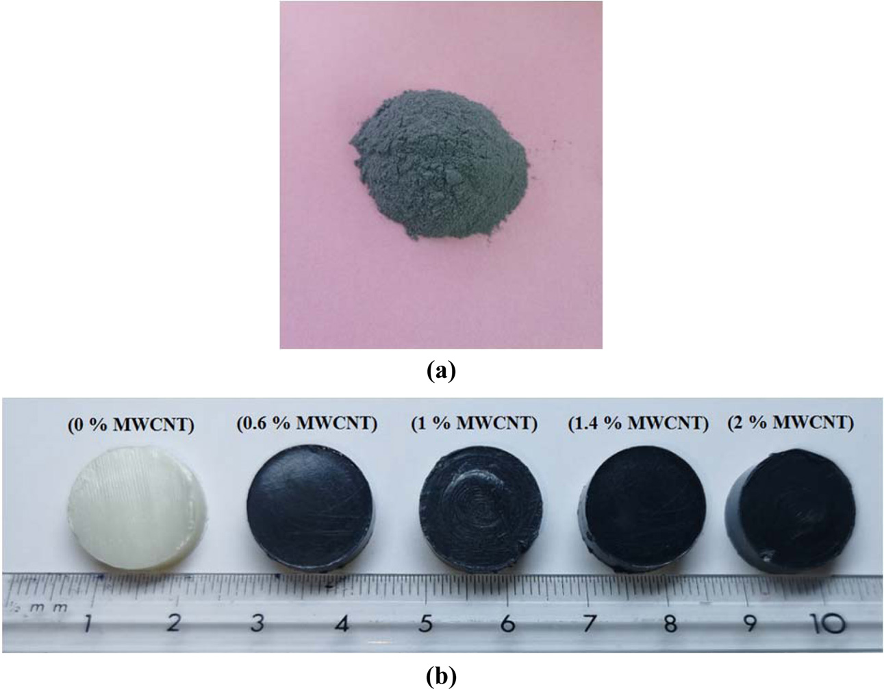
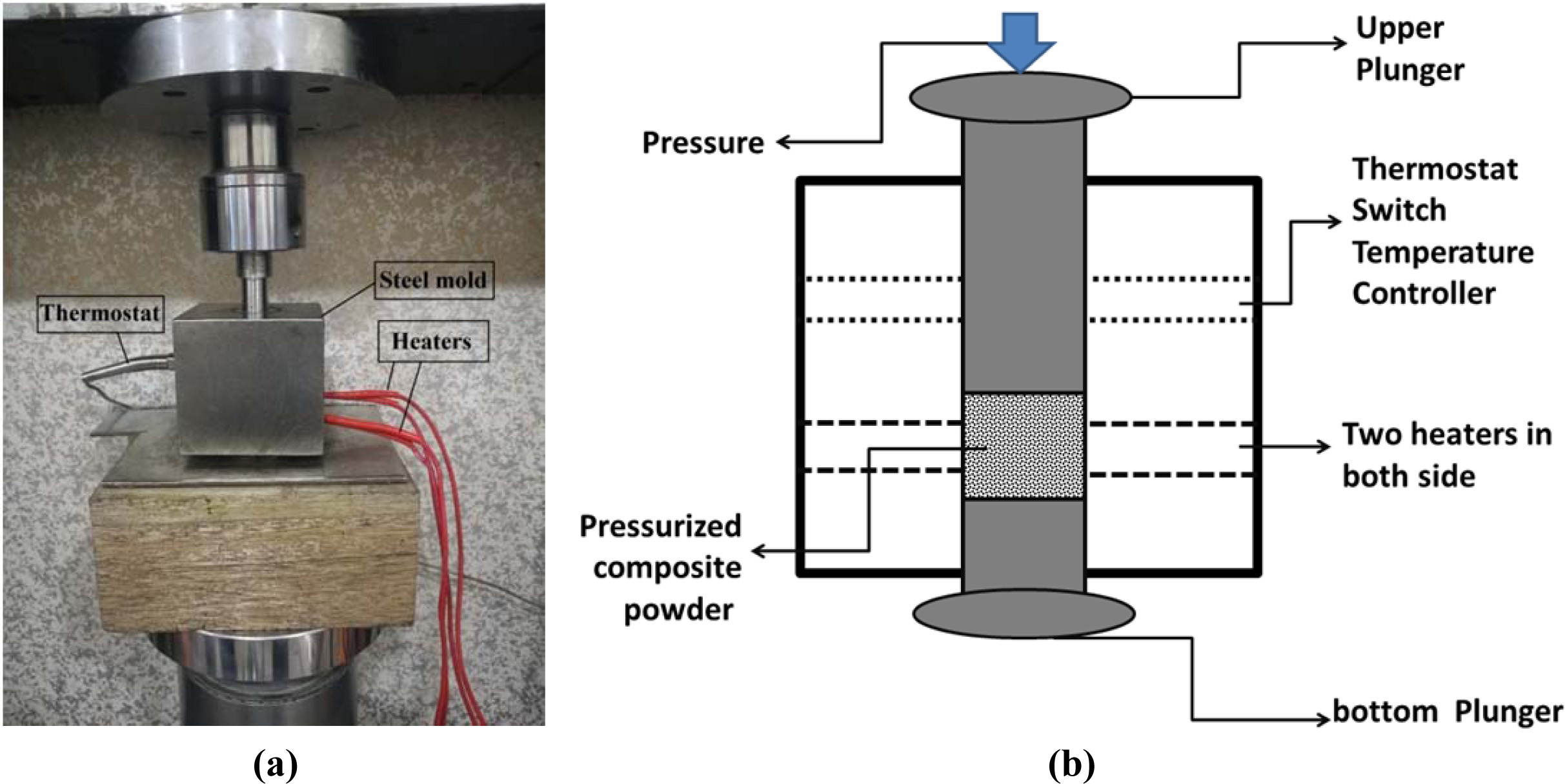
The used HDPE Powder with particle size (5 μm), has been purchased from Right Fortune Industrial Limited (Shanghai, China). The HA nanoparticles were taken from M.K. Nano (Toronto, Canada). With the density of (3.140 gm/cm3), the particle size of 20 nm and the approximately powder purity was 99%. The (MWCNT) with purity 90% were provided from (Cheap Tubes Inc., USA). The hot pressing technique for composite shaping has been employed to fabricate all specimens. The composition of (HA/HDPE) was (40%HA/60%HDPE) chosen with addition (0.6%, 1%, 1.4%, 2%) percentages of MWCNT. Ball milling was used to mixed (HA, HDPE, MWCNT) component with six ceramic balls and (665 rpm) rotational speed during 4 h. The powder prepared in the past steps has been exhibited good homogeneity, as shown in Fig. 1(a). The pressure is applied hydraulically using (Instron 1195), and heating is produced externally using external heaters. The mould was heated to 150 C and held at this temperature for 15 min. The melt pressure value was used 29 MPa for samples moulded. After a (15 min) of applying pressure and heat, the samples were cooled for 2 h until arrive at the room temperature and then the pressure was released. The final form of the samples, pure HA/HDPE and reinforces with various concentrations of MWCNT are displayed in Fig. 1(b). In the hot pressing technique, the temperature and pressure are used in the powder mould, as shown in Fig. 2.
|
Fig. 1 (a) the prepared powder for specimen fabrication powder which contain (40%HA+60%HDPE+1%MWCNT) (b) the form of samples obtained after the hot-pressing technique |
|
Fig. 2 (a) Hot Pressing System (b) schematic diagram (front view) of hot Pressing System. |
The identifying both inorganic and organic crystalline materials of HA/HDPE/MWCNT composites was performed using X-Ray diffraction (XRD) SHIMADZU, Japan XRD 6000 with measuring condition, voltage (40 kV), current (30 mA), drive axis (θ-2θ), scan speed (10.0000 deg/min), sampling pitch (0.2000 deg) and preset time (1.20 sec).
The morphological studies of HA/HDPE/MWCNT nanocomposites samples were examined by Field Emission Scanning Electron Microscopy (FESEM), (FEI Quanta 450, USA) at (1-15 kV). Before the FESEM examination, the nanocomposite samples were coated with a thin film of gold to dissipate the build-up of electrical charges and heat. The atomic force micro- scope (AFM) (Ntegra NT-MDT, Russia) was used to investigate the surface topography (surface roughness and particles size). The examinations were performed in the tapping mode.
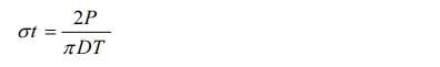
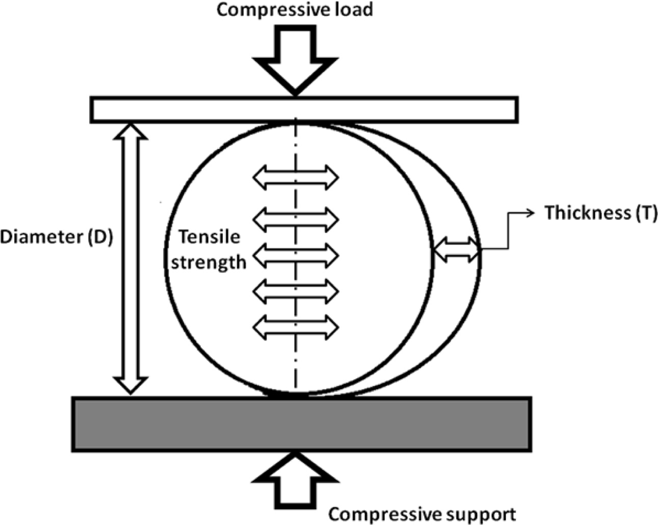
The Brazilian test, indirect tensile test and the diametral compression test are three names for one test procedure that has been used to measure the tensile strength of many types of materials such as ceramics, concrete and polymers [22]. All tests were examined by the (Instron Tinius Olsen H50 KT machine with software QMat 4.53 T series), carried out using scaffolds (Diameters14.75 mm, Width 7 ± 2 mm) with constant velocity rate of 0.5 mm/min. The sample was placed vertically on the testing machine's base and underwent compressive loading until the fracture. The fracture happens along the vertical plane that crosses through the center of the specimen. The tensile stress is directly proportionate to the applied compressive load, shown in Fig. 3. Such diametral tensile strength is determined using the following equation [22]:-
The Vickers microhardness test has been applied to identify hardness values for all samples prepared with varied compression pressures and compositions. Hardness tests are a simple and quick method to identify a material's resistance to deformation. Several different hardness tests applied, which vary in the load applied, the means used to quantify the extent of permanent deformation, and type of indenter applied. Micro-indentation hardness measurement also pointed to as microhardness testing, is usually applied to measure hardness in limited areas, such as surface layers or various microstructural phases. In this research, the Vickers microhardness test has been applied to identify hardness values for all samples prepared with varied compression pressures and compositions. Microhardness tester Digital Micro-Vickers Hardness tester TH714, (Beijing TIME High Technology Ltd., China) was used. For this objective, a load of (25 g) was applied to the sample with a press time of (15 s), show the Fig. 4. Three measurements were recorded at various places on the sample and then taken the average value to the obtained final result.
|
Fig. 3 Schematic diagram of the Brazilian test. |
|
Fig. 4 The notch shape on the sample surface during the microhardness test. |
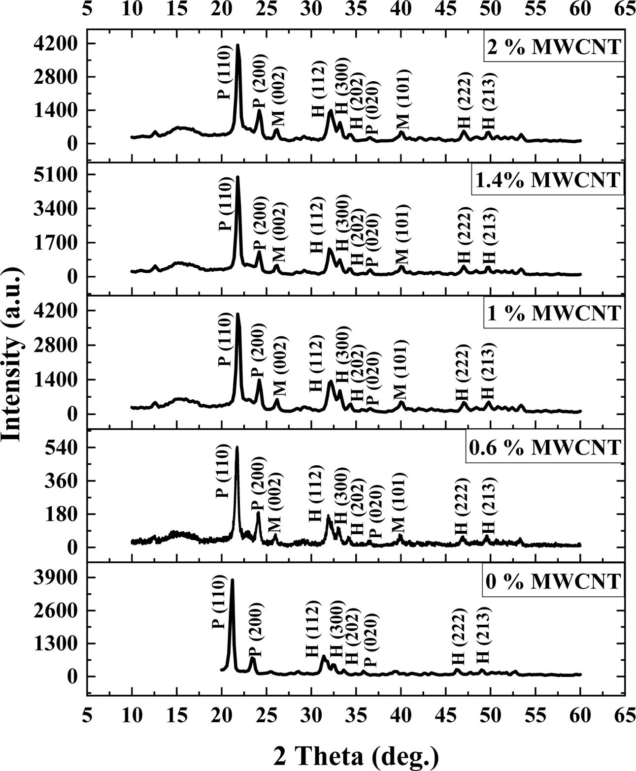
Many important factors influence the presented scaffold properties, such as phase identification of material, surface properties, and mechanical properties, which should be analyzed in the study of tissue engineering. The XRD examination was executed to distinguish various phases existent in the biocomposite (HA/HDPE/MWCNT) specimens, with different MWCNT composition concentrations. XRD characterized the obtained samples to investigate the effect the various percentage of MWCNT on the biocomposite scaffold as shown in Fig. 5. The peaks that appeared in the sample with pressure 29 MPa and 1% MWCNT at 21.8º, 24.2º, 36.6º, are assigned to the HDPE. Also, the peaks at (2θ) position 32.2º, 32.6º, 33.2º, 47º, 49.8º, are associated with the HA. The MWCNT peaks show at 26.2º, 40º. The individual diffraction peaks of HA, HDPE, MWCNT corresponding reflections planes (hkl) of hexagonal graphite JCPDS file number (09-0432), (40-1995) and (41-1487), respectively. The XRD results show strong evidence on the homogeneous mixing of the components reflected on the smooth peaks gained from the test. The XRD diagnosis of the sample surface revealed a homogeneous and good distribution of the components. The ratio of diffraction peak intensity with a percentage (0.6, 1, 1, 4)% of MWCNT, increases incrementally at all material com- ponent of sample composites except in composite that contains 2% MWCNT. The crystallinity of the polymer is directly proportional to the diffraction peak intensity of XRD [23]. So that is indicated the sample of the scaffold with percentage of MWCNT (0.6%), that have a low level of crystallization and the sample of the scaffold with the percentage of MWCNT (1.4%), that have the highest level of crystallization.
The peaks that appeared in the sample with pressure 29 MPa and 1% MWCNT at 21.8º, 24.2º, 36.6º, are assigned to the HDPE. Also, the peaks at (2θ) position 32.2º, 32.6º, 33.2º, 47º, 49.8º, are associated with the HA. The MWCNT peaks show at 26.2º, 40º. The individual diffraction peaks of HA, HDPE, MWCNT corresponding reflections planes (hkl) of hexagonal graphite JCPDS file number (09-0432), (40-1995) and (41-1487), respectively. The XRD results show strong evidence on the homogeneous mixing of the com- ponents reflected on the smooth peaks gained from the test. The XRD diagnosis of the sample surface revealed a homogeneous and good distribution of the com- ponents. The ratio of diffraction peak intensity with a percentage (0.6, 1, 1, 4)% of MWCNT, increases in- crementally at all material component of sample com- posites except in composite that contains 2% MWCNT. The crystallinity of the polymer is directly proportional to the diffraction peak intensity of XRD [23]. So that is indicated the sample of the scaffold with percentage of MWCNT (0.6%), that have a low level of crystallization and the sample of the scaffold with the percentage of MWCNT (1.4%), that have the highest level of crystallization.
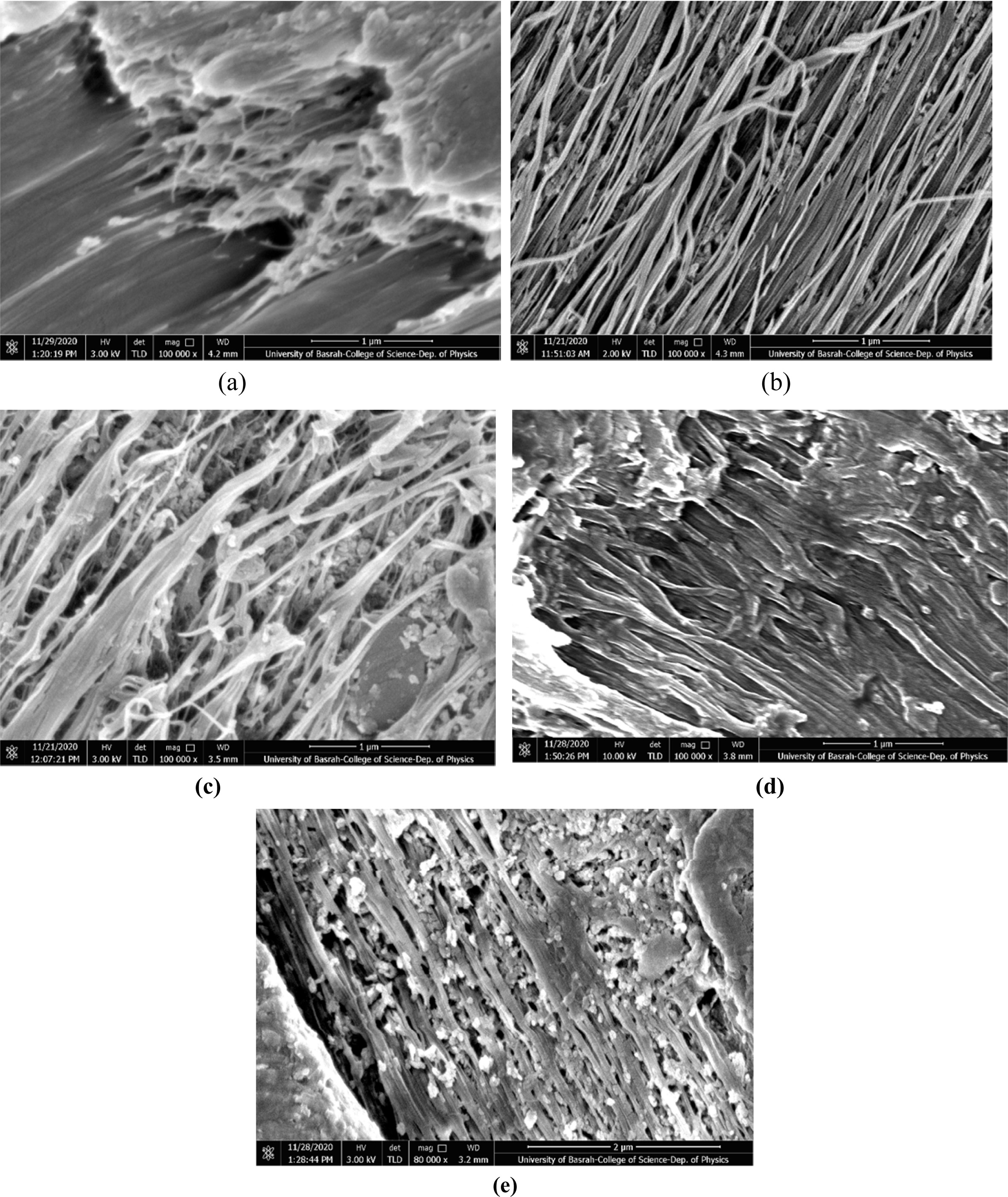
The surface morphologies of HA/HDPE/MWCNT composite specimens were examined using a (FESEM). The investigated specimens ((40%) HA, (60%) HDPE) with various adding % weights of MWCNT, as shown in Fig. 6. The result of the examination specimens with different conditions by FESEM showed not only present better distribution the fibrous network of biomaterial but also scaffold morphology like normal bone. So, the FESEM explained that the construction of HA/HDPE/MWCNT composite was homogeneous, it is seen that the proper for cell growth.
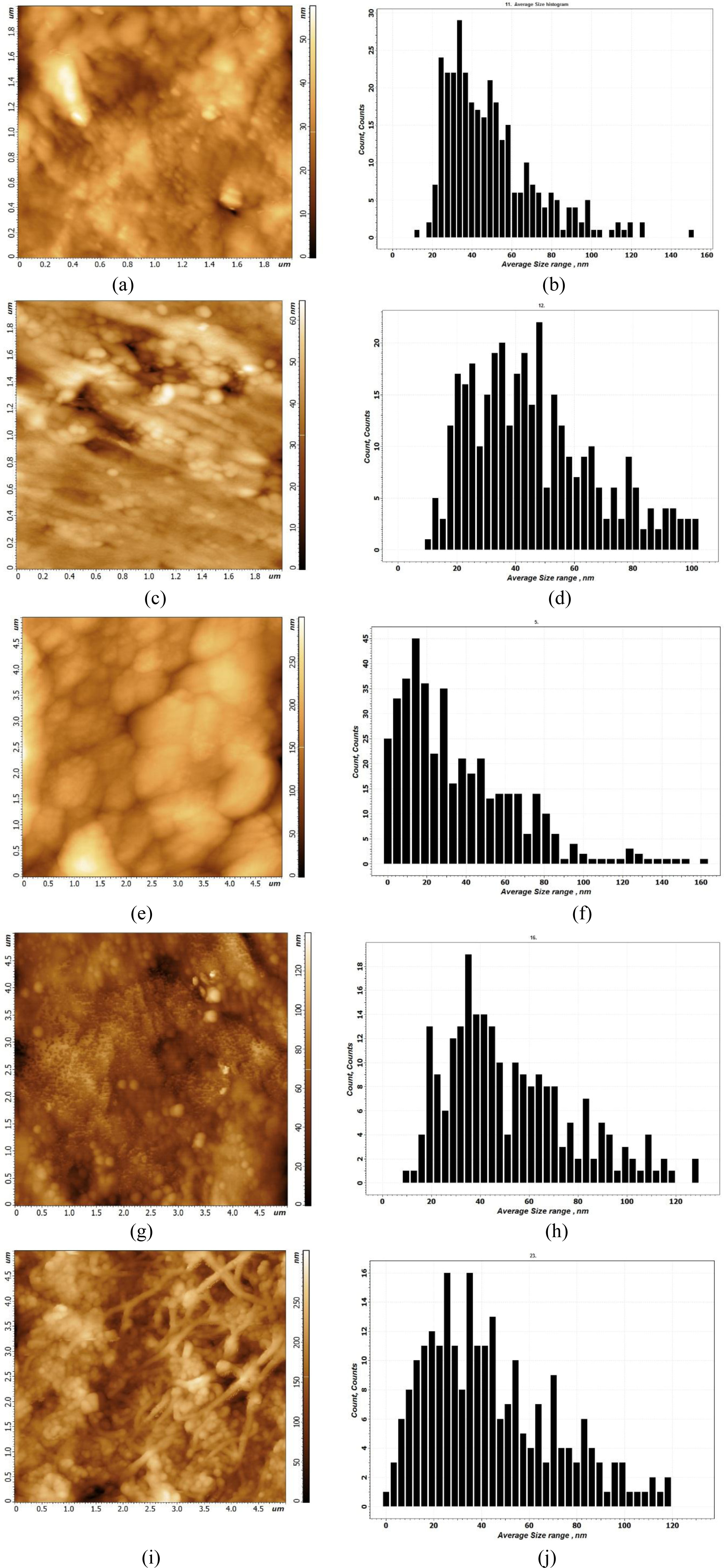
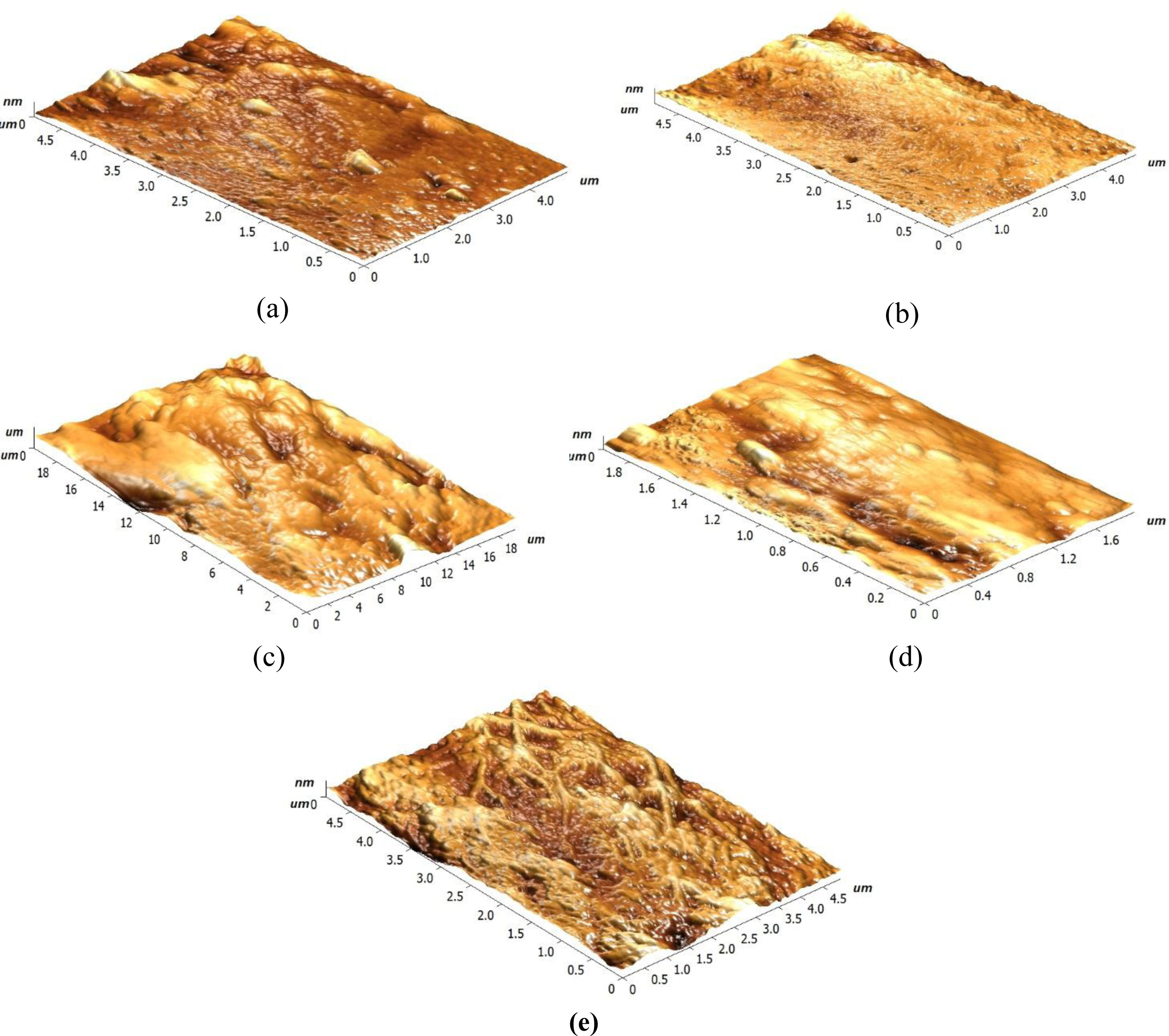
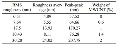
The atomic force microscopy exhibited complex nano-topographies with many submicron-sized and cavities separated uniformly across the samples surfaces. The granularity and microstructure arrangements for the various components of MWCNT in samples (40%HA, 60%HDPE) are shown in Fig. 7. Composite submit a good explanation for the expected mechanical properties. Fig. 8 shows the 3D AFM patterns for the surface roughness tests for the various MWCNT composition specimens. Table 1 listed the differences in the roughness of the sample's surface with various compositions. The Fig. 8 and Table 1 illustrate that the maximum roughness of surface appeared in the sample with composition 40HA/60HDPE/2 MWCNT equal (24.02) nm. The roughness of the sample surface has a significant effect on the increase in differentiation and cell proliferation [24].
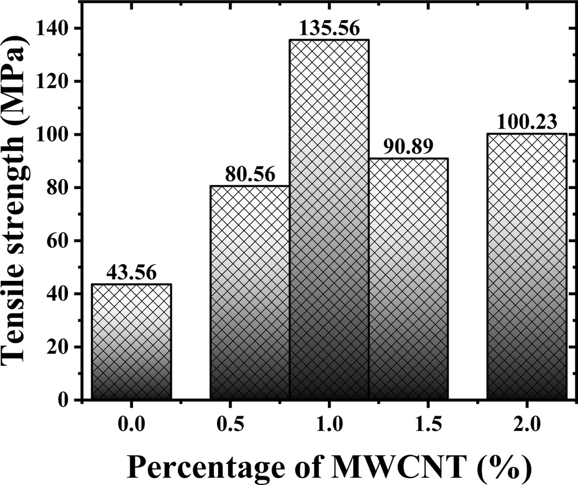
The mechanical strength of the bone scaffold is also an important index that should be taking into account particularly when scaffold with composite material are expected to carry a heavy load. Fig. 9. Shows the relationships between the diametral tensile strength and various percentages of MWCNT compositions. The values of average and SD for tensile strength of samples with (0, 0.6, 1, 1.4, 2) % weights of MWCNT, equal to (90.16 MPa) and (33.26 MPa), respectively. The tensile strength increased along with the increase of additive MWCNT. The highest strength (135.56 MPa) of sample with composite 1% of MWCNT, while the lowest value exhibited in sample with composite 0 % of MWCNT(pure sample HA/HDPE). The tensile strength of the sample with (1%MWCNT) is approxi- mately 3.1 times that tensile strength of pure sample (0% MWCNT). The effects of MWCNT on the composite material are compatible with previous investigations that had confirmed that MWCNT have affirmative effects on the mechanical properties of the scaffold [18, 25]. The improvements achieved and demonstrated by tensile strength examination were moderately close to the characteristics of cortical human bone. As the tensile strength of human bone as mentioned in the [26, 27] is equal to 50-151 MPa.
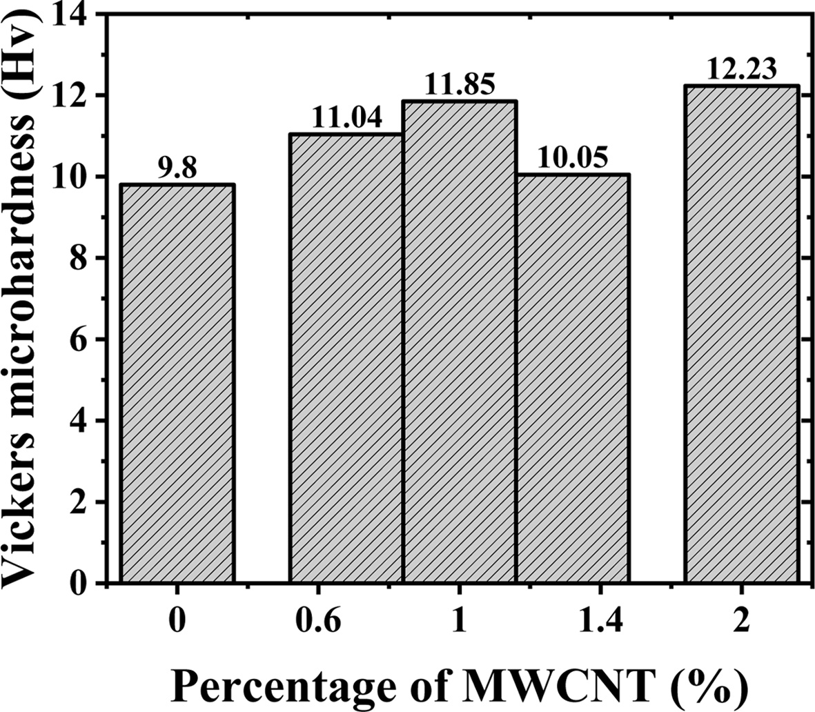
The variety of the Vickers microhardness of the prepared samples is shown in Fig. 10. It can be seen that the Vickers microhardness increased with an increase in MWCNT content, to the maximum value when MWCNT content was up to 2% wt. The values of average and SD for Vickers microhardness of samples with (0, 0.6, 1, 1.4, 2)% weight of MWCNT, equal to (10.994 Hv) and (1.06 Hv), respectively. When adding 2% wt. of MWCNTs affected microhardness by increased up to 24% compared to pure samples HDPE/HA. That it is due to the inhomogeneous distribution of nanotubes in HDPE/HA, with the increase of the MWCNTs concentration, the scatter of data decreases, which shows that with the increase of the amount of MWCNT their distribution in the samples, is further homogeneous. According to Vickers microhardness results, MWCNTs successfully increase the hardness of the composite material HDPE/HA. This relationship between MWCNT and increasing Vickers micro-hardness for HA and HDPE is mentioned in previous research [28, 29].
|
Fig. 5 XRD plots for composite materials samples with different percentage of MWCNT at (40%) of HA and 60% of HDPE under 29 MPa , where (P) , (H),(M) assigned high density polyethylene, hydroxyapatite, MWCNT respectively. |
|
Fig. 6 FESEM image of the composite with 40% HA, 60% HDPE with various percentages of MWCNT (a) 0% MWCNT, (b) 0.6% MWCNT, (c) 1% MWCNT, (d) 1.4% MWCNT, (e) 2% MWCNT. |
|
Fig. 7 The atomic force microscopy (a, c, e, g, i) microstructure representations with (0%, 0.6%, 1%, 1.4%, 2%) of MWCNT respectively and (b, d, f, h, j) granularity distribution with (0%, 0.6%, 1%, 1.4%, 2%) of MWCNT respectivel |
|
Fig. 8 The 3D AFM pictures of surface roughness for different MWCNT compositions: (a) pure sample (0% MWCNT), (b) 0.6% MWCNT, (c) 1% MWCNT, (d) 1.4% MWCNT, (e) 2% MWCNT. |
|
Fig. 9 The tensile strength of samples with variations content of MWCNT. |
|
Fig. 10 The effect of different content of MWCNT on Vickers microhardness. |
|
Table 1 AFM parameters (Peak-peak distance, roughness average, and Root mean square (RMS) roughness) for samples with different compositions, at 29 hot-press pressure |
The HA/HDPE with various amounts of MWCNT was fabricated using the hot-pressing technique in the present investigation. The biocompatibility is considered in the selection of the scaffold components. The XRD and AFM diagnosis of the sample surface revealed a homogeneous, good distribution of the components' microstructure arrangements. This indicates the best achievement of the sample preparation and fabrication method. The typical fibres shape, similar to the structure of bone tissue, was exhibited in FESEM examination. Describe the present samples' mechanical characteristics by performing the indirect tensile strength (Brazilian test) for tensile strength and microhardness test magnitude. The results confirmed that the addition of the MWCNT had improved the composites. The individual features of the presented samples in this investigation with homogeneous fibrous shape and high mechanical properties could be applied in bone tissue repair in many cases of bone diseases.
The authors gratefully acknowledge to the Dr Mazin Auny Mahdi /college of science/ University of Basra/Iraq, for assist to complete FESEM examination.
- 1. G. Battafarano, M. Rossi, V. De Martino, F. Marampon, L. Borro, A. Secinaro, and A. Del Fattore, Int. J. Mol. Sci. 22[3] (2021) 1128.
-

- 2. B.M. Manzini , L.M.R. Machado, P.Y. Noritomi, and J.V.L. da Silva, J. Biosci. 46[1] (2021) 1-18.
-
- 3. S. Standring, in “Gray’s anatomy e-book: the anatomical basis of clinical practice” (Elsevier Health Sciences, 2015) p.83.
- 4. N.N. Hung, in “Basic knowledge of bone grafting” (InTech, 2012) p.11-38.
- 5. S. Deb, in “Orthopedic bone cement” (Wiley Encycl. Biomed. Eng., 2006) p.1-34.
-
- 6. B.D. Ratner, A.S. Hoffman, F.J. Schoen, and J.E. Lemons, MRS Bull 31[1] (2006) 58-60.
-
- 7. C. Gao, S. Peng, P. Feng, and C. Shuai, Bone Res. 5[1] (2017) 1-33.
-
- 8. M. Ahmad, M.U. Wahit, M.R. Abdul Kadir, and K.Z. Mohd Dahlan, The Scientific World Journal 2012 (2012) 1-13.
-
- 9. R.Z. LeGeros, Chem. Rev. 108[11] (2008) 4742-4753.
-
- 10. W. Bonfield, M.D. Grynpas, A.E. Tully, J. Bowman, and J. Abram, Biomaterials 2[3] (1981) 185-186.
-
- 11. D.S. Seo, K.H. Hwang, S.Y. Yoon, and J.K. Lee, J. Ceram. Proc. Res. 13[5] (2012) 586-589.
- 12. N.A.M. Radzuan, A.B. Sulong, F.M. Foudzi, M.Y. Zakaria, and M.I. Ramli, J. Ceram. Proc. Res. 21[6] (2020) 662-666.
-
- 13. H. Fouad, R. AlFotawi, O.Y. Alothman, B.A. Alshammari, M. Alfayez, M. Hashem, and A. Mahmood, Materials (Basel) 11[4] (2018) 521.
-
- 14. J.S. Kashan, A. Jha, A.D. Thamir, and J.T. Al-Haidary, J. King Saud Univ. Sci. 30[4] (2018) 286-295.
-
- 15. B. Majkowska-Marzec, D. Rogala-Wielgus, M. Bartmański, B. Bartosewicz, and A. Zieliński, Coatings 9[10] (2019) 643.
-
- 16. Y. Akgul, H. Ahlatci, M.E. Turan, H. Simsir, M.A. Erden, Y. Sun, and A. Kilic, Polym. Compos 41[6] (2020) 2426-2432.
-
- 17. J. Xu, X. Hu, S. Jiang, Y. Wang, R. Parungao, S. Zheng, Y. Nie, T. Liu, and K. Song, Polymers (Basel). 11[2] (2019) 230.
-
- 18. K. Lawton, H. Le, C. Tredwin, and R.D. Handy, Int. J. Nanomedicine 14 (2019) 7947-7962.
-
- 19. M. Wang, R. Joseph, and W. Bonfield, Biomaterials 19[24] (1998) 2357-2366.
-
- 20. M. Wang, Biomaterials 24[13] (2003) 2133-2151.
-
- 21. D. Lahiri, S. Ghosh and A. Agarwal, Mater. Sci. Eng. C 32[7] (2012) 1727-1758.
-
- 22. M.K. Fahad, J. Mater. Sci. 31[14] (1996) 3723-3729.
-
- 23. D. Li, L. Zhou, X. Wang, L. He, and X. Yang, Materials (Basel). 12[11] (2019) 1746.
-
- 24. C. Liang, Y. Luo, G.Yang, D. Xia, L. Liu, X. Zhang, and H. Wang, Nanoscale Res. Lett. 13[1] (2018) 1-10.
-
- 25. C.Z. Liao, K. Li, H.M. Wong, W.Y. Tong, K.W.K. Yeung, and S.C. Tjong, Mater. Sci. Eng. C 33[3] (2013) 1380-1388.
-
- 26. L.C. Gerhardt and A.R. Boccaccini, Materials (Basel). 3[7] (2010) 3867–3910.
-
- 27. K. Rezwan, Q.Z. Chen, J.J. Blaker, and A.R. Boccaccini, Biomaterials 27[18] (2006) 3413-3431.
-
- 28. M.S. Barabashko, M.V. Tkachenko, A.A. Neiman, A.N. Ponomarev, and A.E. Rezvanova, Appl. Nanosci. 10 (2020) 2601-2608.
- 29. S. Dabees, B. M. Kamel, V. Tirth, and A. B. Elshalakny, Bioengineered 11[1] (2020) 679-692.
-
 This Article
-
2021; 22(4): 446-454
Published on Aug 31, 2021
- 10.36410/jcpr.2021.22.4.446
- Received on Jan 16, 2021
- Revised on May 4, 2021
- Accepted on May 14, 2021
Services
- Abstract
introduction
materials and methods
materials characterization techniques
results and discussion
conclusions
- Acknowledgements
- References
- Full Text PDF
Shared
Correspondence to
- Ali A. Al-allaq
-
aMinistry of Higher Education and Scientific Research, Office Reconstruction and Projects ,Baghdad, Iraq
bBiomedical Engineering Department ,Faculty of Engineering, Helwan University Cairo, Egypt
Tel : +964 7721082705 - E-mail: ali.martial85@gmail.com, ali.martial85@h-eng.helwa
Clean-Energy Research Institute(CRI), Hanyang University, 222, Wangsimni-ro, Seongdong-gu, Seoul, 04763, Korea
E-mail: jcpr@hanyang.ac.kr