


- Hetero-shaped mesoporous structure of carbon nanofibers for high-performance electrical double layer capacitors
Kue-Ho Kim, Ju-Young Kim and Hyo-Jin Ahn*
Department of Materials Science and Engineering, Seoul National University of Science and Technology, Seoul 01811, Korea
This article is an open access article distributed under the terms of the Creative Commons Attribution Non-Commercial License (http://creativecommons.org/licenses/by-nc/4.0) which permits unrestricted non-commercial use, distribution, and reproduction in any medium, provided the original work is properly cited.
Boosting the performance of electrical double layer capacitors (EDLCs) without degradation of power density or lifespan demands innovative modification of electrode materials in order to have both sufficient surface area and fast ion diffusion kinetics. Herein, carbon nanofibers (CNFs) with a unique hetero-shaped mesoporous structure were reported via decomposition of poly (methyl methacrylate) (PMMA) and dissolution of ZnO nanoparticles during the carbonization process. To optimize electrochemical performance, the amount of ZnO nanoparticles was varied from 0 to 0.5, 1.5, or 2.5 wt%. As a result, hetero-shaped mesoporous CNFs with 1.5 wt% ZnO nanoparticles (1.5ZnO-PCNF) exhibited the largest surface area of 691.6 m2 g-1, providing sufficient electrochemical active sites. Moreover, 1.5ZnO-PCNF showed the highest mesopore volume fraction of 92.5%, leading to fast ion diffusion kinetics. The optimized 1.5ZnO-PCNF electrode showed a specific capacitance of 120 F g-1 at a current density of 0.2 A g-1, 91.6% capacitance retention at a current density of 2 A g-1, and excellent cycling stability up to 3,000 cycles (maintaining 75.8% of capacitance after 3,000 cycles). These improvements in performance were mainly attributed to a well-generated hetero-shaped mesoporous structure with a large specific surface area
Keywords: Electrical double layer capacitors, Carbon nanofibers, hetero-shaped mesopore, cycling stability, rate performance
As the requirement for renewable energy sources has continuously increased because of depletion of global fossil energy resources, electrochemical energy storage devices have attracted considerable attention around the globe. Electrochemical energy storage devices, such as supercapacitors (SCs) and Li-ion batteries (LIBs), use electrochemical reactions during the charge/discharge process, and possess the advantages of eco-friendliness, sustainable usage, and high energy efficiency [1-3]. In particular, SCs offer promising energy storage performance, which allows high power density, long lifespan, and high charging/discharging rate [4-7]. Conventional SCs consist of an electrode (including an active material and a current collector) and an electrolyte. Among various types of SCs, electrical double-layer capacitors (EDLCs) utilize physical adsorption and desorption of charge carriers at the interface of the electrode and electrolyte by electrostatic force. Therefore, the surface morphology of active materials is one of the main factors that can modify the interfacial characteristics of the electrode and electrolyte, determining the energy storage performance of EDLCs [8-10].
Currently, carbon materials offer various advantages such as high electrical conductivity, excellent electro- chemical stability, and low cost. However, carbon-based electrodes have inherent performance limitations owing to their low specific surface area and low mesopore volume fraction. In this regard, several strategies to overcome these challenges have been reported, such as pore generation and the development of composite structures with activated materials on a carbon matrix [11-16]. However, these strategies have concentrated on enhancing specific capacitance and energy density, rather than rate capability and cycling stability. Therefore, a novel approach to achieve high specific capacitance and energy density, as well as high rate performance and cycling stability is required. For example, Lu et al. reported porous carbon nanofibers (CNFs) using centrifugal spinning method, exhibiting 96 F g-1 at a current density of 2 A g-1. Their porous CNFs showed superior cycling stability of 90% after 1,000 cycles with high specific surface area of 450 m2 g-1 [17]. Nevertheless, the introduction of hetero-shaped mesoporous structures in CNFs remains a critical challenge for high-performance EDLCs applications.
Here, we propose a hetero-shaped (linear and spherical) mesoporous structure of CNFs as an active material for the electrode of EDLCs. To develop a hetero-shaped mesoporous morphology, decomposition of PMMA and dissolution of ZnO nanoparticles within CNFs were induced during the carbonization process. Especially, Pore generation method using ZnO nanoparticles has distinctive advantage of pore size controllability through adjusting the particle size of ZnO. This unique structure with a high mesopore volume fraction enables optimized specific capacitance, rate performance, and cycling stability in EDLCs. To demonstrate their performance enhancement, we conducted morphological, structural, and chemical analyses and identified correlations with electrochemical characteristics.
CNFs with hetero-shaped mesoporous structures were successfully fabricated using electrospinning and carbonization methods. To prepare a solution for electrospinning, 10 wt% polyacrylonitrile (PAN, Mw = 150,000 g/mol, Aldrich) and 10 wt% poly (methyl methacrylate) (PMMA, Mw = 120,000 g/mol, Aldrich) were dissolved in N,N-dimethylformamide (DMF, 99.8%, Aldrich). In order to optimize the hetero-shaped mesoporous structure, which leads to the desired electrochemical performance, different amounts of zinc xide (ZnO, nanopowder, 97%, < 50 nm, Aldrich) were added to the solution (0, 5, 15, and 25 wt% of the solvent) (thereafter identified as PCNF, 0.5ZnO-PCNF, 1.5ZnO-PCNF, and 2.5ZnO-PCNF). The feeding rate, voltage, and needle distance were maintained at 0.05 mL h-1 , 16 kV, and 15 cm, respectively. Then, the as-spun samples were carbonized at 800 oC for 2 h in nitrogen after stabilization at 280 oC for 2h in air. After carbonization, all the samples were washed with hydrochloric acid (HCl, 37%, Samchun) to remove the embedded ZnO nanoparticles within the CNFs, which led to the mesoporous structure. The resultant samples were washed with deionized water and, completely dried in an 80 oC oven for 12 h.
To characterize the surface morphology of all the samples, field-emission scanning electron microscopy (FESEM, Hitachi S-4800) measurement was carried out. The crystal structure and chemical bonding state were evaluated using X-ray diffractometry (XRD, Rigaku D/MAX-2500) and X-ray photoelectron spectroscopy (XPS, ESCALAB 250), respectively. The pore structures of the samples were examined using Brunauer-Emmett-Teller (BET) and Barrett-Joyner-Halenda (BJH) methods with N2 adsorption. Electrochemical measurements were conducted using a two-electrode system with Ni foam (MTI Korea) current collectors and 6 M KOH electrolyte. The electrode paste mixture was prepared with the 0.1 g of active materials (70 wt%), Ketjan black (Mitsubishi Chemical, ECP-600JD) (10%), and polyvinylidene difluoride (PVDF, Alfa Aesar) (20%) in N-methyl-2-pyrrolidone (NMP, 99.5%, Aldrich) solvent and dried in an oven at 100 oC after being coated on Ni foam (all resultant electrodes possess ~ 0.002 g of the respective active materials). Electrochemical measure- ments were conducted using a potentiostat/galvanostat (Ecochemie Autolab, PGST302N). Cyclic voltammetry (CV) was performed in the potential range 0-1 V, and a charge/discharge test for calculating the specific capacitance was performed in the current density range 0-2 A g-1. To evaluate the cycling stability, the specific capacitance of all the electrodes was measured up to 3,000 cycles at a current density of 1 A g-1.
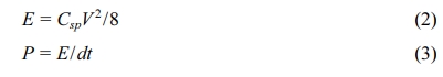
We successfully developed hetero-shaped mesoporous structures of CNFs, and Fig. 1 presents a schematic illustration of the synthetic procedure using electrospinning and carbonization. Fig. 1(a) shows an as-spun CNF comprised of a PAN matrix, ZnO nanoparticles, and agglomerated PMMA. This PMMA agglomeration is attributed to a phase separation between PAN and PMMA due to their different surface tensions and molecular weights [18]. So, the PAN formed the matrix and PMMA formed the agglomerated linear morphology within the matrix, maintaining their individual state. When the temperature reached 300 oC, the PMMA started to decompose and generated linear mesopores in the nanofibers (Fig. 1b). In addition, ZnO nanoparticles were reduced in the N2 atmosphere and transformed to a metallic zinc (melted above 419.5 oC), which generated spherical mesopores [19]. Finally, Fig. 1(c) shows the successfully developed hetero-shaped (linear and spherical) mesoporous structure of the CNF, which can provide additional active sites and favorable ion diffusion pathways during an electrochemical reaction [20, 21].
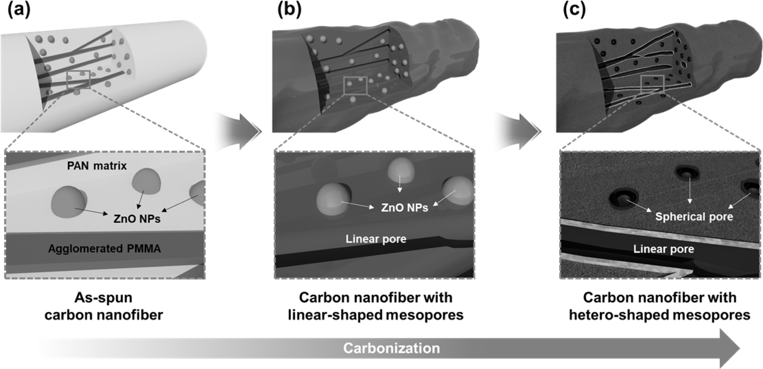
Fig. 2 displays low and high-resolution FESEM images of PCNF, 0.5ZnO-PCNF, 1.5ZnO-PCNF, and 2.5ZnO-PCNF, respectively. In the case of PCNF (Fig. 2a and 2e), one-dimensional nanofibers with a linear mesoporous structure is observed. This implies that the PMMA decomposition during carbonization process can develop uniform linear-shaped mesopores within the CNFs. Distinctively, the 0.5ZnO-PCNF (Fig. 2b and 2f) show a hetero-shaped mesoporous structure with linear and spherical pores. This unique morphology is caused by the synergistic effect of PMMA decom- position and ZnO dissolution during the carbonization process. In the 1.5ZnO-PCNF (Fig. 2c and 2g), the distribution of spherical type pores is enhanced with an increase in the amount of ZnO nanoparticles from 0.5 wt% to 1.5 wt%. The optimized hetero-shaped mesoporous structure of CNF can contribute to the improvement of the electrochemical performance by supplying additional active sites and shorter ion diffusion path. However, in the 2.5ZnO-PCNF (Fig. 2d and 2h), a destroyed CNF structure with nonuniform pore distribution is observed due to the excessive amount of ZnO nanoparticles (2.5 wt%). The discontinuous morphology of the CNF structure might induce a significant decline in electrical conductivity and an increase in electrochemical resistance, which would degrade the electrochemical activity [22]. Thus, the 1.5ZnO-PCNF shows the optimized CNF morphology of hetero-shaped mesoporous structure with enlarged active sites.
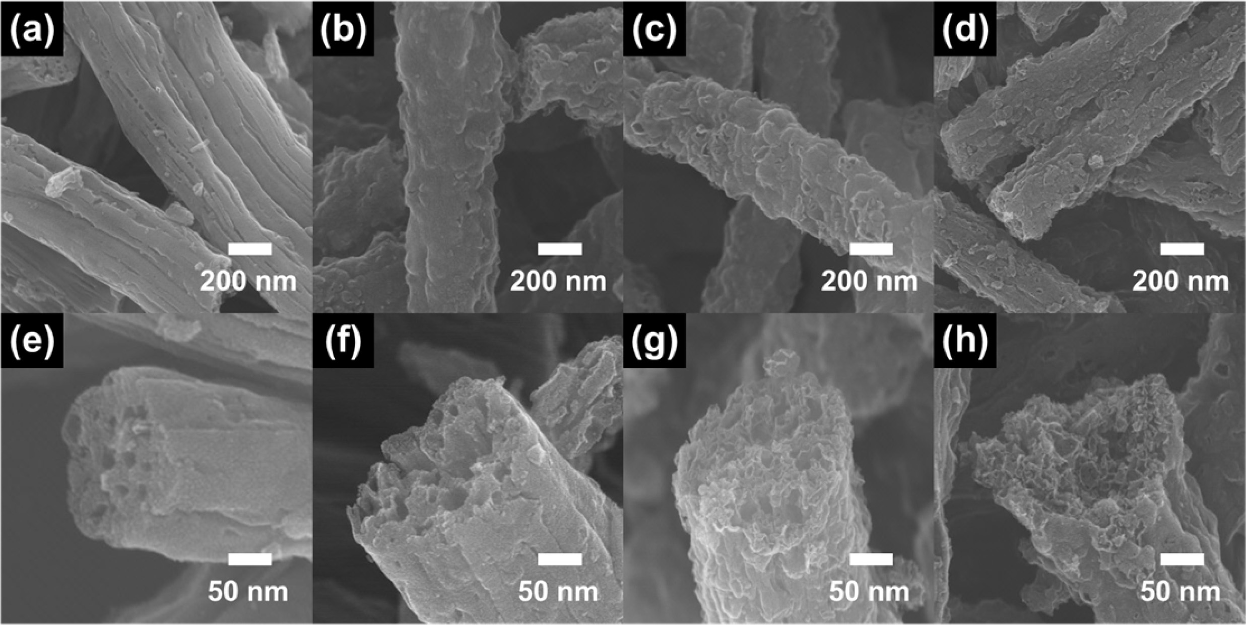
Fig. 3(a) presents the XRD patterns of PCNF, 0.5ZnO-PCNF, 1.5ZnO-PCNF, and 2.5ZnO-PCNF, which were analyzed to investigate their crystal structure. All the samples exhibit a broad diffraction peak at ~ 25.0o, which corresponds to the (002) plane of graphite. The broadness of the diffraction peak implies the formation of amorphous CNFs due to the low carbonization temperature of 800 oC. In the XRD patterns of PCNF, 0.5ZnO-PCNF, and 1.5ZnO-PCNF, no other discernible peaks are observed besides, the broad graphitic peak. On the other hand, 2.5ZnO-PCNF shows peaks at ~31.8o, ~ 36.3o, ~ 56.6o, and ~ 66.4o, corresponding to the (100), (101), (110), and (200) planes, respectively, of ZnO (JCPDS card No. #79-2205) [23]. These peaks are due to residual ZnO nanoparticles within the CNFs after the carbonization process due to an excess amount of ZnO nanoparticles. Moreover, we performed XPS measurements of 0.5ZnO-PCNF, 1.5ZnO-PCNF, and 2.5ZnO-PCNF to confirm their chemical bonding state. The binding energy levels were standardized by the C 1s line at 284.5 eV as a reference. For the Zn 2p XPS core-level spectra (Fig. 3b), only 2.5ZnO-PCNF shows a pair of doublets at ~1,045.4 eV for Zn 2p1/2 and ~1,022.6 eV for Zn 2p3/2 [24]. This result also supports the existence of ZnO nanoparticles within the CNFs after the carbonization process. The residual ZnO nano- particles likely occupy pore sites and increase the electrode weight, which would lead to severe degradation of the specific capacitance. Therefore, the 1.5ZnO-PCNF electrode is expected to demonstrate the best electrochemical performance without any residual ZnO nanoparticles in the CNF.
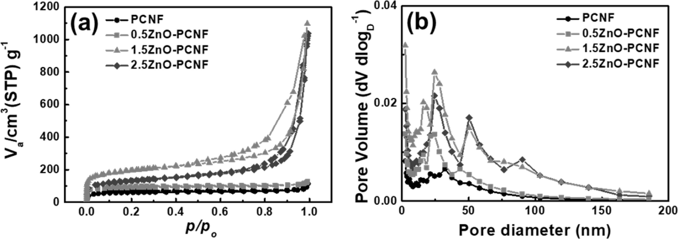
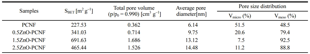
Fig. 4 shows the result of BET and BJH analysis for PCNF, 0.5ZnO-PCNF, 1.5ZnO-PCNF, and 2.5ZnO-PCNF to determine their pore structure by N2 adsorption/desorption. In accordance with the IUPAC (International Union of Pure and Applied Chemistry) classification, the pores can be categorized into three types based on their pore diameter: micropores (under 2 nm), mesopores (from 2 nm to 50 nm), and macropores (over 50 nm) [25, 26]. In Fig. 4(a), the isotherms of PCNF and 0.5ZnO-PCNF showed no discernible behavior due to their very low specific surface area. In contrast, isotherms of 1.5ZnO-PCNF and 2.5ZnO-PCNF show type IV behavior at high N2 pressure, which indicates the successful development of mesopores. In particular, 1.5ZnO-PCNF shows the largest curve area with optimized hetero-shaped mesoporous CNF morphology. As shown in the BJH result for all samples (Fig. 4b), the mesopore volume (pore diameter range of 2-50 nm) gradually increases from PCNF to 0.5ZnO-PCNF and 1.5ZnO-PCNF, supporting the generation of spherical mesopores due to the added ZnO nanoparticles. However, the mesopore volume of 2.5ZnO-PCNF decreas despite the highest amount of ZnO nanoparticles. This result demonstrates that an excessive amount of ZnO nanoparticles can destroy the CNF structure and form discontinuous morphology, which is confirmed by the FESEM images (Fig. 2d and 2h). Table 1 summarizes the results of pore structure evaluation for all the samples. The specific surface area (SBET) gradually increases from 227.53 m2 g-1 for PCNF to 341.03 m2 g-1 for 0.5ZnO-PCNF and 691.63 m2 g-1 for 1.5ZnO-PCNF, which is higher than that of 2.5ZnO-PCNF (465.44 m2 g-1). Moreover, 1.5ZnO-PCNF presents the largest mesopore volume fraction of 92.5%, compared with 0.5ZnO-PCNF (79.4%) and 2.5ZnO-PCNF (88.8%), which affects the electrochemical performance enhancement at a high current density with a favorable ion diffusion pathway [27, 28].
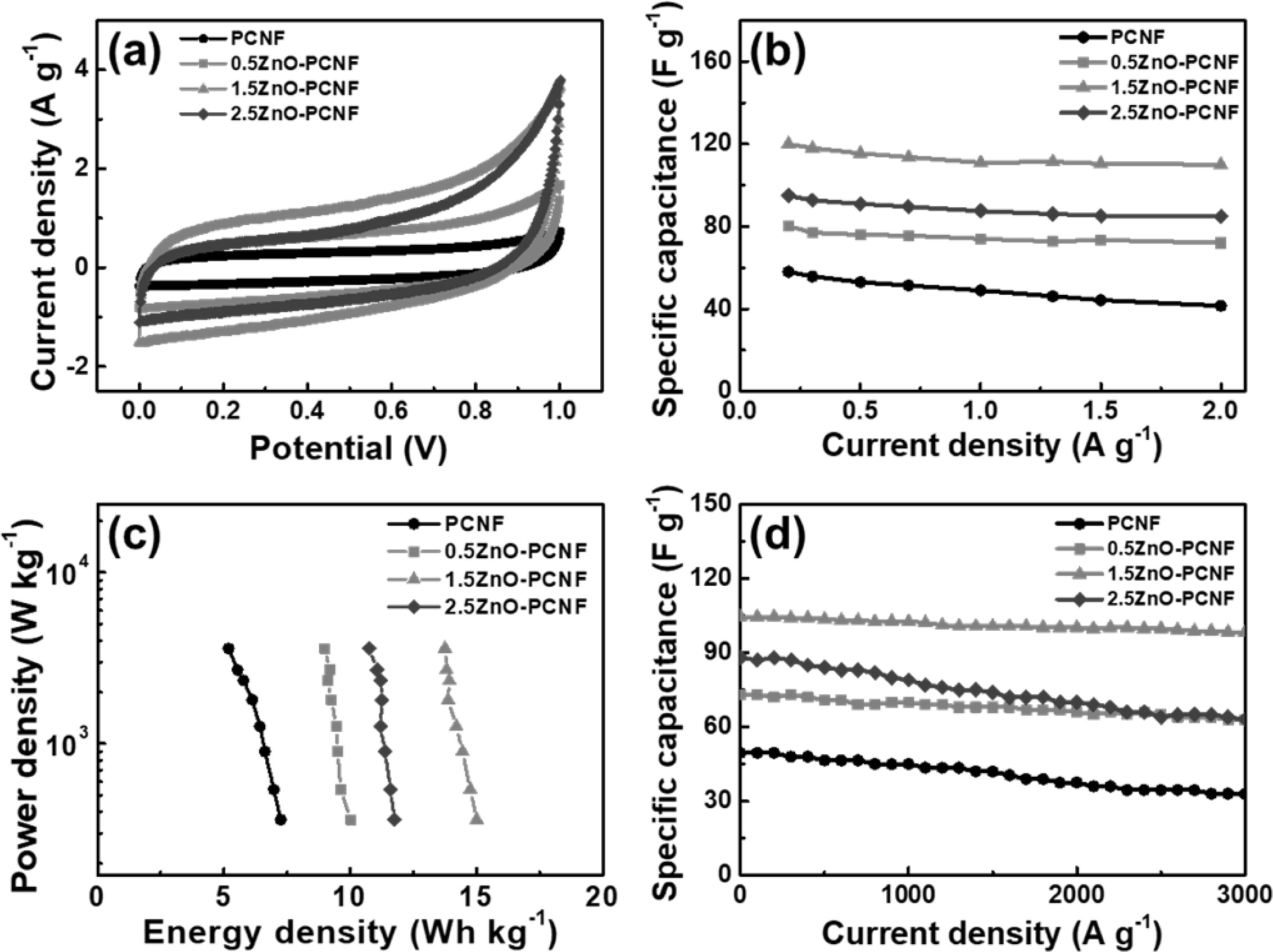
To investigate the electrochemical performance of all the samples, CV measurements were performed in the potential range 0-1 V and a scan rate of 10 mV/s using a conventional two-electrode system. All electrodes show rectangular CV curves (Fig. 5a) due to the typical electrical double-layer region at the interface of the electrode and electrolyte. The 1.5ZnO-PCNF exhibits the largest area under the CV curve among all the electrodes, corresponding to high electrochemical activity from a large specific surface area. Fig. 5(b) shows the specific capacitance (Csp) data in the current density range from 0.2 to 2 A g-1 for all electrodes, which were deduced from the charge/discharge test. For the calculation, the following equation was applied for all electrodes (Eq. 1) [29, 30]:

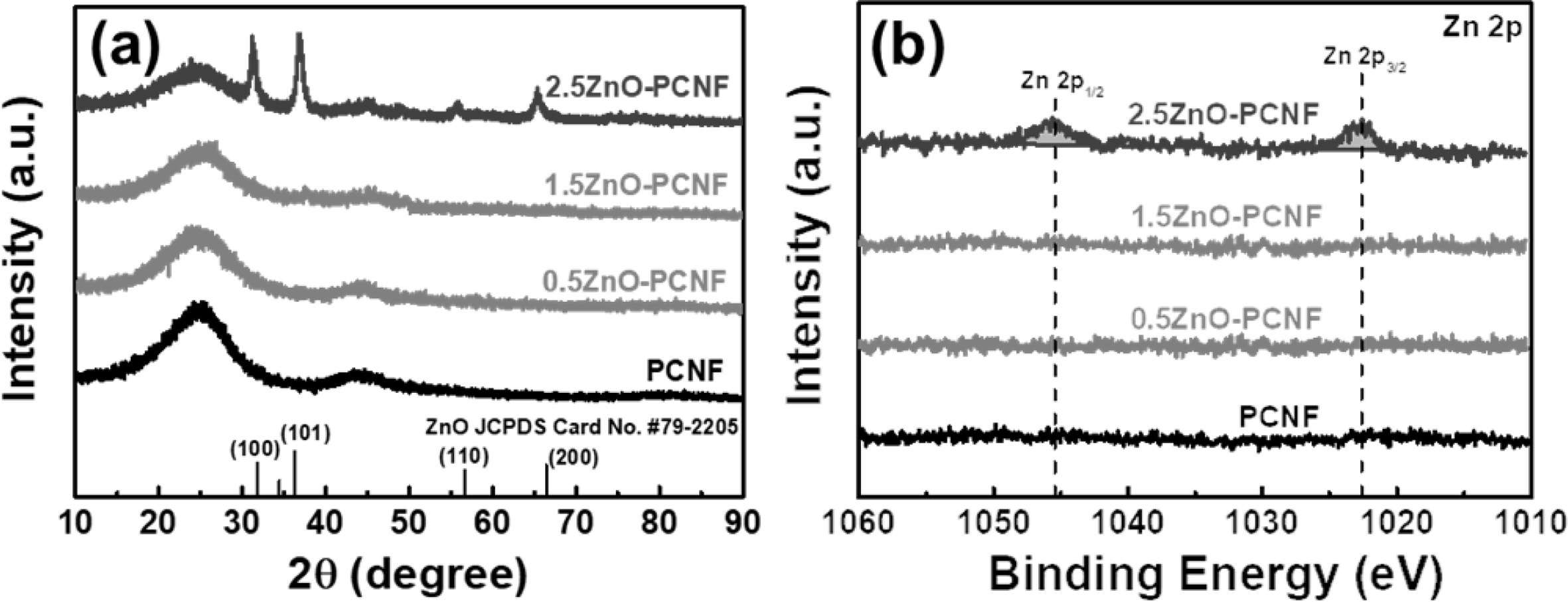
In the equation, I (A), m (g), dV, and dt represent the applied current, active material mass, discharging voltage window, and discharging time, respectively. The specific capacitances of the PCNF, 0.5ZnO-PCNF, 1.5ZnO-PCNF, and 2.5ZnO-PCNF electrodes at a low current density of 0.2 A g-1 were 58, 80, 120, and 94 F g-1, respectively. The excellent specific capacitance of the 1.5ZnO-PCNF electrode is caused by its high specific surface area compared with that of the other electrodes. The 1.5ZnO-PCNF electrode showed a superior capacitance retention rate of 91.6% (110 F g-1 at a current density of 2 A g-1) with a high mesopore volume fraction (92.5%). In contrast, the PCNF electrode showed an inferior capacitance retention rate of 71.5% (41.5 F g-1 at a current density of 2 A g-1) with a low mesopore volume fraction (48.5%). These results confirm that the hetero-shaped mesoporous structure of 1.5ZnO-PCNF is the optimum structure within the range tested and demonstrate the correlation between high-rate performance and mesopore volume fraction. Fig. 5(c) shows the Ragone plot, showing energy density (E, W h/kg) and power density (P, W/kg) calculated from specific capacitance values by Equations 2 and 3 [31, 32]:
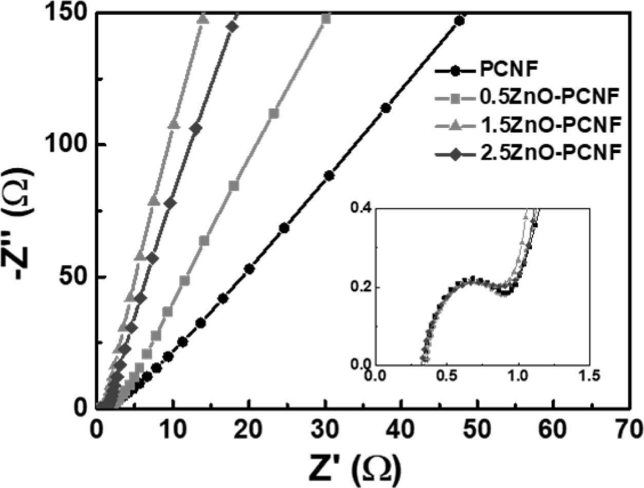
In the above equations, Csp, V, and dt signify the specific capacitance, discharging voltage, and discharging time, respectively. The energy density values of all electrodes decrease with an increase in power density because of capacity degradation at a high current density. The 1.5ZnO-PCNF electrode, possessing a high mesopore volume fraction, exhibits a high energy density of 15.0-13.8 W h/kg at a power density of 360-3,600 W/kg. Meanwhile, the PCNF electrode, with a low mesopore volume fraction, shows an energy density of 7.3-5.2 W h/kg at the same power density. To investigate the cycling stability, repeated charge/discharge cycling tests were performed for 3,000 cycles at a current density of 1 A g-1 (Fig. 5d). Among the electrodes, 1.5ZnO-PCNF presented excellent cycling stability, maintaining 79.3 F g-1 after 3,000 cycles (75.8% capacitance retention), while PCNF presented poor cycling stability, maintaining 33.0 F g-1 after 3,000 cycles (66.7% capacitance retention). The difference in cycling stability is also attributed to the mesopore volume fraction, which can affect the ion transfer efficiency and determine stability during the charge/discharge test. Fig. 6 shows the Nyquist plots for all electrodes at the open-circuit potential. Interestingly, the 1.5ZnO-PCNF electrode exhibits the steepest straight line at the low-frequency region, which implies ionic diffusion ability regarding the Warburg impedance [33, 31]. This result indicates that the large mesopore volume fraction of 1.5ZnO-PCNF provides a short ion diffusion pathway, improving ionic diffusion ability during the electrochemical reaction.
Therefore, the optimum electrochemical performance was that of the hetero-shaped mesoporous 1.5ZnO-PCNF electrode. This novel structure was achieved by linear and spherical mesopores generated by the decomposition of PMMA and dissolution of ZnO nanoparticles within the CNFs during the carbonization process. The first contributing factor for performance enhancement was the enlarged specific surface area, providing a high specific capacitance at a low current density. A second important factor was the optimized mesopore volume fraction, leading to an excellent rate performance at a high current density and good cycling stability by generating a favorable ion diffusion pathway. Thus, CNFs with hetero-shaped mesopores could be a promising medium as the active material of EDLCs.
|
Fig. 1 Schematic illustration of hetero-shaped mesoporous structure of carbon nanofiber. (a) as-spun carbon nanofiber, (b) carbon nanofiber with liner-shaped mesopores, and (c) carbon nanofiber with hetero-shaped mesopores. |
|
Fig. 2 Low-resolution (a-d) and high resolution (e-h) FESEM images of PCNF (a,e), 0.5ZnO-PCNF (b,f), 1.5ZnO-PCNF (c,g), and 2.5ZnO-PCNF (d,h). |
|
Fig. 3 (a) XRD curves and (b) XPS core-level spectra of Zn 2p for PCNF, 0.5ZnO-PCNF, 1.5ZnO-PCNF, and 2.5ZnO-PCNF. |
|
Fig. 4 (a) BET result using N2 adsorption/desorption and (b) BJH pore size distribution of PCNF, 0.5ZnO-PCNF, 1.5ZnO-PCNF, and 2.5ZnO-PCNF. |
|
Fig. 5 (a) CV curves of PCNF, 0.5ZnO-PCNF, 1.5ZnO-PCNF, and 2.5ZnO-PCNF electrodes measured in a range of 0-1 V at the scan rate of 10 mV/s, (b) Specific capacitance at a current density of 0.2-2 A g−1 , (c) Ragone plots with regards to energy and power densities, and (d) Cycling stability at the current density of 1 A g−1 up to 3000 cycles. |
|
Fig. 6 Nyquist plots of PCNF, 0.5ZnO-PCNF, 1.5ZnO-PCNF, and 2.5ZnO-PCNF at the open circuit potential. |
|
Table 1 Summarized specific surface area (SBET), total pore volume, average pore diameter, and pore size distribution of PCNF, 0.5ZnOPCNF, 1.5ZnO-PCNF, and 2.5ZnO-PCNF |
CNFs with hetero-shaped mesopores were successfully synthesized via the decomposition of PMMA and dissolution of ZnO nanoparticles during the carboniza- tion process. 1.5ZnO-PCNF showed an optimized specific surface area of 691.6 m2 g-1 and a very high mesopore volume fraction of 92.5% with linear and spherical mesopores. The excellent electrochemical performance of the 1.5ZnO-PCNF electrode, such as a high specific capacitance of 120 F g-1 at a current density of 0.2 A g-1, capacitance retention rate (91.6%) at a high current density of 2 A g-1, and cycling stability (maintaining 75.8% capacitance after 3,000 cycles), were mostly caused by the following factors: (1) an enlarged specific surface area during the carbonization process allows a high specific capacitance; (2) a high mesopore volume fraction owing to the optimized hetero-shaped mesoporous structure of CNFs provides excellent rate performance at a high current density and great cycling stability. Thus, the 1.5ZnO-PCNF electrode could be a promising candidate for high-performance EDLCs.
This study was supported by the Research Program funded by the SeoulTech (Seoul National University of Science and Technology)
- 1. M. Inagaki, H. Konno, and O. Tanaike, J. Power Sources 195 (2010) 7880-7903.
-

- 2. W. Raza, F. Ali, N. Raza, Y. Luo, K.-H. Kim, J. Yang, S. Kumar, A. Mehmood, and E.E. Kwon, Nano Energy 52 (2018) 441-473.
-
- 3. K.-W. Sung and H.-J. Ahn, J. Ceram. Process. Res. 21 (2020) 269-277.
-
- 4. S. Najib and E. Erdem, Nanoscale Adv. 1 (2019) 2817-2827.
-
- 5. S. Park, C.J. Raj, R. Manikandan, B.C. Kim, and K.H. Yu, J. Ceram, Process. Res. 21 (2020) 278-283.
-
- 6. Z. Bi, Q. Kong, Y. Cao, G. Sun, F. Su, X. Wei, X. Li, A. Ahmad, L, Xie, and C.-M. Chen, J. Mater. Chem. A 7 (2019) 16028-16045.
-
- 7. D.Y. Lee and Y.-J. Oh, J. Ceram, Process. Res. 20 (2019) 649-654.
-
- 8. K.-H. Kim, D.-Y. Shin, and H.-J. Ahn, J. Ind. Eng. Chem. 84 (2020) 393-399.
-
- 9. G.M. Tomboc and H. Kim, Electrochim. Acta 318 (2019) 392-404.
-
- 10. F. Sun, D. Wu, J. Gao, T. Pei, Y. Chen, K. Wang, H. Yang, and G. Zhao, J. Power Sources 477 (2020) 228759.
-
- 11. G.-H. An, D.-Y. Lee, and H.-J. Ahn, J. Ind. Eng. Chem. 65 (2018) 423-428.
-
- 12. A. Gopalakrishnan and S. Badhulika, Chem. Commun. 56 (2020) 7096-7099.
-
- 13. F. Markoulidis, N. Todorova, R. Grilli, C. Lekakou, and C. Trapalis, J. Compos. Sci. 97 (2019) 1-13.
-
- 14. G.K. Veerasubramani, M.S.P. Sudhakaran, N.R. Alluri, K. Krishnamoorthy, Y.S. Mok, and S.J. Kim, J. Mater. Chem. A 4 (2016) 12571-12582.
-
- 15. G.K. Veerasubramani, A. Chandrasekhar, M.S.P. Sudhakaran, Y.S. Mok, and S.J. Kim, J. Mater. Chem. A 5 (2017) 11100-11113.
-
- 16. J. Yin, W. Zhang, N.A. Alhebshi, N. Salah, and H.N. Alshareef, Small Methods 4 (2020) 1900853.
-
- 17. Y. Lu, K. Fu, S. Zhang. Y. Li, C. Chen, J. Zhu, M. Yanilmaz, M. Dirican, and X. Zhang, J. Power Sources 273 (2015) 502-510.
-
- 18. Y. Li, J. Zhu, P. Zhu, C. Yan, H. Jia, Y. Kiyak, J. Zang, J. He, M. Dirican, and X. Zhang, J. Membr. Sci. 552 (2018) 31-42.
-
- 19. G.-H. An, D.-Y. Lee, and H.-J. Ahn, ACS Appl. Mater. Interfaces 9 (2017) 12478-12485.
-
- 20. L. Ji, Z. Lin, A.J. Medford, and X. Zhang, Carbon 47 (2009) 3346-3354.
-
- 21. Y. Wang, X. Wen, J. Chen, and S. Wang, J. Power Sources 281 (2015) 285-292.
-
- 22. S. Chawla, M. Naraghi, and A. Davoudi, Nanotechnology 24 (2013) 255708.
-
- 23. N. Chouhan, C.L. Yeh, S.F. Hu, J.H. Huang, C.W. Tsai, R.S. Liu, W.S. Chang, and K.H. Chen, J. Electrochem. Soc. 157 (2010) B1430-B1433.
-
- 24. Y.-C. Liang and C.-C. Wang, RSC Adv, 8 (2018) 5063-5070.
-
- 25. C. Largeot, C. Portet, J. Chmiola, P.-L. Taberna, Y. Gogotsi, and P. Simon, J. Am. Chem. Soc. 130 (2008) 2730-2731.
-
- 26. E. Raymundo-Piñero, F. Leroux, and F. Béguin, Adv. Mater. 18 (2006) 1877-1882.
-
- 27. D.-Y. Shin, H.-G. Jo, and H.-J. Ahn, Appl. Surf. Sci. 527 (2020) 146895.
-
- 28. J. Du, Y. Zhang, H. Wu, S. Hou, and A. Chen, Carbon 156 (2020) 523-528.
-
- 29. H. Wang, Z. Xu, A. Kohandehghan, Z. Li, K. Cui, X. Tan, T.J. Stephenson, C.K. Kingondu, C.M.B. Holt, B.C. Olsen, J.K. Tak, D. Harfield, A.O. Anyia, and D. Mitlin, ACS Nano 7 (2013) 5131-5141.
-
- 30. H. Sun, W. He, C. Zong, and L. Lu, ACS Appl. Mater. Interfaces 5 (2013) 2261-2268.
-
- 31. X. Yang, L. Zhang, F. Zhang, T. Zhang, Y. Huang, and Y. Chen, Carbon 72 (2014) 381-386.
-
- 32. J.-W. Lang, X.-B. Yan, W.-W. Liu, R.-T. Wang, and Q.-J. Xue, J. Power Sources 204 (2012) 220-229.
-
- 33. G.-H. An, J.I. Sohn, and H.-J. Ahn, J. Mater. Chem. A 4 (2016) 2049-2054.
-
- 34. W. Yu, H. Wang, S. Liu, N. Mao, X. Liu, J. Shi, W. Liu, S. Chen, and X. Wang J. Mater. Chem. A 4 (2016) 5973-5983.
-
 This Article
-
2021; 22(3): 362-368
Published on Jun 30, 2021
- 10.36410/jcpr.2021.22.3.362
- Received on Dec 8, 2020
- Revised on Feb 5, 2021
- Accepted on Mar 2, 2021
Services
Shared
Correspondence to
- Hyo-Jin Ahn
-
Department of Materials Science and Engineering, Seoul National University of Science and Technology, Seoul 01811, Korea
Tel : +82-2-970-6622 Fax: +82-2-973-6657 - E-mail: hjahn@seoultech.ac.kr
Clean-Energy Research Institute(CRI), Hanyang University, 222, Wangsimni-ro, Seongdong-gu, Seoul, 04763, Korea
E-mail: jcpr@hanyang.ac.kr