


- Minimization of delamination, surface roughness and thrust force in drilling of Al2O3 ceramic particle filled CFRP composites
M. Srinivasana,*, S. Rameshb, S. Sundaramc and R. Viswanathand
aResearch Scholar, Anna University Chennai, India
bDepartment of Mechanical Engineering, School of Engineering, Presidency University, Bengaluru, India
cDepartment of Mechanical Engineering, Muthayammal Engineering College, Rasipuram, India
dDepartment of Mechanical Engineering, AVS Engineering College, Salem, IndiaThis article is an open access article distributed under the terms of the Creative Commons Attribution Non-Commercial License (http://creativecommons.org/licenses/by-nc/4.0) which permits unrestricted non-commercial use, distribution, and reproduction in any medium, provided the original work is properly cited.
Present study explores the influence of filler material and drilling parameters on delamination factors, surface roughness and thrust force in the drilling of carbon fiber reinforced epoxy composites (CFRP) using high speed steel (HSS) drill. The CFRP composite was fabricated by hand layup technique and the drilling tests were carried out using L27 orthogonal array (OA) design with wt% of Al2O3, spindle speed, point angle and feed rate as input process parameters. Grey Relational Analysis (GRA) is used for multi objective optimization and optimum parameter condition obtained include 4 wt% of Al2O3, 3000 rpm speed, 100o point angle and 50 mm/min feed. The optimum set of inputs resulted in 1.1469 and 1.2918 as entry and exit delamination factor values, 1.94 μm surface roughness and 95.29N thrust force. ANOVA is employed to find the influence of process variables on output responses
Keywords: Composites, grey relational analysis, ANOVA, drilling, optimization
The reasons for the industrial developments in the past few decades could be attributed to the development of new and modern manufacturing methods. Among the new materials that have come to stay, composites occupy almost all the fields such as automobile, aero- space, defence, biomaterials and sports. These materials, once primarily manufactured for aerospace applications, have now become a part of our day-to-day life products.
Drilling is one of the most essential processes in the development of different structures and components for the aeronautical industry as large number of drilled holes are required in the fabrication process. Drilling of composites, particularly CFRP composites is a challenging task. The main problems that arise in the drilling of CFRP include increased amount of delamination, surface roughness, thrust force and tool wear [1]. Almost 60% of the parts get rejected for defects in the aircraft industry due to inappropriate selection of drilling parameters [2]. Therefore selection of appropriate machining parameters is essential for reducing defects that arise while drilling operations, especially composites that contain heterogeneous mix of materials. Researchers [3-5] have revealed that damages like peel-up at the entrance and push-down at the exit of the hole could occur. Past studies also state that occurrence of delamination increases with the increase in feed rate, though delamination is found to diminish with an increase in cutting speed [6, 7].
Ricardo et al. [8] have reinforced 7.5, 10 and 11.5 wt% of graphite in the epoxy to study the performance and found the enhancement of mechanical properties up to a limiting value of graphite reinforcement and subsequently the performance got reduced due to graphite agglomeration in the matrix. Rajmohan [9] studied the effect of inclusion of fly ash filler material into CFRP composites and concluded that the addition of fly ash reduced delamination damage.
Ranganatha & Ramamurthy [10] analysed the effect of incorporartion of Al2O3 on the mechanical properties of CFRP and observed remarkable progress in the impact strength with the increase in the alumina reinforcement up to 4% and showed reducing trend for 6% alumina inclusion. Krishnaraj et al. [11] reported that feed rate had a dominant effect on push-out delamination, thrust force and hole diameter in the drilling of CFRP laminates with K20 carbide drill. Zhang et al. [12] have stated that main damage mechanisms that occur at exit are produced by spalling and fuzzing and also these damages increase with decrease in spindle speed and increase in feed rate in the drilling of unidirectional and multi-directional CFRP laminates by HSS twist drill.
Heisel et al. [13] noticed that quality of the drill hole at the entrance could be improved with increasing point angle and increasing feed forces as well, but the exit hole quality remained poor. Durao et al. [14] revealed that surface quality could be improved a little by increasing the feed, whereas no clear influence of the cutting speed was detected.
Krishnamoorthy et al. [15] have reported feed rate as the most influencing controlling factor on multiple performance characteristics followed by spindle speed and point angle in drilling of CFRP composite plates by using Grey-Fuzzy optimization. Aravind et al. [16] applied Taguchi –GRA approach to lower the delamination factor and also simultaneously increase the MRR in the micro drilling of CFRP laminates. Abhishek et al. [17] have achieved lowest torque, thrust, and delamination factor (entry & exit) by applying lowest feed, maximum drill speed and lowest drill diameter through PCA-Fuzzy-Taguchi optimization method. Researchers [18-21] have also effectively employed taguchi based GRA technique on multi objective optimization to obtain optimal parameters.
The review of literature provided the gap and scope for the author to study effect of the machining parameters on thrust force, roughness and delamination during the drilling of Al2O3 filled CFRP composites. It has also been noticed that adequate investigations have not been carried out to find the effect of drilling parameters on multi responses during the drilling of Al2O3 filled CFRP composites. This is significant because these factors play an important role in the performance of the machined component. Thus, the study presents the results of a detailed experimental investigation to determine the effect of cutting parameters in drilling CFRP composites.
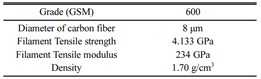
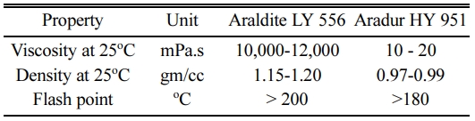
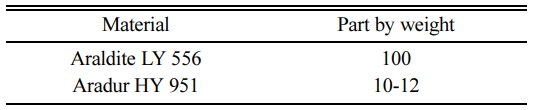
In the present work, carbon fiber of 600 GSM grade woven rowing material was used and its specifications are presented in Table 1. The fiber weight fraction was fixed as 40% with bi-directional orientation. Epoxy resin grade of LY556 was used with Hardner HY951 to form composite plate and the important properties of these materials are presented in Table 2. The mixing ratios of resin and hardener utilized for the work are shown in Table 3.
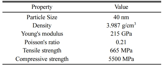
In the first step of fabrication, the Al2O3 nanoparticles were dispersed into acetone and mixed with the epoxy. Specifications of the Al2O3 powder are presented in Table 4. The mixtures thus prepared in different proportions were stirred with Ultrasonic cavitations (60% amplitude for about 30 min). In the next step, acetone was removed from the epoxy mixture by using vacuum oven (70 oC for 24 h). Lastly, the curing agent was added manually into the epoxy and stirred for 5-7 min. Then the uniform mixture of epoxy resin was applied on the carbon fiber surface. Slight pressure was applied on to the surface using a roller, to remove any air trapped as well as the surplus polymer present. Each laminate was cured for 24 h by hydraulic press under a pressure of 30 bar. The prepared composite was cut into sizes of 150 × 60 mm plates with a thickness of 3 mm.
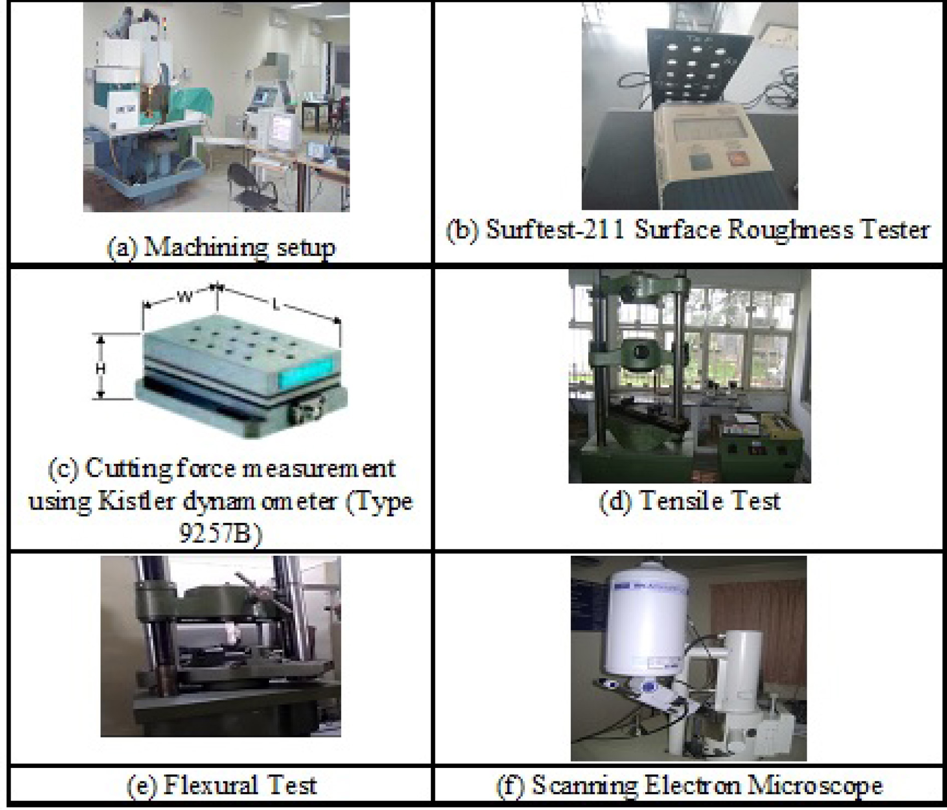
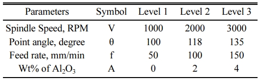
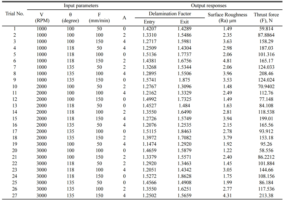
The drilling operations were carried out in the CNC vertical machining center - ARIX VMC 100 under dry conditions using HSS twist drill. The drilling parameters used in the study are provided in Table 5. In this work, L27 OA design was utilized to conduct the drilling experiments on the plates. The holes were photographed using CANON EOS 5D Mark III camera and the digital images analysed using CORELDRAW software. Ra and thrust force were measured by Mitutoyo surface roughness tester (Model: Surftest-211) and dynamometer (Kistler-9257B type) respectively and the instruments are shown in Fig. 1. And Table 6 presents the measured output responses. Delamination factor was calculated using the formula given below [22].
Where, Dmax is damaged diameter around the hole, Dactual is actual diameter to be drilled.
|
Fig. 1 Experimental setup and measurement of responses |
Taguchi based GRA is used to define the optimal drilling parameter combination for lower D-entry, D-exit, Ra and F in the drilling of CFRP [23]. The procedure of GRA is as follows [24]:
Initially the measured responses are normalized in the range of zero to one. In this study the considered responses have to be minimized, hence ‘the lower the better’ characteristic is used and specified as Equation (2)
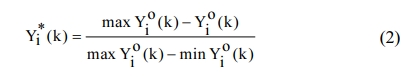
where Yi*(k) - normalized data, Yio(k) - original sequence, maxYio(k) - greatest value of Yio(k), and minYio(k) - lowest value of Yio(k).
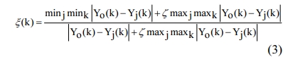
The grey relational coefficient (GRC) indicates the relation between the ideal and real experimental results. GRC is denoted as:
Where,
Distinguishing coefficient z is considered to be 0.5. The grey relational grade (GRG) was calculated by averaging the GRC equivalent to each feature. The GRG can be indicated as:
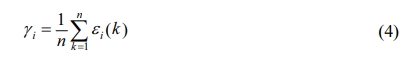
here, n is no. of responses.
Multi objective optimization
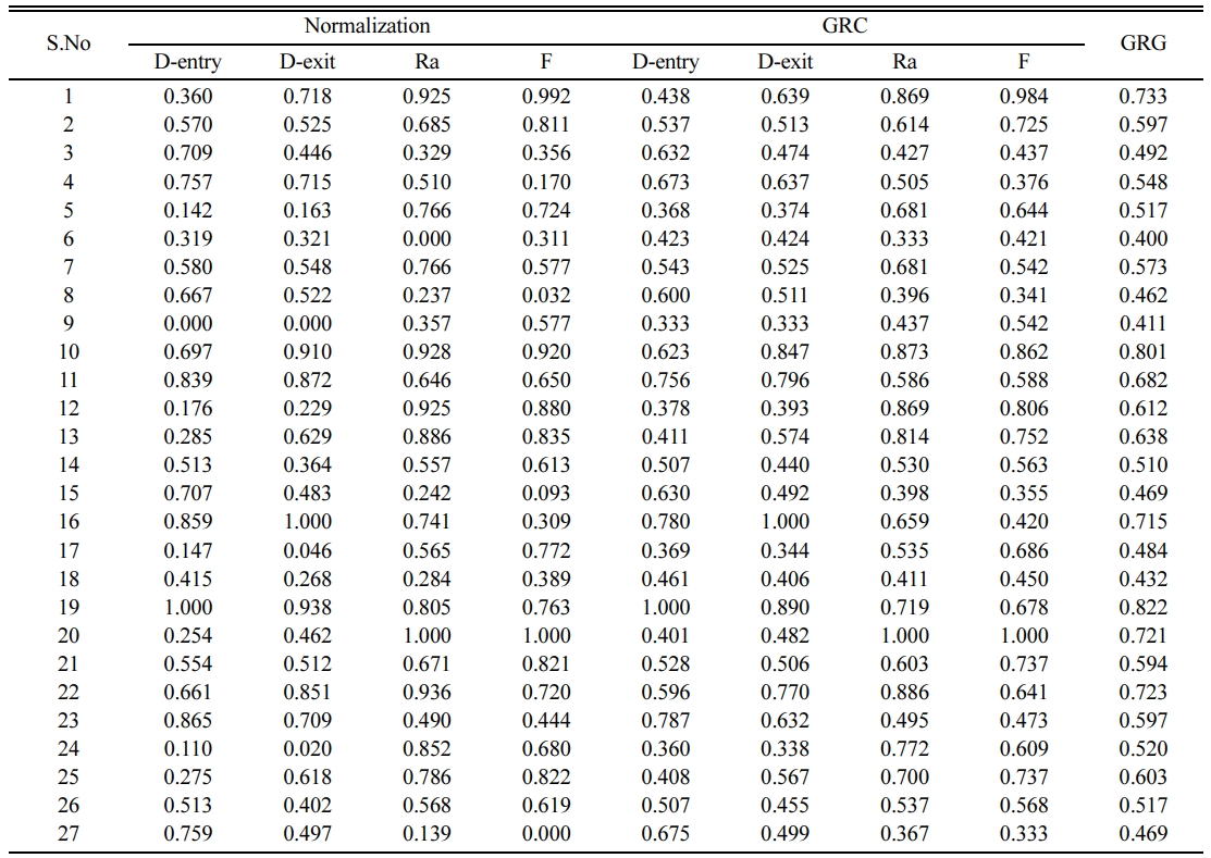
The aim of the optimization work is to minimize the D-Entry, D-Exit, Ra and F using Taguchi based GRA technique. Normalization values were calculated using Equation (2) and its plot is shown in Table 7. Equation (3) is used to compute the GRC values for all the output responses and presented in Table 7. Lastly the grey relational grade (GRG) was assessed by averaging the sum of GRCs by using Equation (4) and the values obtained are given in Table 4. The greater the GRG, it indicates that the quality characteristics are better. Trail 19 has the highest GRG value of 0.822 and it is the best multiple output response among the 27 runs [25].
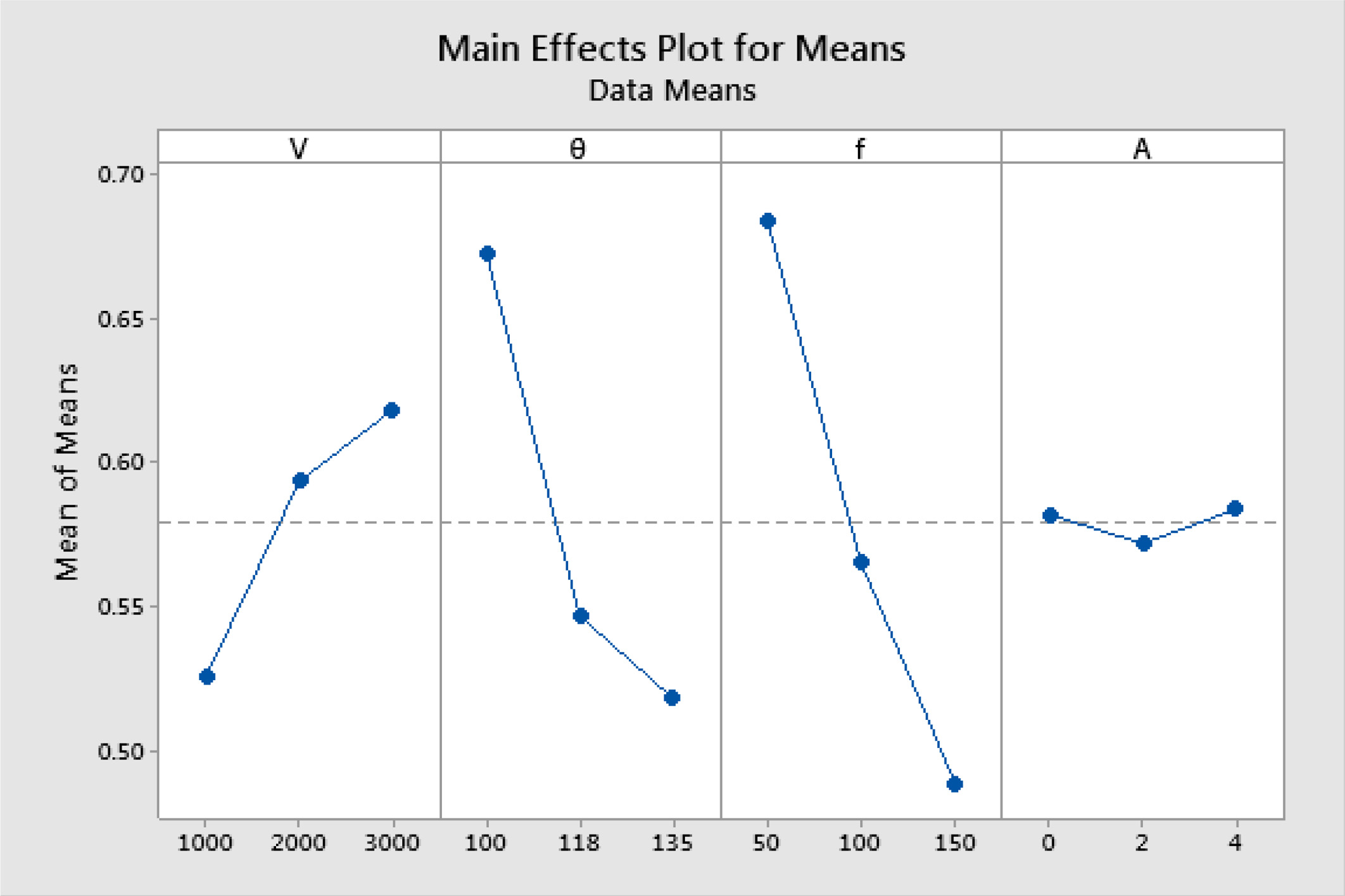
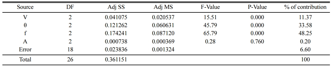
Based on the GRG response table (Table 8), the feed rate is found to be the foremost dominant factor on multiple performances followed by point angle, spindle speed and wt% of Al2O3. Consequently it was revealed that the drilling conditions of 3000 rpm spindle speed, 100° point angle, 50 mm/min (f) and 4 wt% of Al2O3 provide the optimal combination for drilling of CFRP composites. The main effects plot in Fig. 2 represents this.
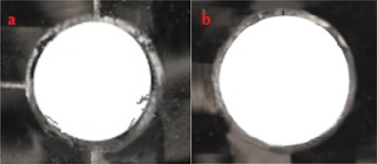
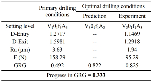
Table 9 indicates the validation experiment details and it assures that the results achieved through optimum set are better than that of trial results attained for the different combinations of input factors. Confirmation experiment illustrates that D-Entry is lowered from 1.2717 to 1.1469, D-Exit is decreased from 1.5981 to 1.2918, Ra is significantly reduced from 3.63 to 1.94 µm and thrust force is reduced from 158.29 N to 95.29 N by applying optimal combination. From the results, it is evident that multi objective optimization can be significantly simplified using this approach. Fig. 3(a) & (b) reveal the images of drilled holes at initial and optimum conditions. It is obvious from Fig. 3(b), that its delamination is lower than that of Fig 3(a).
The predicted GRG can be estimated by using the below equation [31]:
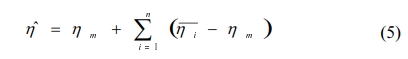
Where ηm is total mean of GRG, η is optimal level in each response
From the analysis of the results of this multi-objective system (from ANOVA Table 10), feed rate is found to be the most influential factor followed by point angle and spindle speed.
Effect of drilling parameters on responses
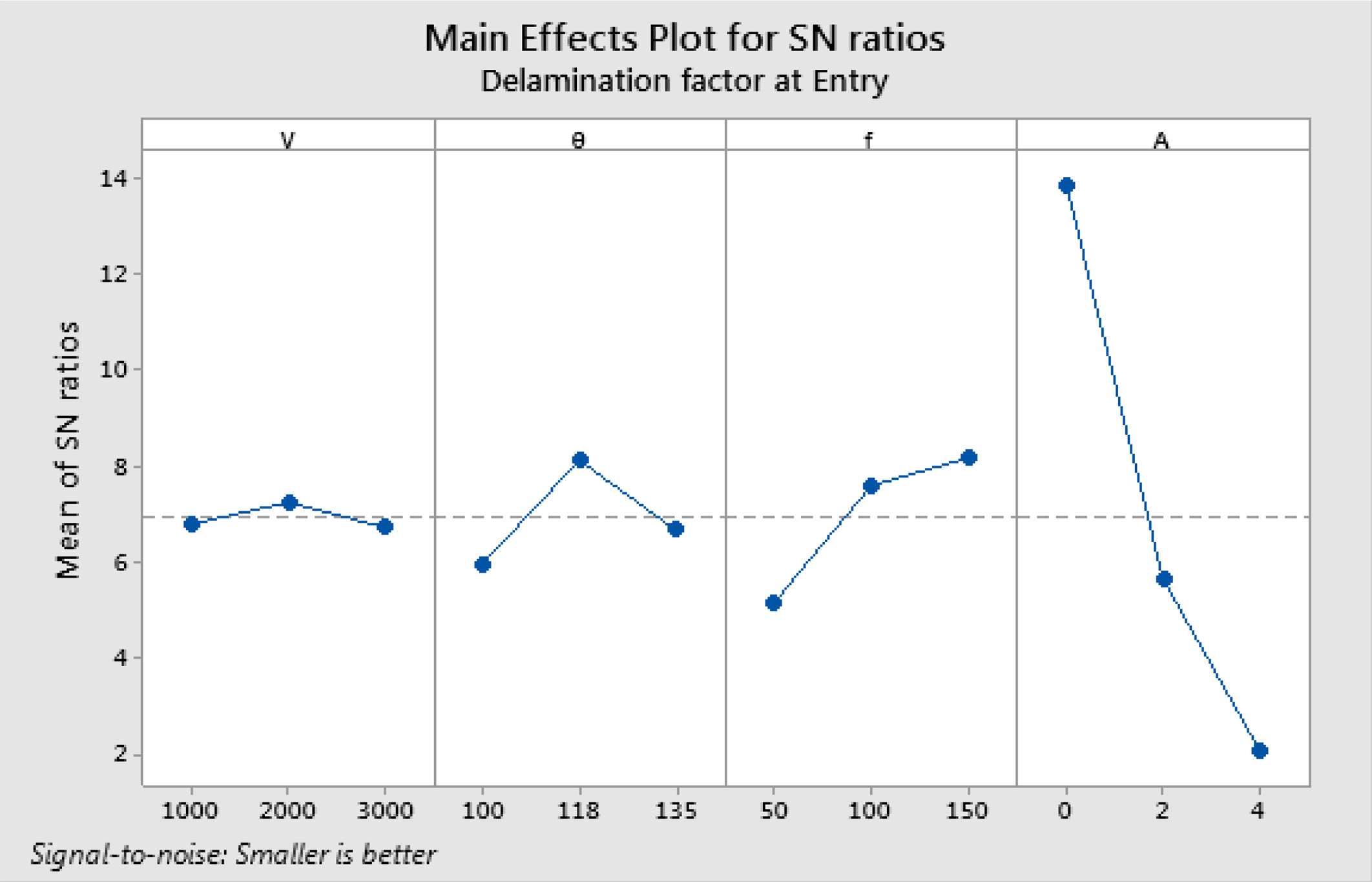
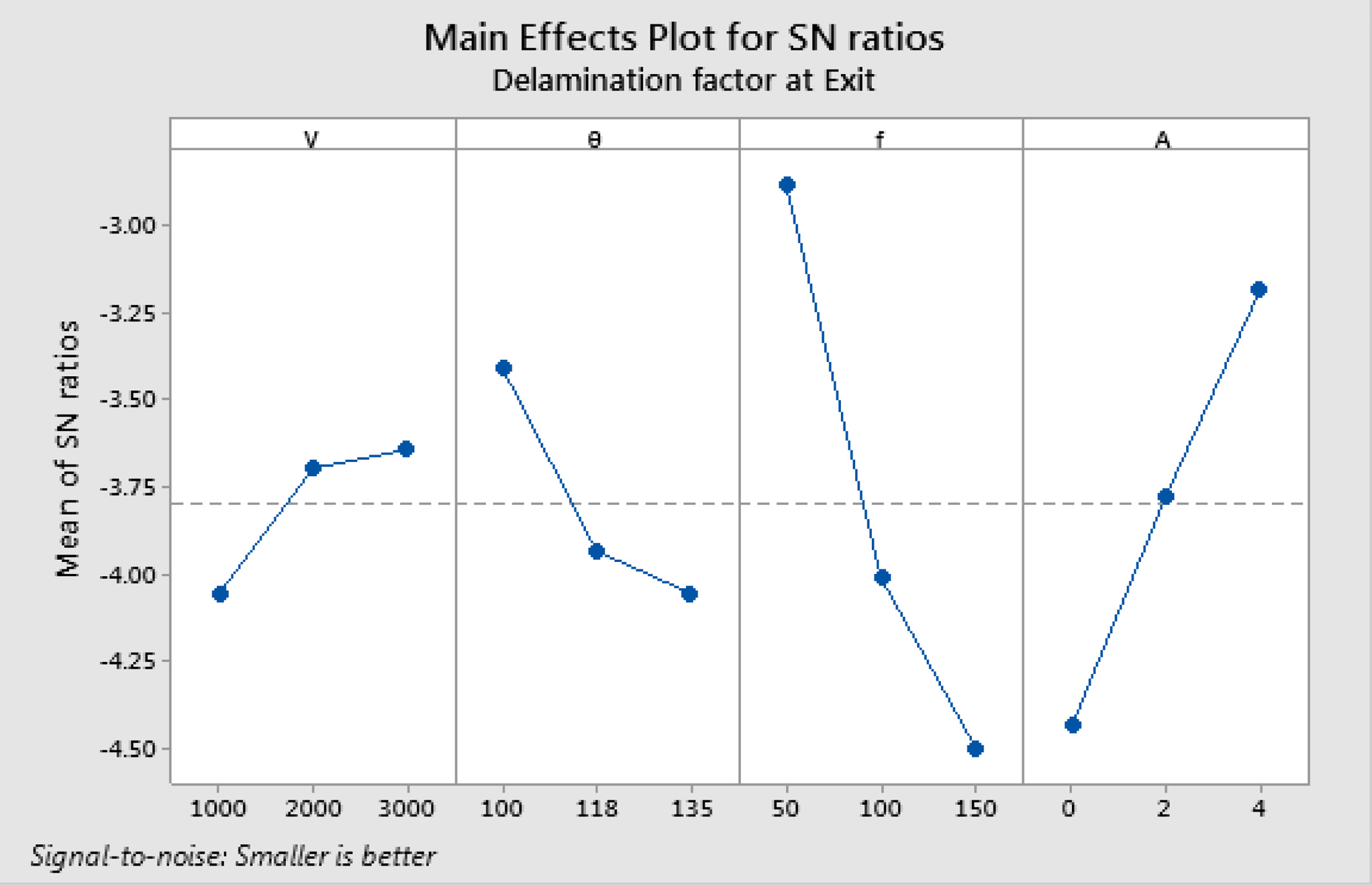
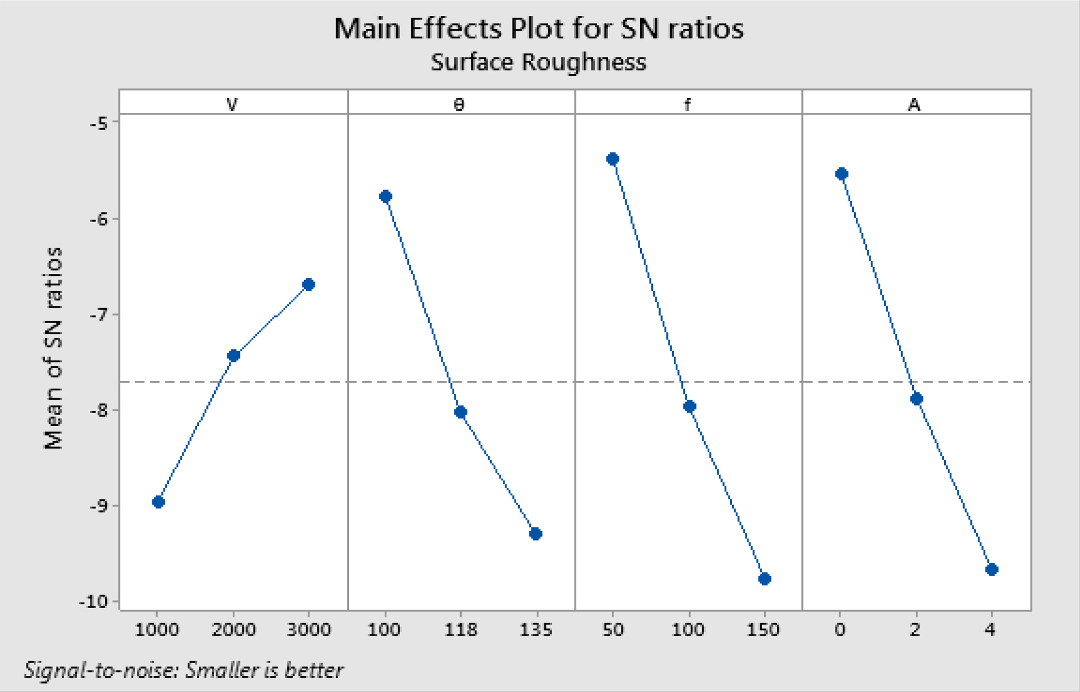
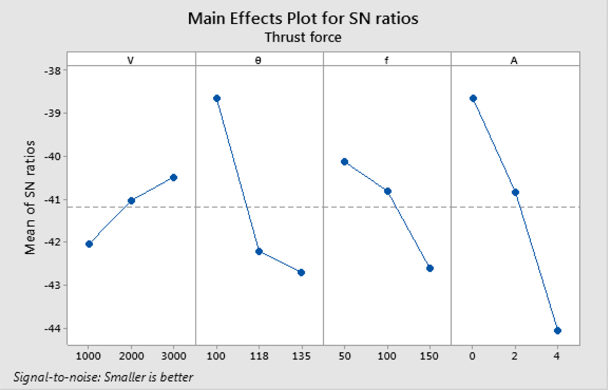
Figs. 4, 5, 6, and 7 denote the main effect plots for D-Entry, D-Exit, Ra and F respectively. The maximum S/N ratio of factor level assures the best conditions. Consequently it is noted from Fig. 4 and 5 that spindle speed at 3000 rpm, point angle at 100°, feed rate at 50 mm/min and incorporation of 4 wt% Al2O3 are the optimal conditions for obtaining lesser D-entry and D-exit. Fig. 4 & 5 also reveal that the D-entry and D-exit holes get enlarged with increase in feed rate while it gets decreased with raise in wt% of Al2O3. But spindle speed at 3000 rpm, point angle at 100°, feed rate at 50 mm/min and without incorporation of Al2O3 are found to be better combination to achieve lowest surface roughness and cutting force as exposed in Fig. 6 and 7.
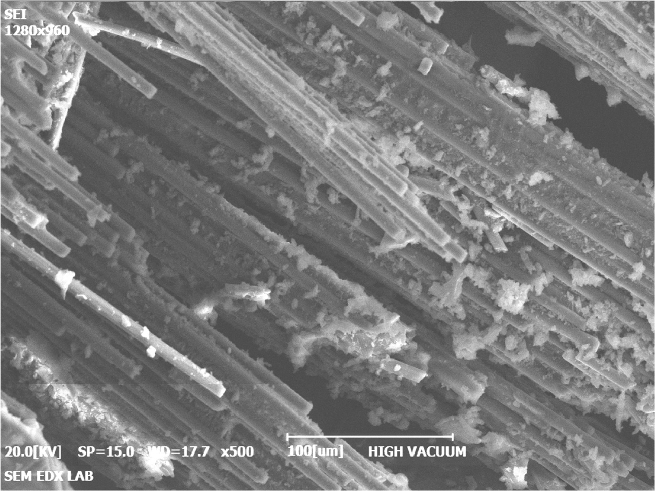
During the drilling of Hybrid CFRP composites, the force generated in the opposite direction of the drill results in separating each lamina from the other and thus produces the delaminated zone in the composite. This effect can be decreased by reducing the thrust force caused during drilling. Fig. 8 shows the micrograph of the drilled surface (at a magnification of 500´), in which the fractured fibers in the drilled surface of the composite can be seen clearly.
Analysis of variance
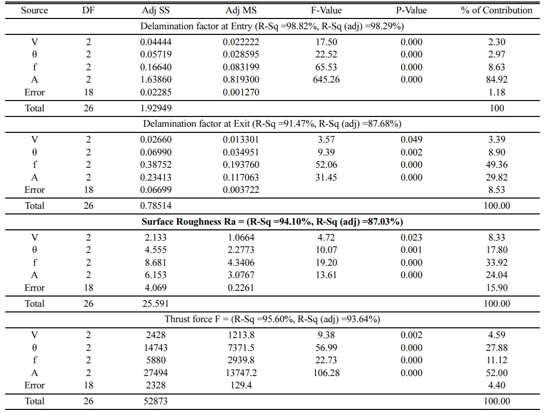
ANOVA is employed to find the significance and effect of each factor on D-Entry, D-Exit, Ra and F [30]. From the analysis, it was observed that reinforcement wt.% has the maximum influence on D-entry (84.92%). The feed has the highest influence on in D-exit (49.36) followed by reinforcement wt.%. Feed rate has maximum influence on Ra (33. 92%) followed by reinforcement wt.%. Reinforcement wt. % has utmost influence on F (52%) followed by point angle. As the strength of the composite increases with the increase of wt% of Al2O3, more force is required to drill them, hence the increase in the thrust force. Among the drilling parameters considered, spindle speed is the least influencing factor. From Table 11, it is obvious that R2 values are almost closer to unity and the deviation with adj. R2 is also least which indicates the importance of the developed model.
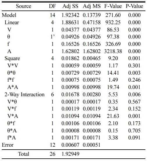
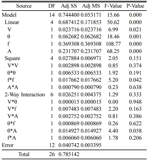
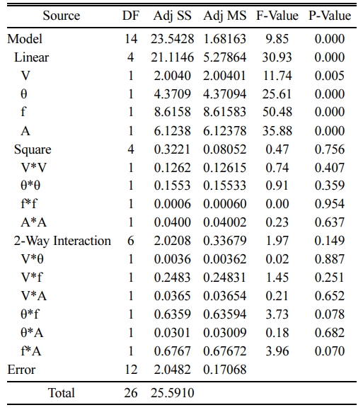
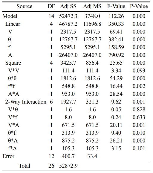
The second order quadratic regression models for D-entry, d-exit, surface roughness and thrust force were developed through RSM [26, 29]. Additionally, ANOVA for the output response are shown in Tables 12, 13, 14 and 15. Based on the results obtained from the drilling operations conducted on CFRP composites the equations obtained for D-entry, D-exit, Ra and F depending on the input parameters are as follows.
Delamination factor at Entry
= 2.268 + 0.000002 V - 0.02919 θ - 0.00209 f
+ 0.1328 A - 0.000000 V*V + 0.000114 θ*θ
+ 0.000004 f*f - 0.01020 A*A + 0.000000 V*θ
+ 0.000000 V*f + 0.000017 V*A - 0.000012 θ*f
+ 0.000083 θ*A + 0.000138 f*A (6)
Delamination factor at Exit
= -0.61 - 0.000173 V + 0.0298 θ + 0.00525 f
+ 0.1119 A + 0.000000 V*V - 0.000108 θ*θ
- 0.000022 f*f + 0.00287 A*A + 0.000000 V*θ
+ 0.000001 V*f - 0.000009 V*A + 0.000011 θ*f
- 0.001163 θ*A - 0.000259 f*A (7)
Ra = -6.07 - 0.00038 V + 0.127 θ - 0.0199 f
+ 0.357 A + 0.000000 V*V - 0.000526 θ*θ
- 0.000004 f*f - 0.0204 A*A - 0.000001 V*θ
- 0.000003 V*f - 0.000032 V*A + 0.000304 θ*f
- 0.00165 θ*A + 0.00274 f*A (8)
Thrust force
= -692 - 0.0209 V + 13.58 θ - 1.246 f - 21.33 A
+ 0.000004 V*V - 0.05681 θ*θ + 0.003825 f*f
+ 3.151 A*A + 0.000024 V*θ - 0.000019 V*f
- 0.004319 V*A + 0.00675 θ*f + 0.2817 θ*A
+ 0.0342 f*A (9)
R2 and predicted R2 values of the second order quadratic models are: D-entry (R2 = 99.69% & R2 (pred) = 99.31%), D-exit (R-Sq = 94.81% & R-Sq (pred) = 88.76%), Ra (R2= 92.00% & R2 (pred) = 82.66%), Ra (R2= 99.24% & R2 (pred) = 94.79%). Deviation between R2 and predicted R2 is negligible (within 5%) for each regression model enlightens for precise prediction capability of the constructed models.
Tensile and flexural test
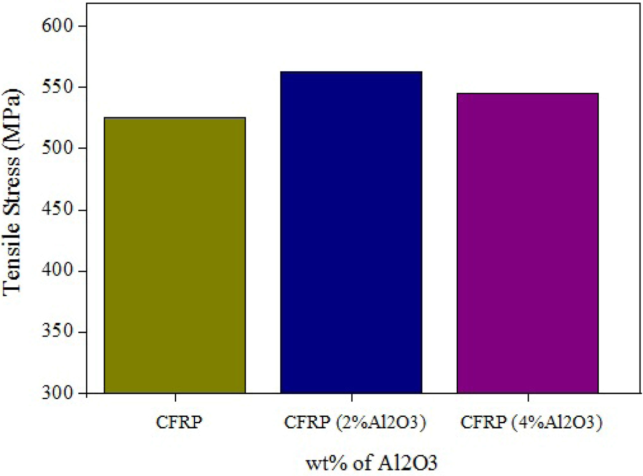
It is obvious from Fig. 9 that with an increase in wt% of alumina in the epoxy matrix, the tensile strength (TS) increases up to a maximum value and decreases consequently for higher concentration due to the agglomerations of nanoparticles [27]. It is observed that CFRP composite with 2% Al2O3 revealed more TS compared to others.
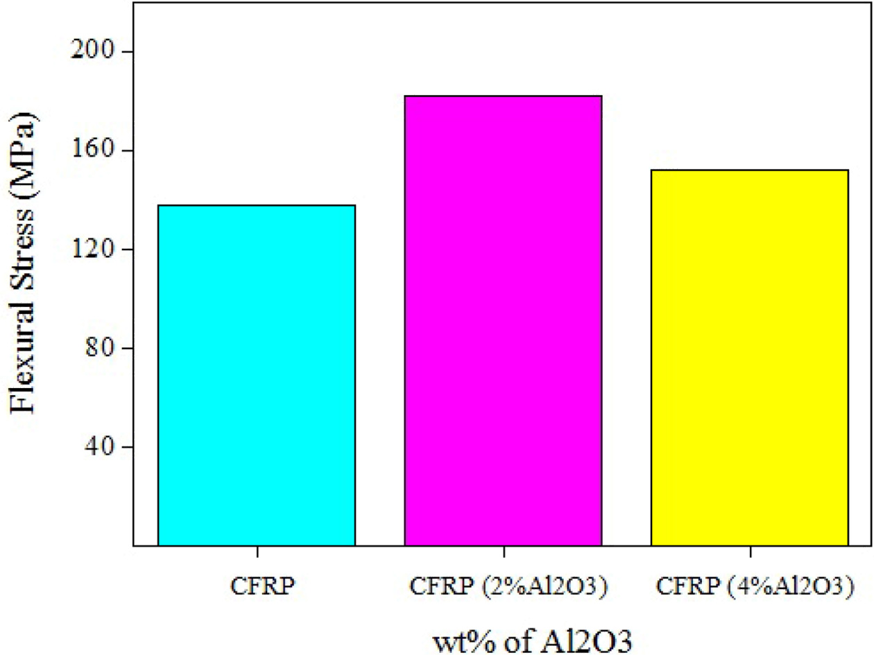
The three point bend test is conducted on CFRP composite samples as per ASTM D790 standard. The size of the specimen was 200 mm ×12.7 mm × 3 mm with a length of 50 mm and 1.5 mm/min cross head-speed maintained for the test. It is obvious from Fig. 10 that with an increase in wt% of Al2O3 in the epoxy matrix, the flexural strength (FS) increases up to an inclusion of 2% concentration and gets reduced afterward for 4 wt% of Al2O3 due to nanoparticle agglomerations. The enhanced FS was due to the better dispersion of Al2O3 nanoparticle in the epoxy matrix and at greater concentration, aggregation of Al2O3 naonoparticles occurs which decreases the FS of the composites [28].
|
Fig. 2 Main effect plot for GRG |
|
Fig. 3 Drilled hole at initial and optimal condition. |
|
Fig. 4 S/N ratio plot for D-Entry. |
|
Fig. 5 S/N ratio plot for D-Exit. |
|
Fig. 6 S/N ratio plot for Ra. |
|
Fig. 7 S/N ratio plot for thrust force. |
|
Fig. 8 SEM micrograph of drilled surface. |
|
Fig. 9 TS with increase in wt% of Al2O3. |
|
Fig. 10 FS with increase in wt% of Al2O3 |

CFRP composite was fabricated with the incorporation of Al2O3 particles through hand layup technique. The drilling tests were carried out on the basis of L27 OA and the optimal conditions were found for lowest delamination, surface roughness and thrust force. Second order quadratic models were developed for all responses through regression analysis.
The most influencing factor attained from GRA is feed rate followed by point angle whereas the reinfor- cement weight % shows least influence. The results of GRA show that spindle speed (3000rpm), point angle (100o), feed (50 mm/min) and reinforcement weight % (wt%4) of Al2O3 would lead to lowest value of D-entry, D-exit, Ra and F. The suggested optimum parameter combination provides the outcome of 1.1469 D-entry, 1.2918 D-exit, 1.94 μm Ra and 95.29N thrust force. From ANOVA study, it can be concluded that reinforcement wt% (Al2O3) has the dominant effect on D-entry and thrust force whereas feed rate has significant effect on D-exit and Ra. The inclusion of up to 2 wt% concen- tration of Al2O3 in the composite increased both, the tensile and flexural strengths whereas further rise in concentration reduced the strengths due to nanoparticle agglomerations.
- 1. P.E. Faria, J.C. Campos Rubio, A.M. Abrao, and J.P. Davim, J. Reinf. Plast. Compos. 28[19] (2009) 2353-2363.
-

- 2. R. Stone and K. Krishnamurthy, Int. J. Mac. Tools. Manuf. 36[9] (1996) 985-1003.
-
- 3. L.M.P. Durao, D.J.S. Goncalves, J.M.R.S. Tavares, V.H.C. de Albuquerque, A.A. Vieria, and A.T. Marques, Comp. Struct. 92[7] (2010) 1545-1550.
-
- 4. B. Ravi Sankar, P. Umamaheswarrao, A.V. Avinash Reddy, and P. Koushik Kumar, J. Bas. App. Eng. Res. 1[3] (2014) 19-24
- 5. S.O. Ismail, H.N. Dhakal, I. Popov, and J. Beaugrand, Eng. Sci. Technol. Int. J. 19[4] (2016) 2043-2052.
-
- 6. Y. Turki, M. Habak, R. Velasco, Z. Aboura, K. Khellil, and P. Vantomme, Int. J. Mach. Tools. Manuf. 87 (2014) 61-72.
-
- 7. D.F. Liu, Y.J. Tang, and W.L. Cong, Compos. Struct. 94[4] (2012) 1265-1279.
-
- 8. R. Baptista, A. Mendao, M. Guedes, and R.M. Mendes, Procedia Struc Integrity 1 (2016) 74-81.
-
- 9. T. Rajmohan, Int. J. Part. Sci. Technol. 37[1] (2016) 21-30.
-
- 10. S.R. Ranganatha and V.S. Ramamurthy, Int. J. Adv. Eng. Technol. 4[3] (2013) 105-107.
- 11. V. Krishnaraj, A. Prabukarthi, A. Ramanathan, N. Elanghovan, M. Senthil Kumar, R. Zitoune, and J.P. Davim, Composites 43[4] (2012) 1791-1799.
-
- 12. H. Zhang, W. Chen, D. Chen, and L. Zhan, Key Eng. Mater. 196 (2001) 43-52.
-
- 13. U. Heisel and T. Pfeifroth, Proc CIRP 1 (2012) 471-476.
-
- 14. L.M.P. Durao, D.J.S. Goncalves, J.M.R.S. Tavares, V.H.C. Albuquerque, and A. de Torres Marques, in Proceedings of the 14th European conference on composite materials, June 2010, (Budapest University, 2010) p.1-10.
- 15. A. Krishnamoorthy, S. Rajendra Boopathy, K. Palanikumar, and J. Paulo Davim, Measurement 45[5] (2012) 1286-1296.
-
- 16. S. Aravind, K. Shunmugesh, J. Biju, and J.K. Vijayan, Mater. Today: Procee 4[2] (2017) 4188-4195.
-
- 17. K. Abhishek, S. Datta, and S.S. Mahapatra, Int. J. Adv. Manuf. Technol. 76[1-4] (2015) 401-416.
-
- 18. M.P. Jenarthanan and N. Naresh, Ind. J. Eng. Mat. Sci. 22 (2015) 313-320.
- 19. A. Noorul Haq, P. Marimuthu, and R. Jeyapaul, Int. J. Adv. Manuf. Technol. 37[3-4] (2008) 250-255.
-
- 20. R. Viswanathan, S. Ramesh, S. Maniraj, and V. Subburam, Measurement 159 (2020) 107800.
-
- 21. G. Anand, N. Alagumurthi, R. Elansezhian, K. Palanikumar, and N. Venkateshwaran, J. Braz. Soci. Mech. Sci. Eng. 40[4] (2018) 214.
-
- 22. W.C. Chen, Int. J. Mach. Tools. Manuf. 37[8] (1997) 1097-1108.
-
- 23. J. Lin and C. Lin, Int. J. Mach. Tools. Manuf. 42[2] (2002) 237-244.
-
- 24. D. Julong, J. Grey System 1[1] (1989) 1-24.
- 25. S. Ramesh, R. Viswanathan, and S. Ambika, Measurement, 78 (2016) 63-72.
-
- 26. R. Viswanathan, S. Ramesh, N. Elango, and D.K. Kumar, Pert. J. Sci. Technol. 25[1] (2017) 255-262.
- 27. H.B Kaybal, Hasan Ulus, and A.V.C Ahmet, Int. J. Inno. Res. Sci. Eng. Technol. 5[12] (2016) 75-79.
- 28. A. Mohanty and V.K. Srivastava, Fib. Poly. 16 [1] (2015) 188-195.
-
- 29. T. Pridhar, K. Ravikumar, B. Sureshbabu, R. Srinivasan, and B. Sathishkumar, Int. J. Ceram. Process. Res. 21[2] (2020) 131-142.
-
- 30. C. Chanakyan and S. Sivasankar, Int. J. Ceram. Process. Res. 21[6] (2020) 647-655.
-
- 31. Y.C. Lin, J.C. Hung, H.M. Chow, and A.C. Wang, Int. J. Ceram. Process. Res. 16[2] (2015) 249-257.
 This Article
-
2021; 22(3): 345-355
Published on Jun 30, 2021
- 10.36410/jcpr.2021.22.3.345
- Received on Nov 3, 2020
- Revised on Feb 9, 2021
- Accepted on Mar 2, 2021
Services
- Abstract
introduction
materials and methods
optimization methodology
result and discussion
conclusions
- References
- Full Text PDF
Shared
Correspondence to
- M. Srinivasan
-
Research Scholar, Anna University Chennai, India
Tel : ++919443084485 - E-mail: m75sri@gmail.com
Clean-Energy Research Institute(CRI), Hanyang University, 222, Wangsimni-ro, Seongdong-gu, Seoul, 04763, Korea
E-mail: jcpr@hanyang.ac.kr