


- Significantly improving electrochemical performances of TiO2 coated LiNi0.8Co0.1Mn0.1O2 cathode
Jae-Soo Shin and Seung-Hwan Lee*
Department of Advanced Materials Engineering, Daejeon University, Daejeon 34520, Korea
This article is an open access article distributed under the terms of the Creative Commons Attribution Non-Commercial License (http://creativecommons.org/licenses/by-nc/4.0) which permits unrestricted non-commercial use, distribution, and reproduction in any medium, provided the original work is properly cited.
In this paper, we successfully synthesized Ti-coated Ni-rich LiNi0.8Co0.1Mn0.1O2 cathode and microstructure and electrochemical performances for high-energy lithium-ion battery are investigated. The TiO2-coated LiNi0.8Co0.1Mn0.1O2 delivers excellent cation mixing and there is no big difference in morphology between pristine and TiO2 coated LiNi0.8Co0.1Mn0.1O2. The TiO2-coated LiNi0.8Co0.1Mn0.1O2 has higher electrochemical performances (initial discharge capacity : 201.3 mAh g-1, rate capability : 90.5% at 4.0 C and cyclability : 79.4% after 100 cycles). It can be explained by the positive role of TiO2 layer on the surface of LiNi0.8Co0.1Mn0.1O2
Keywords: Ti-coated Ni-rich layered LiNi0.8Co0.1Mn0.1O2, microstructure, cation mixing, higher electrochemical performances, TiO2 layer
Recently, lithium ion batteries (LIBs) are used to electric vehicles (EVs), hybrid electric vehicles (HEVs) and energy storage systems [1-3]. LIBs are required to meet high energy, long cycle life, specific capacity, stability and low cost [4-5]. Until now, LiCoO2 (LCO) is used to the cathode materials of LIBs due to stable discharge plateau and excellent reversibility. However, LCO have some shortcomings such as poor thermal stability, high costs and environmental pollution [6-7].
Hence, LCO need to be replaced by LiNixCoyMnzO2. Compared with LCO, NCM have various advantages of good thermal stability, low cost and eco-friendly [6-7]. Also, high-Ni content of LiNixCoyMnzO2 has excellent reversible specific capacity compared to low-Ni content LiNixCoyMnzO2, which is helpful for commercialization [8-9]. Unfortunately, high-Ni content of NCM (Ni-rich NCM) have poor cycle performance and low coulombic efficiency. This is because, i) the cation mixing is caused by similar radius between Ni2+ (0.69 Å) and Li+ (0.76 Å) and ii) structural instability due to oxygen release from the crystal lattice [10-11]. To solve the problems, effective strategies such as coating and doping are widely used [12-15].
In this paper, we successfully prepared TiO2 coated LiNi0.8Co0.1Mn0.1O2 and investigated the electrochemical performances. The TiO2 coated LiNi0.8Co0.1Mn0.1O2 can improve electrochemical performance and structure stability.
Spherical LiNi0.8Co0.1Mn0.1O2 powders were synthesized by using co-precipitation method. The Ni0.8Co0.1Mn0.1(OH)2 precursor was prepared using NiSO4·6H2O, CoSO4·7H2O, MnSO4·H2O, Na2CO3 and NH3·H2O.Precipitating agentwas prepared using the NaOH and NH4OH solution. The spherical Ni0.8Co0.1Mn0.1(OH)2 precursor mixedwith LiOH·H2O in a molar ratio 1.05 : 1. Subsequently, the mixture was preheated at 500 oC for 5 h and then calcined750 C for 15 h in tube furnace under the oxygen flow. The TiO2 coating layer wasformed on the surface of LiNi0.8Co0.1Mn0.1O2 by the hydroxylation of titanium tetrabutoxide (TBOT) in a mole ratio of Ti:NCM = 0.03 : 1. After that, the sample was sintered at 600 oC for 3 h in air.
The cathode was fabricated by cathode powder (96 wt.%), conductive carbon black (2 wt.%) and poly- vinylidene fluoride (PVDF) (2 wt.%). After that, to form slurry, N-methyl-pyrrolidinone (NMP) solvent was added. Aluminum foil coated on the prepared slurry and then dried at 120 oC for 10 h in a vacuum oven. The CR 2032 coin cells were assembled using lithium foil as an anode in glove box filled with argon gas. 1 M LiPF6 in ethylene carbonate (EC), dimethyl carbonate (DMC) and ethyl methyl carbonate (EMC) (with a volumetric ratio 1 : 1 : 1) were used to electrolyte.
The X-ray diffraction (XRD, X'pert MPD DY1219) was used to measure the structural properties of samples. The field emission scanning electron microscopy (FE-SEM, Hitachi S-4800) was prepared to confirm the morphology of the TiO2 coated sample. An equipment (TOSCAT-3100, Toyo system) was adopted to measure the electrochemical performances.
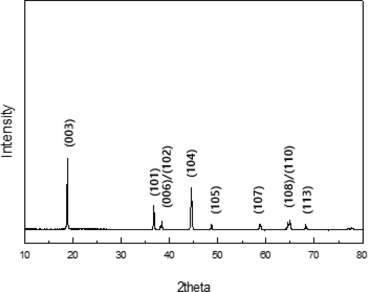
Fig. 1 presents the XRD patterns recorded on TiO2 coated LiNi0.91Co0.06Mn0.03O2. It was observed that there is no significant change in peak position and shape of the XRD via TiO2 coating. This is because the coating does not affect the LiNi0.91Co0.06Mn0.03O2 structure [16]. The XRD pattern of sample demonstrates that TiO2 coated LiNi0.91Co0.06Mn0.03O2 can be identified by a typical structure of layered hexagonal α-NaFeO2 structure with the space group R-3m. The clear peak splits corresponding to Miller indices of (006)/(102) and (108)/(110) are observed and it indicates the formation of well-crystallized hexagonal layered structure of LiNi0.91Co0.06Mn0.03O2 [17]. The I(003)/I(104) ratio of the TiO2 coated LiNi0.91Co0.06Mn0.03O2 is 1.56, which is sufficiently higher than 1.2, which is the standard for cation mixing degree. It means superior structure stability and cation ordering of TiO2 coated LiNi0.91Co0.06Mn0.03O2.
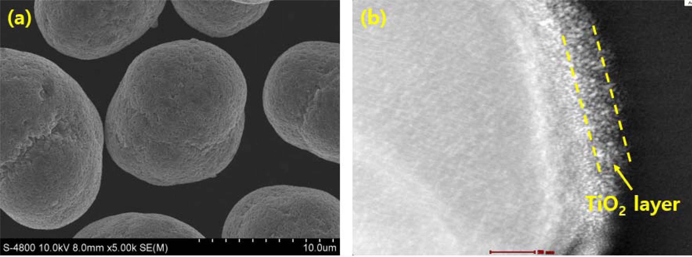
Fig. 2 illustrates the (a) FESEM and (b) TEM images of the TiO2 coated LiNi0.91Co0.06Mn0.03O2. We can confirm that the TiO2 coated LiNi0.91Co0.06Mn0.03O2 shows spherical granule shape with an average size of 12.0 μm, consisting of numerous primary particles of approximately 150 -450 nm. The primary particles contacted each other directly, which can reduce the electrical resistance, thus, it has a positive effect on the electrochemical performance. From FESEM image, it is clearly seen that TiO2 coating does not change the spherical shape of pristine LiNi0.91Co0.06Mn0.03O2 [18]. Fig. 2(b) exhibits the TiO2 coating layer. The average thickness of TiO2 coating layer is approximately 12 nm. Based on structural properties of TiO2 coated LiNi0.91Co0.06Mn0.03O2, we can infer that TiO2 coated LiNi0.91Co0.06Mn0.03O2 could deliver excellent electrochemical performances.
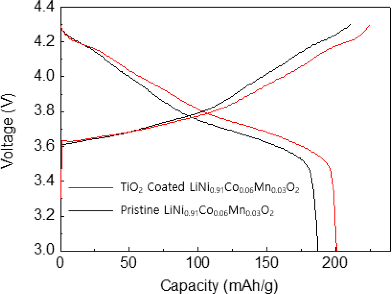
To investigate the electrochemical tests of TiO2 coated LiNi0.91Co0.06Mn0.03O2, the loading level of the sample was adjusted about 14.6 mg/cm2 because the high areal capacity is necessary for practical application of lithium ion batteries [19]. Fig. 3 shows the initial charge-discharge curves of TiO2 coated LiNi0.91Co0.06- Mn0.03O2 in a potential range of 3.0 - 4.3 V at 0.5 C. The TiO2 coated LiNi0.91Co0.06Mn0.03O2 has a typical charge-discharge behavior. There is no noticeable additional plateau. It indicates that the TiO2 coating does not affect the electrochemical activity of the LiNi0.91Co0.06Mn0.03O2. The TiO2 coated LiNi0.91Co0.06- Mn0.03O2 has a discharge capacity of 201.3 mAh g-1, which is higher value compared to pristine sample, resulting from electronically conductive TiO2 layer [20]. It can be explained by the enhanced conductivity of LiNi0.91Co0.06Mn0.03O2.
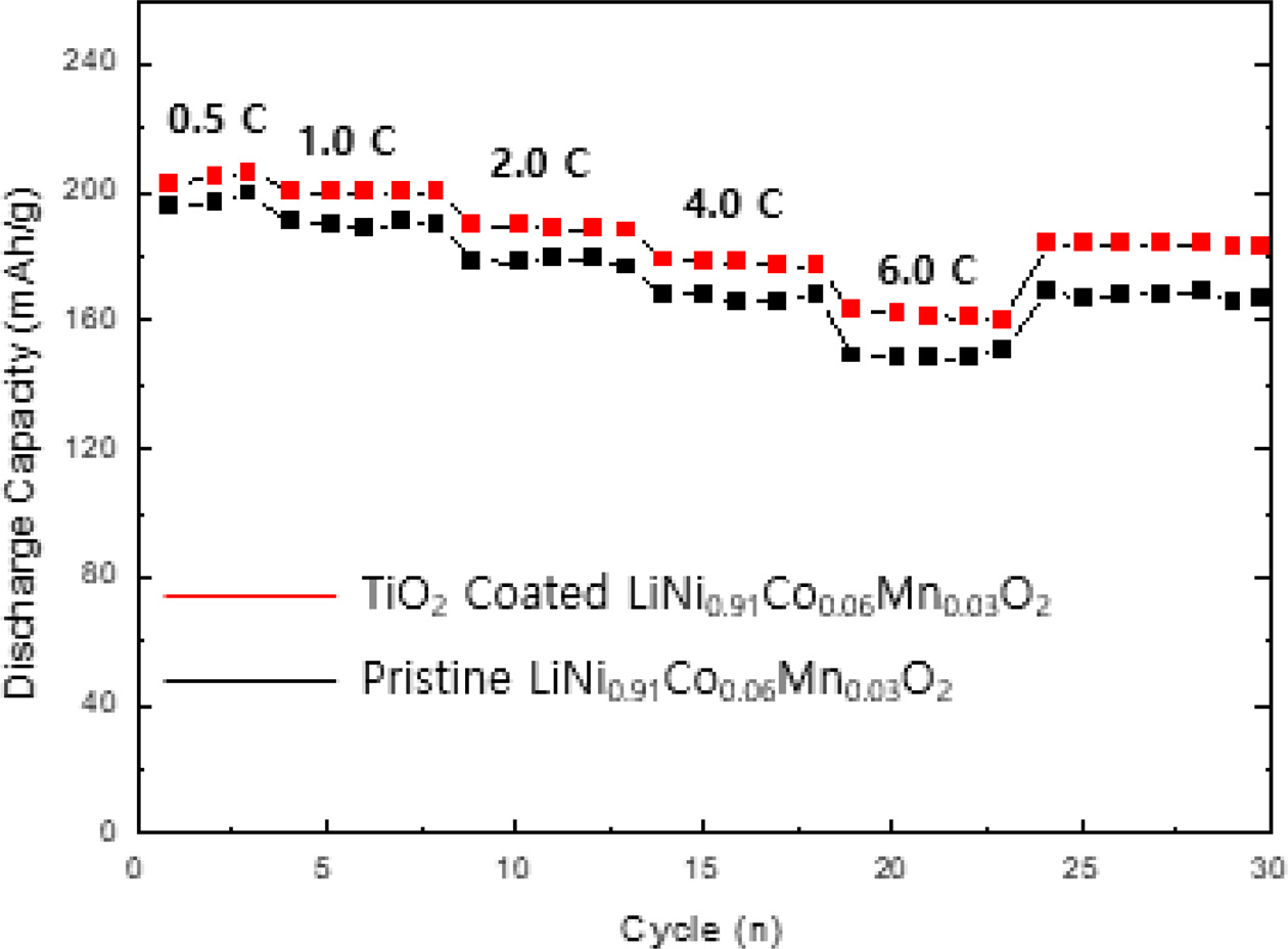
Fig. 4 shows the rate performance of TiO2 coated LiNi0.91Co0.06Mn0.03O2 at various C-rates from 0.1 C to 4.0 C. It is obvious that the capacity retention of TiO2 coated LiNi0.91Co0.06Mn0.03O2 proportionally decreases with increasing the C-rate. The capacity retention slightly decrease at low C-rates (0.5 and 1.0 C) while the retention of sample is decreased relatively largely at high C-rates (2.0 and 4.0 C). It is associated with the low electrical resistance of TiO2 coated LiNi0.91Co0.06Mn0.03O2, leading to rapid lithium ion transfer [21].
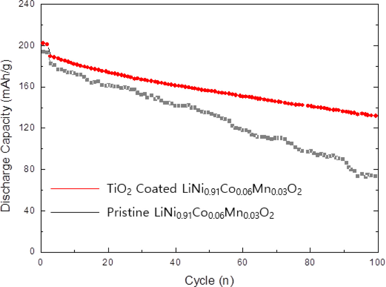
Fig. 5 shows the long-term cycle performance of TiO2 coated LiNi0.91Co0.06Mn0.03O2 at 0.5 C rate at 25 oC in the voltage range 3.0 and 4.3 V. The capacity is inversely proportional to the cycle number. However, the TiO2 coated LiNi0.91Co0.06Mn0.03O2 shows the excellent cycle retention than previously reported pristine sample. The capacity retention of TiO2 coated LiNi0.91Co0.06- Mn0.03O2 is 79.4% after 100 cycles. It is closely associated with the contribution of TiO2 layer, suppressing the formation of a resistive solid electrolyte interphase (SEI) layer [22]. It causes the increase in charge transfer resistance at the interface between electrolyte and TiO2 coated LiNi0.91Co0.06Mn0.03O2 cathode. More importantly, TiO2 layer can alleviate the transition metal elution of LiNi0.91Co0.06Mn0.03O2 cathode to maintain the original layered structure/stable surface chemistry during electro- chemical cycling. It was reported that crystalline/amorphous TiO2 layer can be formed on the surface of LiNi0.91Co0.06Mn0.03O2. Therefore, the protective/con- ductive TiO2 layer can suppress the negative unwanted reaction between electrolyte and LiNi0.91Co0.06Mn0.03O2, leading to structural degradation and gassing [23, 24]. It is resulting from O2 release and electrolyte decay. These phenomenon can be explained by strong bond dissociation energy of Ti-O compared to those of other transition metal ions-O. Moreover, it is well known that coating layer has a positive effect on phase transition (H2→H3) and micro-cracking, which are considered important factors of capacity fading [22, 25].
|
Fig. 1 XRD patterns of TiO2 coated LiNi0.91Co0.06Mn0.03O2. |
|
Fig. 2 (a) FESEM image and (b) TEM image of TiO2 coated LiNi0.91Co0.06Mn0.03O2. |
|
Fig. 3 Initial charge-discharge curves of TiO2 coated LiNi0.91Co0.06Mn0.03O2. |
|
Fig. 4 Rate capability of TiO2 coated LiNi0.91Co0.06Mn0.03O2. |
|
Fig. 5 Cycle performance of TiO2 coated LLiNi0.91Co0.06Mn0.03O2. |
We successfully formed TiO2 coating layer on the surface of LiNi0.91Co0.06Mn0.03O2 cathode via solid-state reaction. The TiO2 coated LiNi0.91Co0.06Mn0.03O2 cathode shows not only good structural stability but also superior electrochemical performances. The well-crystallized TiO2 coated LiNi0.91Co0.06Mn0.03O2 cathode maintain original XRD pattern and microstructure of pristine sample. The electrochemical performances of TiO2 coated LiNi0.91Co0.06Mn0.03O2 cathode surpass pristine sample. It is elucidated that TiO2 layer could decreases the cation disordering and plays a crucial role in physical on the surface of LiNi0.91Co0.06Mn0.03O2. As a result, it can be concluded that TiO2 coating layer can be regarded as a breakthrough for high performance and stability LiNi0.91Co0.06Mn0.03O2 cathode.
- 1. J.W. Seok, J. Lee, T. Rodgers, D.H. Ko, and J.H. Shim, Trans. Electr. Electron. Mater. 20[6] (2019) 548-553.
-

- 2. T.T. Kojima, T. Ishizu, T. Horiba, and M. Yoshikawa, J. Power Sources. 189[1] (2009) 859-863.
-
- 3. Y. Xi, Y. Liu, D. Zhang, S. Jin, R. Zhang, and M. Jin, Solid State Ion. 327 (2018) 27-31.
-
- 4. C.C. Qin, J.L. Cao, J. Chen, G.L. Dai, T.F. Wu, Y. Chen, Y.F. Tang, A.D. Li, and Y. Chen, Dalton Trans. 45[23] (2016) 9669-9675.
-
- 5. Y. Mo, L. Guo, H. Jin, B. Du, B. Cao, Y. Chen, D. Li, and Y. Chen, J. Power Sources. 448 (2020) 227439.
-
- 6. M. S. Islam, R. A. Davies, and J. D. Gale, Chem. Mater. 15[22] (2003) 4280-4286.
-
- 7. F. Lin, L.M. Markus, D. Nordlund, T.C. Weng, M.D. Asta, H.L. Xin, and M.M. Doeff, Nat. Commun. 5[1](2014) 1-9.
-
- 8. A. Manthiram, J.C. Knight, S.T. Myung, S.M. Oh, and Y.K. Sun, Adv. Energy Mater. 6[1] (2016) 1501010.
-
- 9. X. Zhao, L. An, J. Sun, and G. Liang, J. Electroanal. Chem. 810[1] (2018). 1-10.
-
- 10. X. Zhang, W.J. Jiang, A. Mauger, F. Gendron, and C.M. Julien, J. Power Sources. 195[5] (2010) 1292-1301.
-
- 11. I.M. Makus, F. Lin, K.C. Kam, M. Asta, and M.M. Doeff, J. Phys. Chem. Lett. 5[21] (2014) 3649-3655.
-
- 12. L. Yao, F. Liang, J. Jin, B.V.R. Chowdari, J. Yang, and Z. Wen, Chem. Eng. J. 389 (2020) 124403.
-
- 13. W. Li, Y. Li, L.S. Yang, Y.X. Chen, J. Guo, J. Zhu, and G.L. Cao, Ionics 26[11] (2020) 5393-5403.
-
- 14. S.J. Sim, S.H. Lee, B.S. Jin, and H.S. Kim, Sci. Rep. 9 (2019) 8952.
-
- 15. Q. Liu, Z. Zhao, F. Wu, D. Mu, L. Wang, and B. Wu, Solid State Ion. 337 (2019) 107-114.
-
- 16. S.H. Lee, B.S. Jin, and H.S. Kim, Sci. Rep. 9 (2019) 17541.
-
- 17. J.W. Seok, J. Lee, T. Rodgers, D.H. Ko, and J.H. Shim, Trans. Electr. Electron. Mater. 20[6] (2019) 548–553.
-
- 18. S.H. Lee, H.S. Kim, and B.S. Jin, J. Alloy. Comp. 803 (2019) 1032-1036.
-
- 19. S.H. Lee, S. Lee, B.S. Jin, and H.S. Kim, Sci. Rep. 9 (2019) 8901.
-
- 20. S.H. Lee, G.J. Park, S.J. Sim, B.S. Jin, and H.S. Kim, J. Alloy. Comp. 791 (2019) 193-199.
-
- 21. S.J. Sim, S.H. Lee, B.S. Jin, and H.S. Kim, Sci. Rep. 9 (2019) 8952.
-
- 22. S.H. Lee, S.J. Sim, B.S. Jin, and H.S. Kim, Mater. Lett. 270 (2020) 127615.
-
- 23. S.H. Lee, K.Y. Kim, and J.R. Yoon, NPG Asia Materials 12[1] (2020) 28.
-
- 24. S.J. Jo, H.S. Kim, D.Y. Hwang, B.S. Jin, S.J. Sim, J.S. Shin, and S.H. Lee, J. Ceram. Process. Res. 21[6] (2020) 731-735.
-
- 25. S.H. Lee, J. Ceram. Process. Res. 21[5] (2020) 592-595.
-
 This Article
-
2021; 22(3): 329-332
Published on Jun 30, 2021
- 10.36410/jcpr.2021.22.3.329
- Received on Oct 13, 2020
- Revised on Jan 26, 2021
- Accepted on Feb 5, 2021
Services
Shared
Correspondence to
- Seung-Hwan Lee
-
Department of Advanced Materials Engineering, Daejeon University, Daejeon 34520, Korea
Tel : +82-42-280-2414 - E-mail: shlee@dju.kr
Clean-Energy Research Institute(CRI), Hanyang University, 222, Wangsimni-ro, Seongdong-gu, Seoul, 04763, Korea
E-mail: jcpr@hanyang.ac.kr