


- Effect of metal catalyst on synthesis of carbon nanotube onto biomorphic materials
Jung Gyu Parka, Yong Seok Choib and Ik Jin Kimb,*
aInstitute for Processing and Application of Inorganic Materials, (PAIM), Department of Materials Science and Engineering, Hanseo University, #46, Hanseo 1-ro, Haemi-myun, Seosan-si, Chungnam 31962, Korea
bKorea Institute of Energy Research(KIER), #152, Gajeong-gu, Daejeon 34129, KoreaThis article is an open access article distributed under the terms of the Creative Commons Attribution Non-Commercial License (http://creativecommons.org/licenses/by-nc/4.0) which permits unrestricted non-commercial use, distribution, and reproduction in any medium, provided the original work is properly cited.
Carbon nanotubes (CNTs) were synthesized by catalytic chemical vapor deposition of acetylene over metal ion-loaded LTA (linde Type A)template coated biomorphic carbon materials (BCMs). BCMs with 20- to 35-μm pore dimension were prepared by Cypress carbonization process in Ar atmosphere; thereafter, LTA crystals were synthesized and homogeneously coated on BCMs by an in situ hydrothermal process. We focused on the Co, Fe, Ni, and Cu nanoparticles, varying the catalyst nanoparticles for obtaining better CNTs yield and evaluated the crystallinity of CNTs. Multi-walled carbon nanotubes (MWCNTs) with an inner diameter of 9.54 nm, an outer diameter of 34.71 nm, and the yield of 15.50% were synthesized at 650 oC for 120 min with Co nanoparticles, and the ID/IG of 0.99 of CNTs was obtained
Keywords: Biomorphic carbon, LTA template, Catalyst, Carbon nanotubes, Yield
Due to recent morphological, physical and chemical properties, studies of CNT composites have been reported in nanomedicine, energy storage, and filtration [1, 2]. CNTs have strong van der Waals force with high surface area and large aspect ratio, which has a great influence on filtration performance [3]. In addition, their physical properties can adsorb contaminants, including bacteria and viruses, and heavy metals from condensation and pore spaces [4, 5]. The high-density CNTs network, forming pore sizes ranging from nano-pores to intermediate pores supported on ceramic, biomorphic, or other substrates, can be used to effectively remove contaminants from air or aqueous physical adsorbents to create gas adsorption, filtration, and purification systems [6, 7]. However, in order to develop such new CNTs-containing composites, a porous carrier having good air permeability must be developed. In particular, it requires a low-cost and very difficult process of the complex, such as the growth and distribution of CNTs uniformly and non-agglomerated in the substrate as well as the quantity and quality of CNTs grown on the substrate [8, 9].
In general, control of the shape of the catalyst particles affects the thickness, uniformity and yield of the CNTs. Because nanometer-sized metal catalyst particles (Fe, Co, Ni etc.) tend to aggregate strongly at the CVD reaction temperatures for the synthesis and growth of CNTs, a template capable of uniformly and non-agglomerated in the substrate as well as the quantity and quality of CNTs grown is required. The catalytic supports or template which have been employed comprise the porous materials such as mesoporous, LTA zeolite, and Silicalite-1 [10, 11]. The high surface area of porous template increases the yield of CNTs by stabilizing the catalystic particles and increaseing the number of fine catalyst particles. Zeolite crystals with 310 Å pore size are suitable host materials for loading catalyst particles to avoid agglomeration of nanoparticles to the synthesis of CNTs [12, 13].
In this work, we investigated the effects of metal catalysts on the morphology, yield, and thermal properties of the CNTs. BCMs were was produced by carbonization process of Cypress [14]. The LTA crystals were synthesized within and coated simultaneously on BCMs using the in situ method. The catalyst samples were prepared with 0.1 g of Co-, Fe-, Cu-, and Ni-ion source materials over LTA-BCMs by a chemical process.
Preparation of BCMs
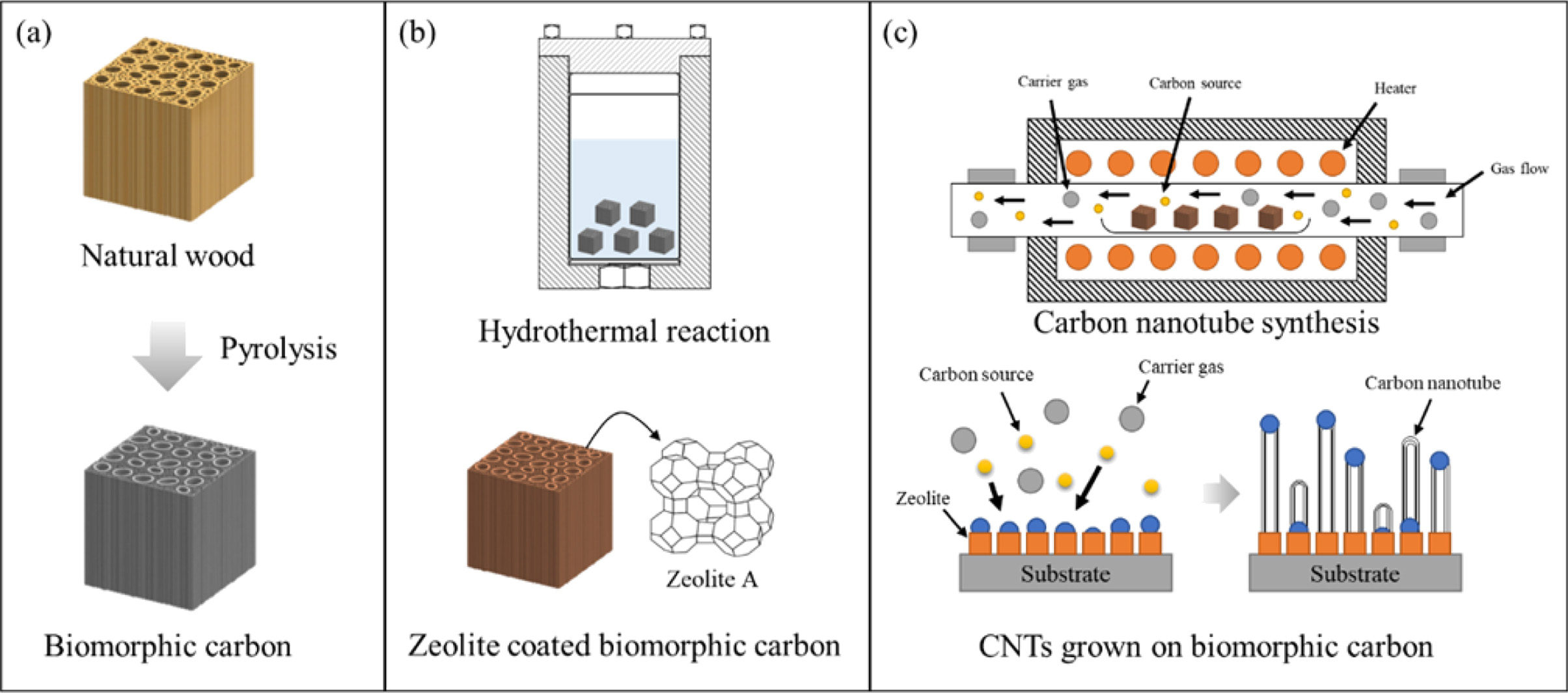
BCMs was prepared using Cypress (Hinoki) by the following steps. The samples (10 × 10 × 20 mm3) were then dried in an oven chamber at 120 oC for 24 hr. The BCMs were prepared by the pyrolysis of Cypress in the presence of Ar. During the carbonizing process, the samples were slowly heated up to 600 oC (0.5 oC/min) for 6-8 hr in an electric furnace with an N2 flow (10 sccm). The temperature was raised up to 1,000 oC (3 oC/min) under a vacuum atmosphere, and then cooled to room temperature to make BCMs, as shown in Fig. 1(a).
Template synthesis and coating on BCMs
Tetramethylammonium hydroxide (TMAOH, Sigma-Aldrich), Aluminum isopropoxide (AIP, Sigma-Aldrich), Tetraethyl orthosilicate (Si(OC2H5)4, Sigma-Aldrich), and Sodium hydroxide (NaOH, Sigma-Aldrich) were used as raw materials. To synthesis LTA on the BCMs [13], 20.8 g of AIP was dissolved in 280 g of distilled water using a magnetic stirrer, followed by stirring for 2 hours, and then 87.0 g of TMAOH was added. At the same time, 1.0 g of NaOH was dissolved in 80.0 g of distilled water in another beaker, 46.0 g of Si(OC2H5)4 was added dropwise, and the two solutions were mixed and stirred until clear. The final clear gel was transferred to an autoclave, and then template synthesis and coating on BCMs were carried out in the rector at 90 oC for 3 days, as shown in Fig. 1(b).
Catalyst loading and synthesis of CNTs on BCMs
Fig.1(c) shows the process of the synthesis of CNTs in an LTA-BCMs. To load the metal catalyst on BCM, Iron(II)-chloride tetrahydrate (FeCl2 · 4H2O) and Cobalt (II)-chloride hexahydrate (CoCl2 · 6H2O) were supplied by SANCHUN. Nickel chloride tetrahydrate (NiCl2 · 4H2O) and Copper (II) chloride dihydrate (CuCl2 · 2H2O) were obtained from Sigma-Aldrich. Each catalyst material of 0.1 g was dissolved in 40 mL of distilled water, placed in a 50-mL tube, loaded with LTA-coated BCMs, and mixed and loaded for 30 seconds using a Vortex mixer. After aging at room temperature for 1 hour, it was separated from the solution, dried in a 70 oC oven, and used as a sampler for CNTs syntheis. To synthesize CNTs, a catalytic decomposition of carbon source (C2H2, acetylene) on metal catalyst loaded LTA-BCMs was carried out in an electric furnace at 650 oC for 60 min with a nitrogen atmosphere (200 sccm).
Characterization
The morphology and the physicochemical chara- teristics of BCMs, LTA template and CNTs were inversitigated by field emission scanning electron microscopy (FESEM LEO 1530 VP, 1.0kV), high-resolution transmission electron microscopy (JEOL JEM-3011, 200kV), X-ray diffraction (Rigaku D/max 2500 VL/PC) using Cu Ká radiation, thermogravimetric analysis (TGA, Seiko Extar 7300) and Raman spec- troscopy (FRA-106/S, 1064 nm Nd-YAG).
|
Fig. 1 Schematic diagram for the synthesis of CNTs on BCMs; (a) pyrolysis, (b) template coating and catalyst loading, and (c) CNTs synthesis. |
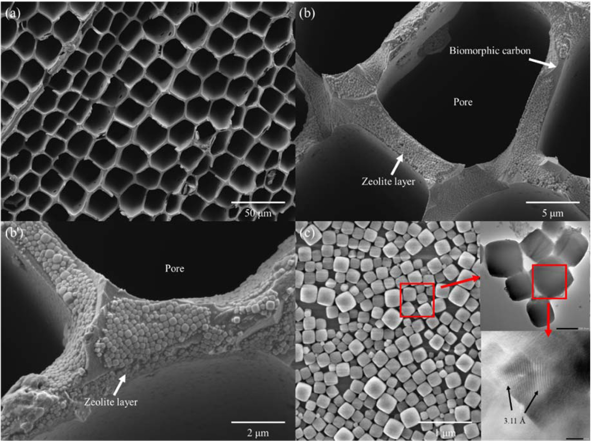
Figs. 2(a) show a hexagonal cell structure of BCMs, which has a pore size in the range 18.6 to 38.3 μm, and each cell-wall thickness is about 2.30 ~ 1.40 μm. Most of the cellular pores are rectangular, and the distribution shows a regular net with carbon walls joined to each other. The compressive strengths of Hinoki with a pore size of 19.60 μm, and a wall thickness of 2.3 μm are 52.65 MPa. The LTA template are uniformly coated inside and outside of the honeycomb structure as shown in Fig. 2(b) and (b'). A single phase of LTA template reflected in 2θ = 7o (200), 10o (220), 13o (222), 22o (531), and 24o (600) was found in the obtained XRD analysis with compared to JCPDS file # 97-002-4901. This is a well-developed cubic arrangement of eight tetrahedra with D4R [13]. All the FESEM and TEM (insert) shown in Fig. 2(c) reflect both a high crystallinity and uniform size distribution of LTA crystals.
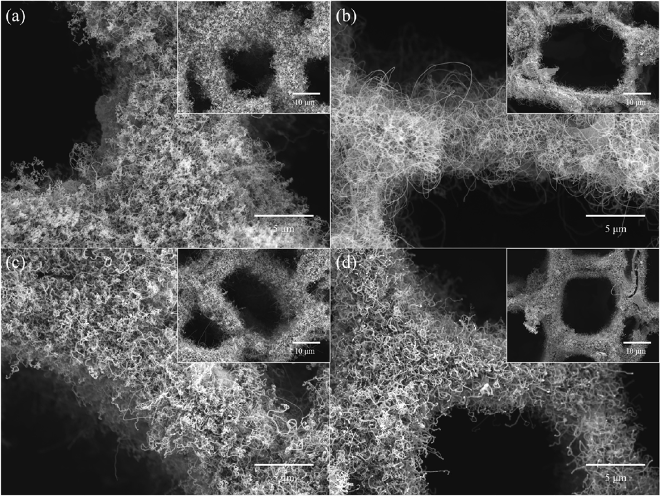
Fig. 3 shows FESEM images of CNTs grown on Fe-, Co-, Cu-, and Ni-loaded LTA-BCMs at 650 oC for 60 min. All CNTs were uniformly and tightly grown inside and around the pores of the BCMs. The synthesized CNTs were found to be more entangled and close networks overall LTA-coated BCMs (Fig. 3(b)). All CNTs show a bamboo-like structure and are typically MWCNTs. The yield of CNTs was very good in Co- and Fe- loaded BCMs as shown in Fig. 3(b) and (a), respectively.
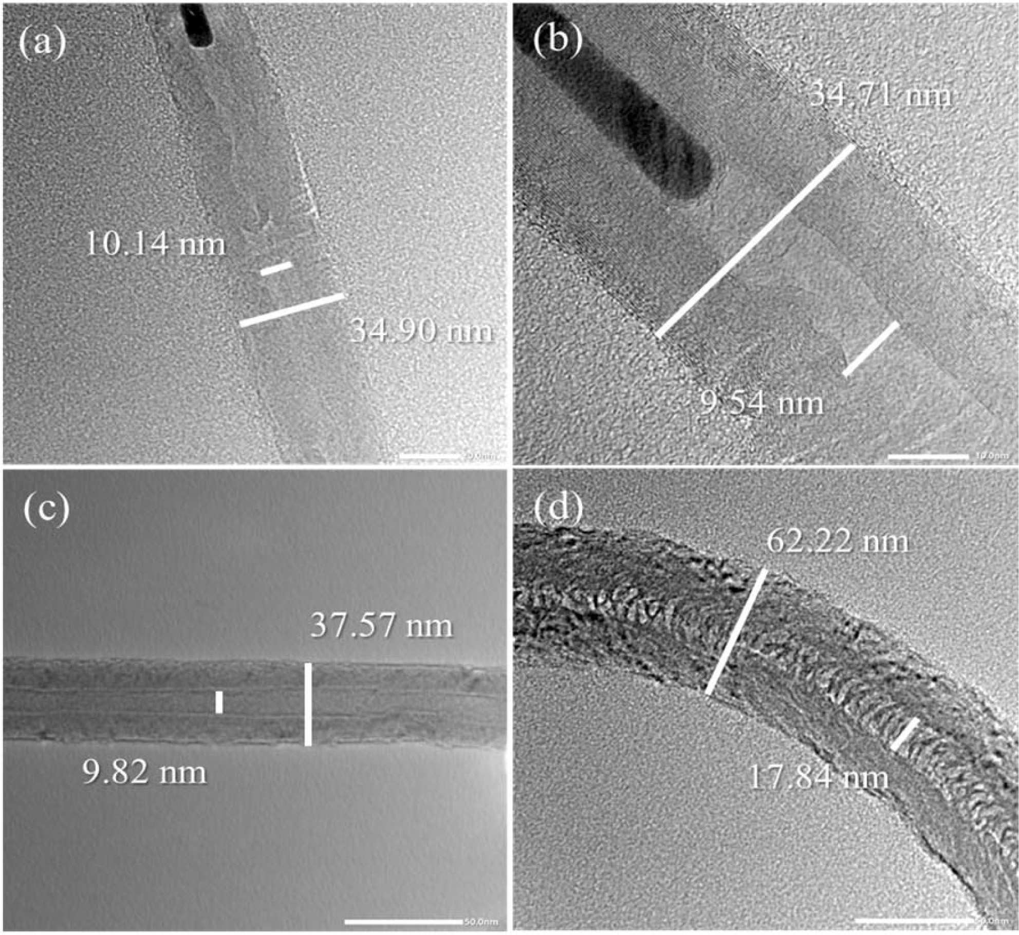
Fig. 4(a) shows the HRTEM images of multiwall CNTs (MWCNTs) that were grown on (a) Fe-, (b) Co-, (c) Cu-, and (d) Ni-LTA-BCMs at 650 oC for 60 and 120 min, respectivley. The CNTs in the TEM image of Fig. 4(a) show uniform outer walls with a diameter of approximately 34.90 nm and an inner diameter of 10.14 nm. The outer walls of CNTs in Fig. 4(b) are comparatively thicker, and a densely layered structure with diameters of 34.71 nm, was formed. Some isolated CNTs (Fig. 4(a), (b)) point to the so-called base-growth model, but some of them point to the tip-growth model of CNTs in our CCVD process [14, 15]. Due to changes in the shape and state of the catalyst nanoparticles during the growth, there is another possibility that they can be located anywhere within the CNTs [16, 17]. In addition to Ni-catalyst, some belt-like carbon materials were formed rather than CNTs, as shown in Fig. 4(d).
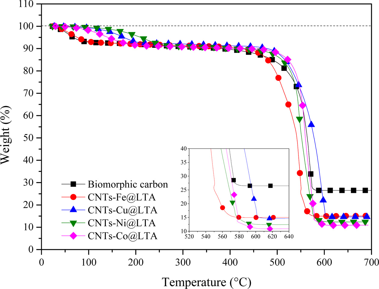
TGA curves of CNTs are shown in Fig. 5. All CNT samples represent an initial weight-loss (up to ca. 195 oC) tendency, which may involve the loss of physically adsorbed water on LTA template part of BCMs. The weight loss due to combustion of carbon begins at temperature of ≥ 400 oC depending on the carbon species [18]. All samples a two-step combustion process can be identified. The first stage (385 oC ~ 470 oC) corresponds to the combustion of the amorphous carbon species, and the second stage (480 oC ~ 618 oC) is the weight reduction due to the combustion of multi-wall carbon nanotubes with varying degree of graphiti- zation. The MWCNTs has combusted until ≥ 620 oC. After that, the samples keep a weight-loss pattern due to biomorphic carbon combustion. The main reason for the two-step pattern was that decomposition of C2H2 on metal catalysts leads to the formation of CNTs [19]. During the heat treatment process, the oxidation reaction of the metal catalyst nanoparticles did not occur, so that the weight gain was not observed. The carbon yield of CNTs synthesized by catalyst metal-containing CCVD is calculated as follows:

where mcat is initial catalyst amount (before reaction) and mtot is the total sample weight after synthesis [20]. From the TGA curves, the estimated amount of carbon yield has been allowed.
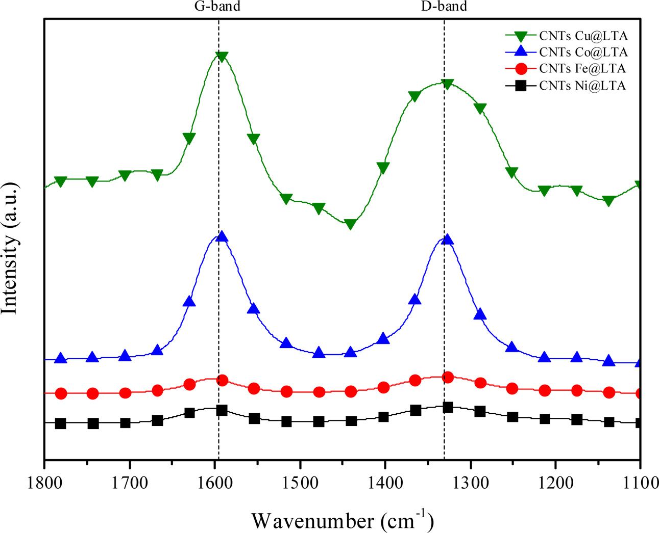
Fig. 6 shows the Raman spectra of the synthesized CNTs on BCMs. The spectrum of our CNTs has two band at around 1,340 cm−1 (D-band) and 1,600 cm−1, (G-band), respectively. These band correspond to the vibrations of carbon atoms with dangling bond in plane terminations of disordered sp2-hybridized carbon materials and symetric tangential stretching (E2g) mode of vibrations in 2D hexagonal lattice of highly oriented crystalline graphite [21].
The strength of the G-band to D-band ratio is used to evaluate defects and qualitative properties of CNTs. The ID/IG values in this work are between 0.97 and 1.18, which is consistent with literature for MWNTs grown by CVD (ID/IG = 0.7-1.3), which represent high-quality grown CNTs [22]. CNTs grown on Ni-and Cu-LTA-BCMs show higher value of ID/IG ratio of 1.17 and 1.18, indicating the presence of structural distortion and more amorphous carbon [23]
|
Fig. 2 FESEM images of (a) BCMs, (b) (b') LTA coated BCMs, and (c)FESEM and TEM (inset) image of LTA crystals. |
|
Fig. 3 FESEM images of CNTs grown on (a) Fe-, (b) Co-, (c) Cu-, and (d) Ni- loaded LTA-BCMs at 650°C for 60 min |
|
Fig. 4 HRTEM image of CNTs synthesis on (a) Fe-, (b) Co-, (c) Cu-, and (d) Ni-LTA coated BCMs at 650°C for 60 min. |
|
Fig. 5 TGA curves of CNTs synthesized on Fe-, Co-, Cu-, and NiLTA coated BCMs at 650 oC for 60 min. |
|
Fig. 6 Raman spectra of CNTs synthesized on Fe-, Co-, Cu-, and Ni-LTA coated BCM at 650°C for 60 min |
Multi-wall carbon nanotubes synthesized on metal ion loaded BCMs were achieved with both high quality and moderate carbon yield between 15.50 and 11.37%, because the uniform cubic structure of an LTA template can be coated homogeneously all over the BCMs surface. MWCNTs obtained at 650°C exhibited considerable an outer wall thickness of 34.71~37.57 nm and a narrow inner hole of 9.54~10.14 nm. The CNTs grown on Cu-loaded BCMs achieved the highest Raman ratio of ID/IG = 1.18, but in the carbon yield, it achieved a moderate result of 11.77%. The high carbon yield and morderate quality of CNTs were achieved from Co-loaded BCMs.
This research was supported by the Basic Science Research Program through the National Research Foundation of Korea (NRF), funded by the Ministry of Education (201800790001).
- 1. S. Iijima and T. Ichihashi, Nature 363[6430] (1993) 603-605.
-

- 2. C. Yu, L. Shi, Z. Yao, D. Li, and A. Majumdar, Nano Lett. 5[9] (2005) 1842-1846.
-
- 3. J.K. Holt, H.G. Park, Y. Wang, M. Stadermann, A.B. Artyukhin, C.P. Grigoropoulos, A. Noy, and O. Bakajin, Science 312[5776] (2006) 1034-1037.
-
- 4. J.G. Park, S.Y. Kim, I. S. Han, and I.J. Kim, J. Ceram. Proc. Res. 21[2] (2020) 170-191
-
- 5. A.S. Brady-Estévez, S. Kang, and M. Elimelech, Small 4[4] (2008) 481-484.
-
- 6. A. Stafiej and K. Pyrzynska, Sep. Purif. Technol. 58[1] (2007) 49-52.
-
- 7. Y.-H. Li, J. Ding, Z. Luan, Z. Di, Y. Zhu, C. Xu, D. Wu, and B. Wei, Carbon 41[14] (2003) 2787-2792.
-
- 8. G.D. Nessim, Nanoscale 2[8] (2010) 1306-1323.
-
- 9. A. Srivastava, O.N. Srivastava, S. Talapatra, R. Vajtai, and P.M. Ajayan, Nature Mater. 3[9] (2004) 610-614.
-
- 10. G. Zxhu, S. Qiu, J. Yu, Y. Sakamoto, F. Xiao, R. Xu, and O Terasaki, Chem. Mater. 10 (1998) 1483-1486
-
- 11. Y.R. Son, M.K. Kim, S.G. Ryu, and H.S. Kim, ACS Appl. Mater. Interfaces 10[47] (2018) 40651-40660.
-
- 12. S.J. Datta, C. Khumnoon, Z.H. Lee, W.K. Moon, S. Docao, T.H. Nguyen, I.C. Hwang, D. Moon, P. Oleynikov, O. Terasaki, and K.B. Yoon, Science 350[6258] (2015) 302-306.
-
- 13. J.G. Park, S.Y. Kim, Z. Wei, J.H. Jeon, S.Y. Kim, and I.J. Kim, J. Ceram. Proc. Res. 18[2] (2017) 161-165.
- 14. J. Ramírez-Rico, J. Martínez-Fernandez, and M. Singh, Intl. Mater. Rev. 62[8] (2017) 465-485.
-
- 15. M. Kumar and Y. Ando, in “Carbon Nanotube Synthesis and Growth Mechanism” (IntechOpen Limited, 2010) p. 7.
-
- 16. M.J. Height, J.B. Howard, J.W. Tester, and J.B. Vander Sande, J. Phys. Chem. B 109[25] (2005) 12337-12346.
-
- 17. M.H. Kuang, Z.L. Wang, X.D. Bai, J.D. Guo, and E.G. Wang, Appl. Phys. Lett. 76[10] (2000) 1255-1257.
-
- 18. S. Mazumder, N. Sarkar, J.G. Park, I.S. Han, and I.J. Kim, Mat. Chem. Phys. 171[(2016) 247-251.
-
- 19. W. Zhao, H.S. Kim, H.T. Kim, J. Gong, and I.J. Kim, J. Ceram. Proc. Res. 12[4] (2011) 392-397.
- 20. Y. Liu, H. Ba, D.-L. Nguyen, O. Ersen, T. Romero, S. Zafeiratos, D. Begin, I. Janowska, and C. Pham-Huu, J. Mater. Chem. A 1[33] (2013) 9508-9516.
-
- 21. G. Krishnamurthy and S. Agarwal, Bull. Korean. Chem. Soc. 34[10] (2013) 3046-3054.
-
- 22. K. Kwok and W.K.S. Chiu, Carbon 43[2] (2005) 437-446.
-
- 23. S. Chandrakishore and A. Pandurangan, Chem. Eng. J. 222 (2013) 472-477.
-
 This Article
-
2021; 22(3): 301-305
Published on Jun 30, 2021
- 10.36410/jcpr.2021.22.3.301
- Received on Aug 20, 2020
- Revised on Jan 15, 2021
- Accepted on Feb 5, 2021
Services
- Abstract
introduction
experimental setup
results and discussion
conclusions
- Acknowledgements
- References
- Full Text PDF
Shared
Correspondence to
- Ik Jin Kim
-
Korea Institute of Energy Research(KIER), #152, Gajeong-gu, Daejeon 34129, Korea
Tel : +82-41-660-1661 Fax: +82-41-660-1661 - E-mail: ijkim@hanseo.ac.kr
Clean-Energy Research Institute(CRI), Hanyang University, 222, Wangsimni-ro, Seongdong-gu, Seoul, 04763, Korea
E-mail: jcpr@hanyang.ac.kr