


- Kinematic behavior of melted glass for hot-extrusion
Y.T. Huanga, W.C.J. Weia,* and A.B. Wangb
aDept. Mat. Sci. Eng., National Taiwan University, 106, Taiwan
bInstitute of Applied Mechanics, National Taiwan University, 106This article is an open access article distributed under the terms of the Creative Commons Attribution Non-Commercial License (http://creativecommons.org/licenses/by-nc/4.0) which permits unrestricted non-commercial use, distribution, and reproduction in any medium, provided the original work is properly cited.
This study uses fused-deposition modeling (FDM) to produce thin melted glass for 3D printing at 1,300 oC. A melt-extrusion module by the authors [Wei, 2014, 2016] has been used to produce 3D structure of alumina/polymer mixtures and Cu-Zn key parts. In this work, we determined the extrusion characteristics of various feedstocks (one borosilicate glass and simulating fluids) and to determine the kinematic behavior of the fluids. PVB-solvent mixtures were synthesized for simulating the viscous characteristics of melted glasses and extruded through ceramic nozzles of 0.1~0.4 mm diameter at room temperature to simulate an oxide glass that was extruded at 1,000 - 1,300 oC. The air-pressure, the die-diameter, the extrusion rate, the viscosity of the melts and the friction between the wall and the container was calibrated and measurement. Five major forces acting on the module were discussed in order to reveal the extrusion behavior of continuous glass fiber
Keywords: Melt extrusion, Simulation, Glass, Additive manufacturing, 3DP
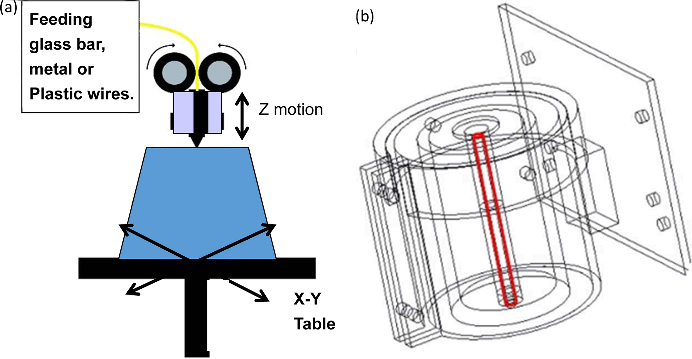
Fused Deposition Modeling (FDM) using rod-shape feeding materials is one of facile methods for additive manufacturing [2] to produce 3-dimensional (3D) parts with reasonable complexity. There are two major issues for the efficient production of complex parts using FDM [3]: cost-effective wire is offered for the FDM, and using easy-operated melt extrusion (ME) module. The detailed design of the process is shown in Fig. 1(a).
One hot-extrusion device combined with heating elements was patented in a previous work by the author [1]. The ME module consisted of a wire feeder, a SiC-FeSix heating element, a high purity Al2O3 (AlO) or stainless steel (SS) tube with a small hole at the lower end (called a nozzle), a thermal insulation layer and an Al-alloy housing. A diagram of the module is shown in Fig. 1(b). A wire (e.g. glass rod) feeding into the top of the nozzle is melted in the tube and flows through the nozzle. When the melted fluid has sufficient downward driving force, a viscous fluid of molten glass, a mixture of Al2O3/plastics [4] or melted Cu-Zn alloys [5] has been extruded out from the nozzle. The ME module is potentially operated at temperatures as high as 1,300 oC.
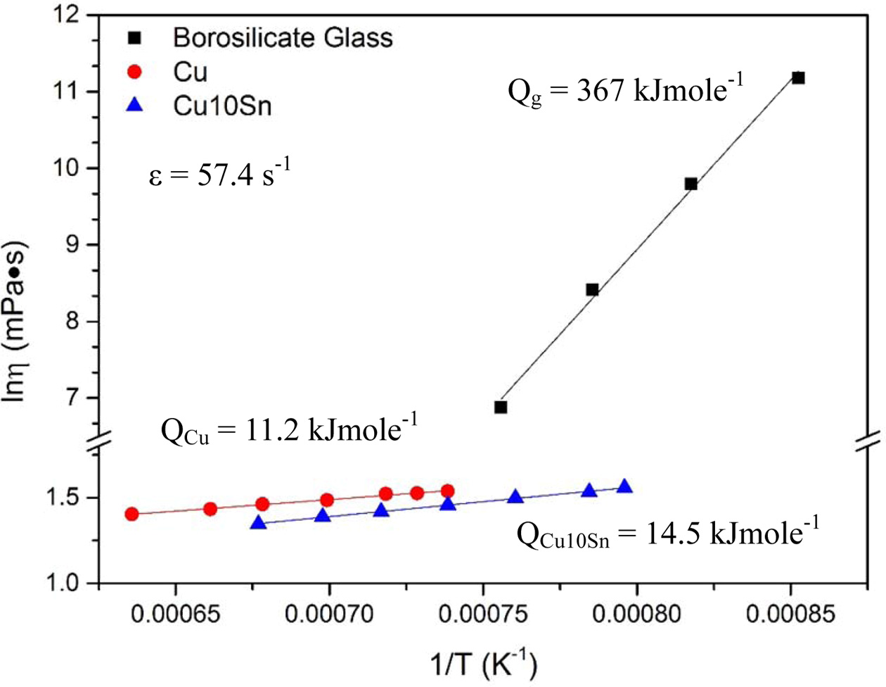
Glass becomes viscous when it is melted at temperatures slightly high than its meting temperature [6-9]. It was demonstrated flowing out from the nozzle at a very slowly rate [6], and reported behaved pseudo-plastically. Previous studies by the authors reported the viscosity and activation energy of one melted glass and Cu-Zn alloys [5, 7] (Fig. 2). The viscosity of a typical boron-silicate glass, 32Na2O-34SiO2-5B2O3-29TiO2 (called TN05) ranges from 1,000 mPas to 100,000 mPas between 900-1,100 oC. This glass can be slowly extruded through a 0.4 mm nozzle at a very low rate at 1,200 oC [7]. It was not practical to manufacture 3D parts if the extrusion rate was slower than 20 s-1.
Pure plastics, such as Acrylonitrile Butadiene Styrene (ABS), have been fused and deposited at ca. 200 oC. Several factors determine the performance of the extruded material: the melting temperature and the viscosity of the melted material, the dimensions of the nozzle and the friction between the fluid and the surface of the tube.
The flow characteristics of the extruded material at high temperature are important for successful melt-extrusion. However, no studies are reported on the kinematic behavior of melted glasses during 3D HE. This study synthesizes two series of fluids to simulate melted glass/metal alloys: ethanol and 1-pentanol with polyvinyl butanol (PVB). The changes in the pressure and velocity in the ME module are measured and the kinematic properties of hot melted fluid extrusion are determined.
|
Fig. 1 Schematic diagrams of (a) a typical FDM setup consisted of feeder and feeding wire, a hot nozzle, 3D control platform. (b) A melt extrusion (ME) device, which includes a heating element combined with Si-based heating elements and Fe-Cr-Al wires, a ceramic tube as nozzle, and a refractory support as thermal insulation layers [5]. |
|
Fig. 2 Arrhenius plot of three materials tested by viscosity and 1/ T. Activation energy and shear rate of the tests are calculated by the best fitted lines. The data of borosilicate glass and Cu-based alloy are from our previous work [5, 10], respectively. |
The extrusion behavior of a fluid can be simplified when the Reynolds number (Re) is less than 2100 [8]. A laminar flow with either Newtonian or pseudo-plastic behavior is considered in this study. The simulation of the fluid behavior of molten materials involves some preliminary steps and some assumptions.
(1) Solutions with a viscosity similar to that of typical glass are prepared. The glass - TN05 - is selected as the example of viscosity. This is a highly viscous fluid that melts at 1 000-1 200 oC;
(2) The range of the shear rates is determined from the printing speed of commercial 3D printers. FDM printers are currently operated at a flow rate of 20-250 mms-1. The shear rate (g) for a flow in tube is calculated using the average flow rate (V) as g = V / 4r. Therefore, the range of the shear rate used to test the ME module is 25-313 s-1.
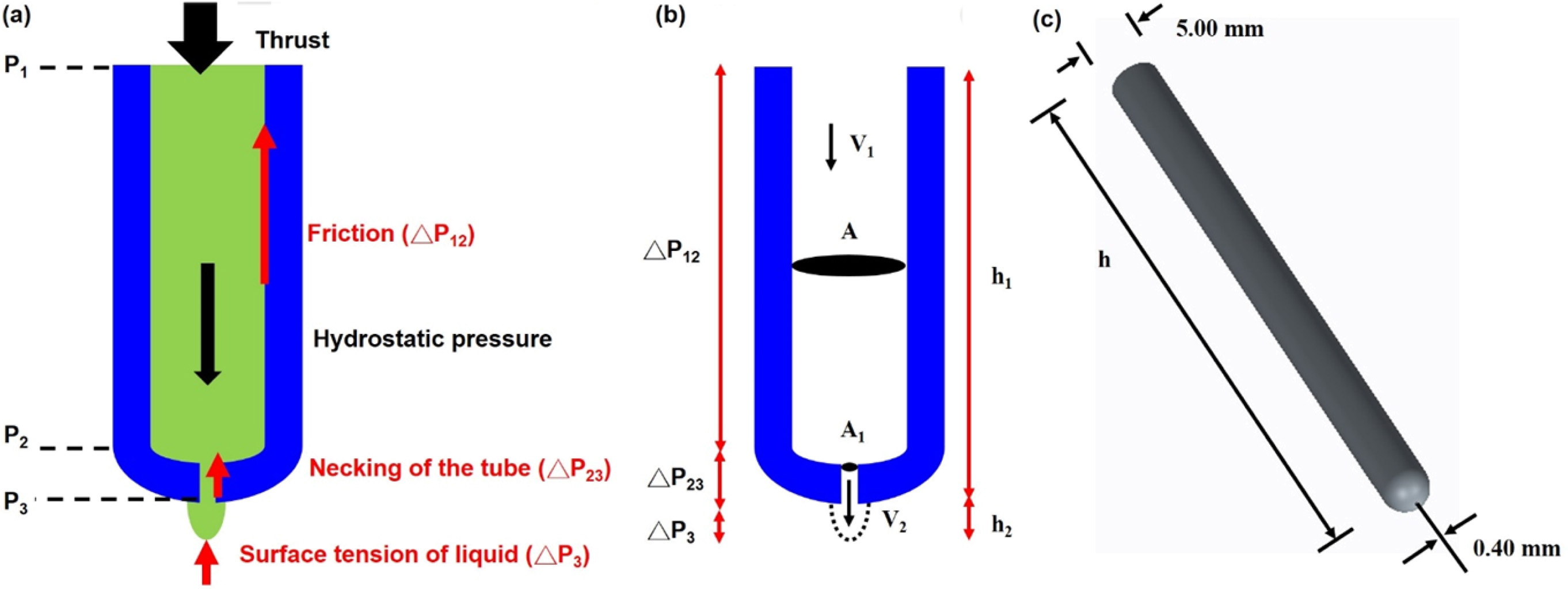
Five forces acting on a fluid are noted when a fluid is extruded through a tube with one small nozzle. Fig. 3(a) shows that the thrust (P1) and hydrostatic pressure (PH) are the two downward driving forces. In the opposite direction, friction with the wall (f), reduction of the cross section due to necking (A0/A1) in the tube and surface tension (P3) of a liquid drop are the three upward forces. When the net force is downward, the fluid flows continuously out of the nozzle. The decrease in pressure (ΔPij), the cross sectional area of the tube and nozzle, and the velocity of the fluid at different positions are defined in Fig. 3(b).
Pressure drop due to wall friction
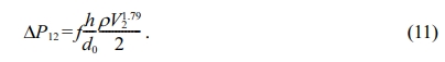
The flow rate for a viscous fluid in a tube is reduced by friction between the fluid and the surface of the wall. The decrease in pressure (ΔP12) between positions 1 and 2 is:
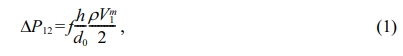
where h and d0 are the length and diameter of the barrel (inner dimensions of the tube), ρ is the density of the fluid, and f is a combined coefficient of friction. For a laminar flow, this combined coefficient of friction is given by [8]:
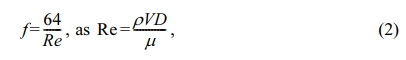
where μ is the viscosity of the fluid and D is inner diameter of the tube (=2r). Eqs. (1) and (2) are combined to give:
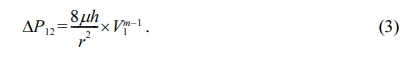
For a Newtonian fluid, the exponent of the velocity term (V1) is equal to 1.0; i.e. m - 1 = 1 [8, 9]. The exponent value changes if the fluid is not Newtonian.
Pressure drop due to necking
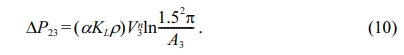
An additional decrease in pressure occurs if the cross section of the tube is reduced, as shown between positions 2 and 3 in Fig. 3(a). This decrease in pressure is described as below [9].
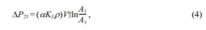
where KL is the geometric coefficient of the neck and (αKLρ) is a combined coefficient. V1 and V3 are related as V3 = V1(A1/A3), where A1 is the cross sectional area of the tube and A3 is the area of the nozzle with a diameter of 0.1~0.4 mm.
Decrease in pressure due to surface tension
If a drop of fluid forms at the tip of the extrusion, the decrease in pressure due to the surface tension (σ, in a unit of Ncm-1) acts against the initial stage of the extrusion and the pressure drop is given as below.
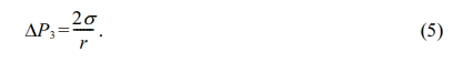
However, this factor can be ignored when the extrusion of the fluid is continuous.
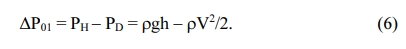
Driving force for the extrusion
Two forces are active when a fluid is extruded from a tube: gas thrust (PT) and hydrostatic pressure (PH). The thrust is given by the gas pressure in a pressure tank and results in a loss of dynamic pressure (PD=rV2/2) for a fluid that flows at velocity V1. If a force is used to push fluid through the tube, the decrease ΔP01 due to gravity and the flow of the glass melt is shown as below.
|
Fig. 3 Schematic drawing of an extrusion tube with a nozzle. (a) Positions and reverse forces, (b) the pressure drop causing by the friction of wall, necking of the tube, and the surface tension of the liquid, (c) the outer diameter and nozzle size of a 99.5% pure Al2O3 ceramic tube used in this study. |
Preparation of standard fluids
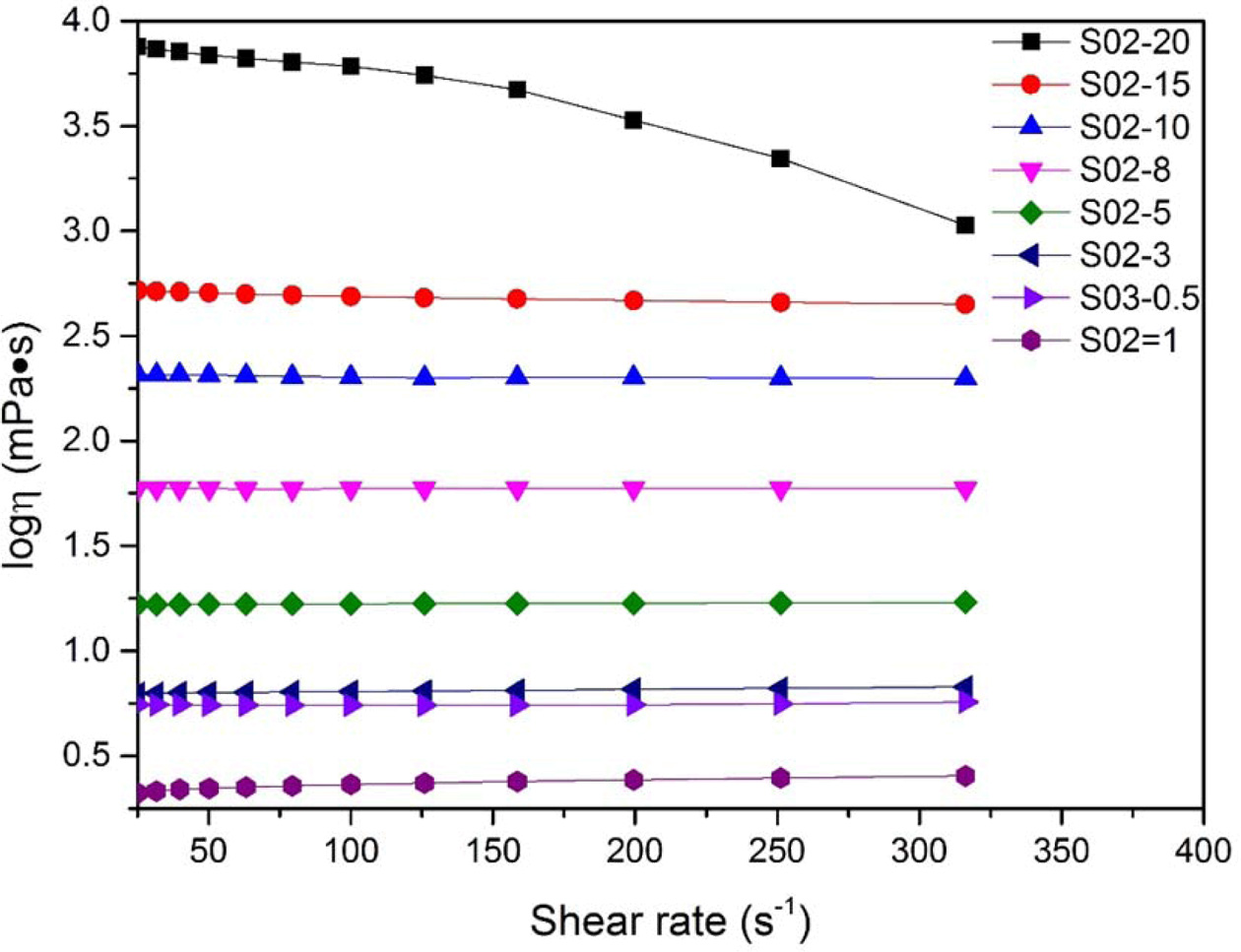
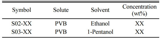
Two series of simulation fluids are used at room temperature. Their compositions are shown in Table 1. The number xx in suffix means that xx wt% PVB (polyvinyl butyral) is dissolved in ethanol solution. The viscosity of the ethanol (S02) and the 1-pentanol (S03) containing various PVB contents are plotted against shear rate in Fig. 4. For this range of viscosity, S02-20 solution is pseudo-plastic and behaves similarly to that of the molten glass (Fig. 2). S03-0.5 solution is nearly Newtonian and is used to simulate the behavior of a low-viscosity fluid (called a “thin fluid” in this study).
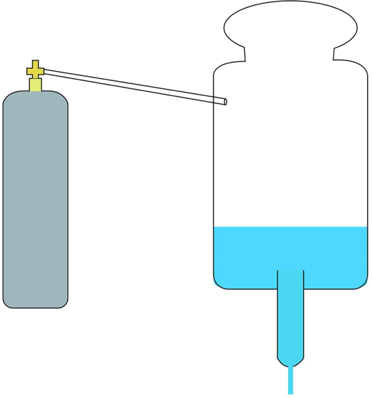
Calibration of thrust
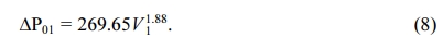
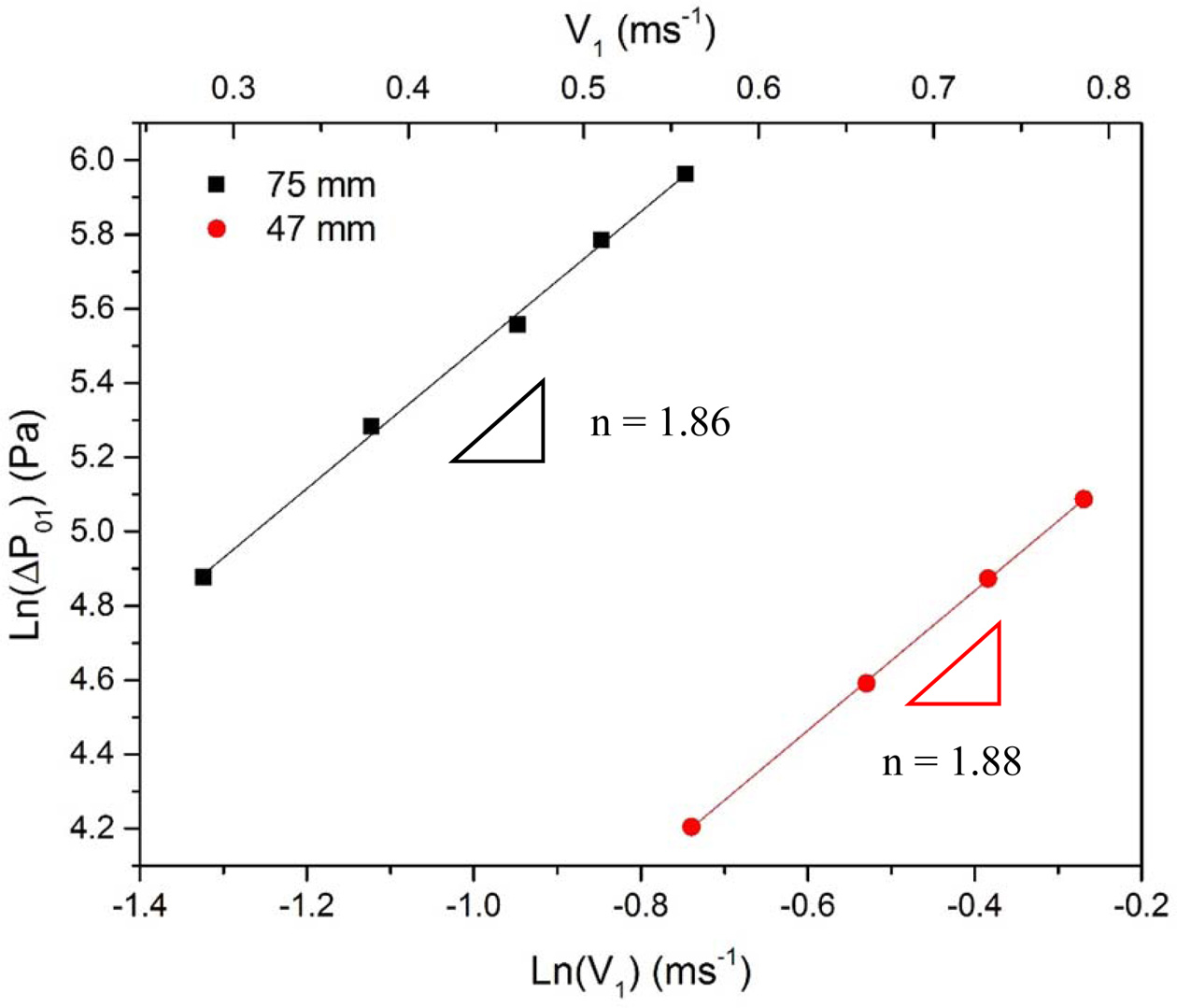
In order to maintain a constant hydraulic pressure (a water head, h), the decrease in pressure (ΔP01) of water supply was measured. A 3 mm hole was drilled in the bottom of two plastic bottles with diameter of 75.0 and 47.0 mm respectively, as shown in Fig. 5. Water flows through the neck of each bottle at a different pressures and the decrease in pressure and flow rate (V1) of the solution were measured and used to calculate ΔP01 (as shown in Appendix Table A1) using the equation as below.
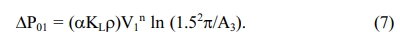
Taking the log of both sides, a fitting line for the data is shown in Fig. 6. The respective gradients (n) for the 75 and 47 mm-diameter bottles are 1.82 and 1.88, and the respective intercepts for the data are 2.84 and 2.43. The constant (αKL) for the 47 mm-diameter bottle is 0.060, and for the 75 mm-bottle is 0.131. The gas thrust is then calculated as below.
Testing procedures
Viscosity measurement
A co-axial viscosity meter (B-one, Lamy Rheology Ins., France) was used to measure the viscosity of the simulation fluids, TN05 glass and the Cu-Zn alloys, at various temperatures. Both fluids behave as a Newtonian fluid at low viscosity, but exhibit pseudo-plastic behavior when the viscosity exceeds 1,000 mPas. Therefore, S03-0.5 with a viscosity around 5.5 mPas is used as a thin solution, and S02-20 is used as a viscous fluid to simulate melted glass.
Surface morphology
SEM (JSM6510, JEOL, Japan) was used to observe the inner surface of various tubes (Al2O3, silica glass and SS tubes). The roughness of the surfaces was measured using AFM (Multimode 8, Bruker AXS Pte, Singapore)
|
Fig. 4 Viscosity of ethanol (S02) and 1-pentanol (S03) solutions containing PVB (xx wt%) plotted against shear rate. |
|
Fig. 5 Schematic diagram of the experimental connection of liquid container for supplying addition air/liquid thrust. The bottom of the container (pressure tank) connects with a flowing nozzle. |
|
Fig. 6 Normalized pressure loss (ΔP01) of S03-0.5 thin solutions flowing through pressuring container (Fig. 5) plotted against the flowing velocity. The slope of the fitting lines is 1.87+0.01. |
Friction in various tubes
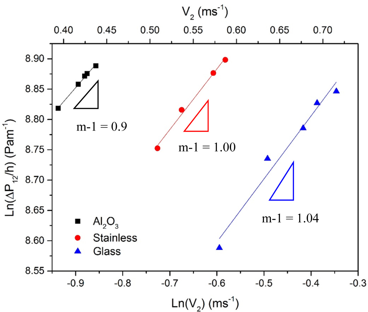
Three types of tubes (alumina, glass and SS tubes) have been used for the extrusion of various extruded materials, such as ABS or melted glass from 200 oC – 1,300 oC. Tubes of various lengths (23 mm - 250 mm) were used to calculate the decrease in pressure per unit length of the tube (ΔP12/h). (The calculations are shown in Appendix Table A2.) The kinematic relationship can be shown as below.
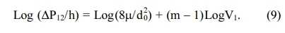
The respective gradients (m-1) for the three tubes (alumina, glass and SS tubes) are fitted (Fig. 7) to be either 0.90, 1.04, or 1.0. Therefore, the exponent for the velocity term in the following calculation is considered setting at 1.0, which is consistent with our preliminary understanding, 1.0 for the Newtonian fluid of S03-0.5. The respective intercepts for the gradients are 9.66, 9.22 and 9.38, respectively. This gives a constant in the second term in Eq. (9) of 25.9 for an alumina tube, 16.4 for a glass tube and 19.2 for a SS tube. The differences are mainly due to the differences in the surface roughness of the tubes.
The calculation for the combined coefficient of friction (f) for each tube is (as shown in Table A2) using Eq. (2). It is seen that a glass tube has the lowest values (0.10 – 0.13) for the coefficient. When the viscosity, the density of the fluid, and the diameter of the tube are constant, the coefficient f is a function of the flow velocity. The faster the flow, the smaller is the coefficient. Therefore, the f value for the same tube can differ slightly.
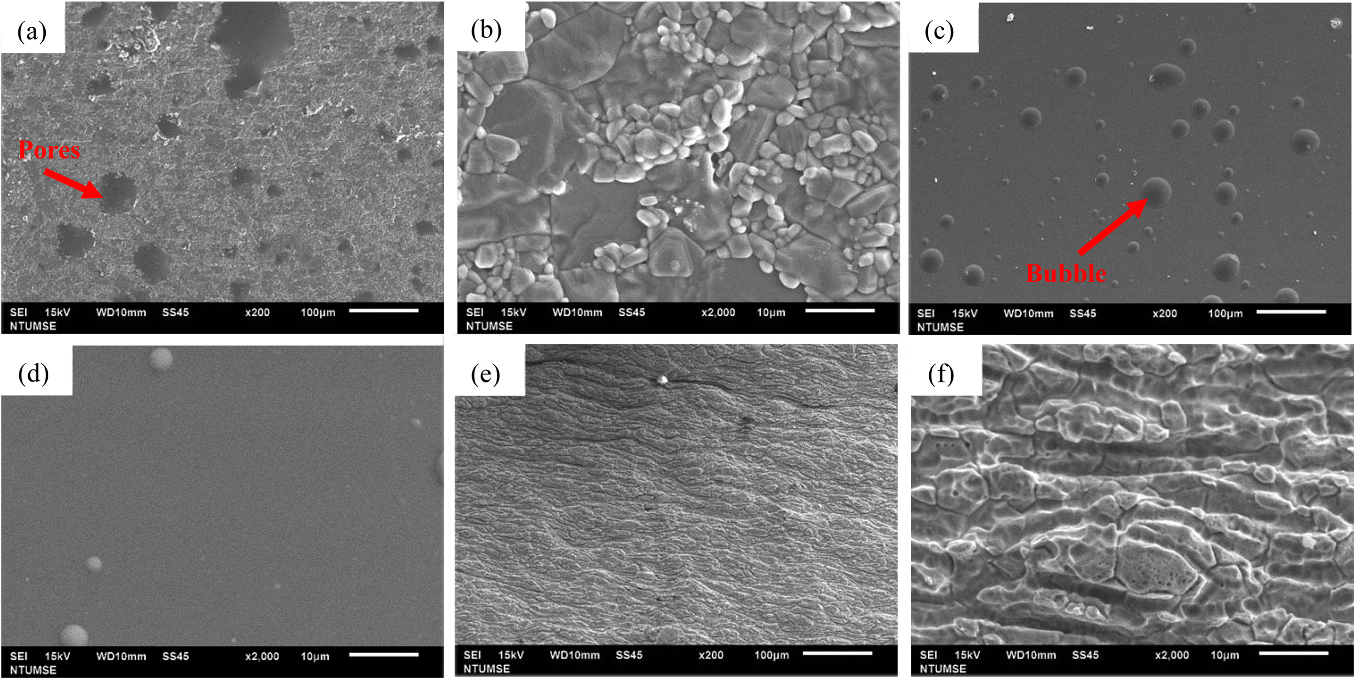
The Al2O3 tube has the largest combined coefficient of friction (Table 2). The microstructure (Figs. 8(a) and 8(b)) of the inner surface of the Al2O3 tube consists of large and micron-size grains, which give a Rz value close to 0.92 mm. The Rz value for the SS tube is 2.16 mm (Table 2), which indicates a rough surface, evidence from the SEM micrographs (Figs. 8(e) and 8(f)) of the SS tube showing an anisotropic extruded texture. The roughness along the length of the tube is smaller than that at the cross section. The Rq (0.62) and Ra (0.39) values for the SS tube are the largest values among the three tubes.
Flow behavior for a Newtonian (thin) fluid
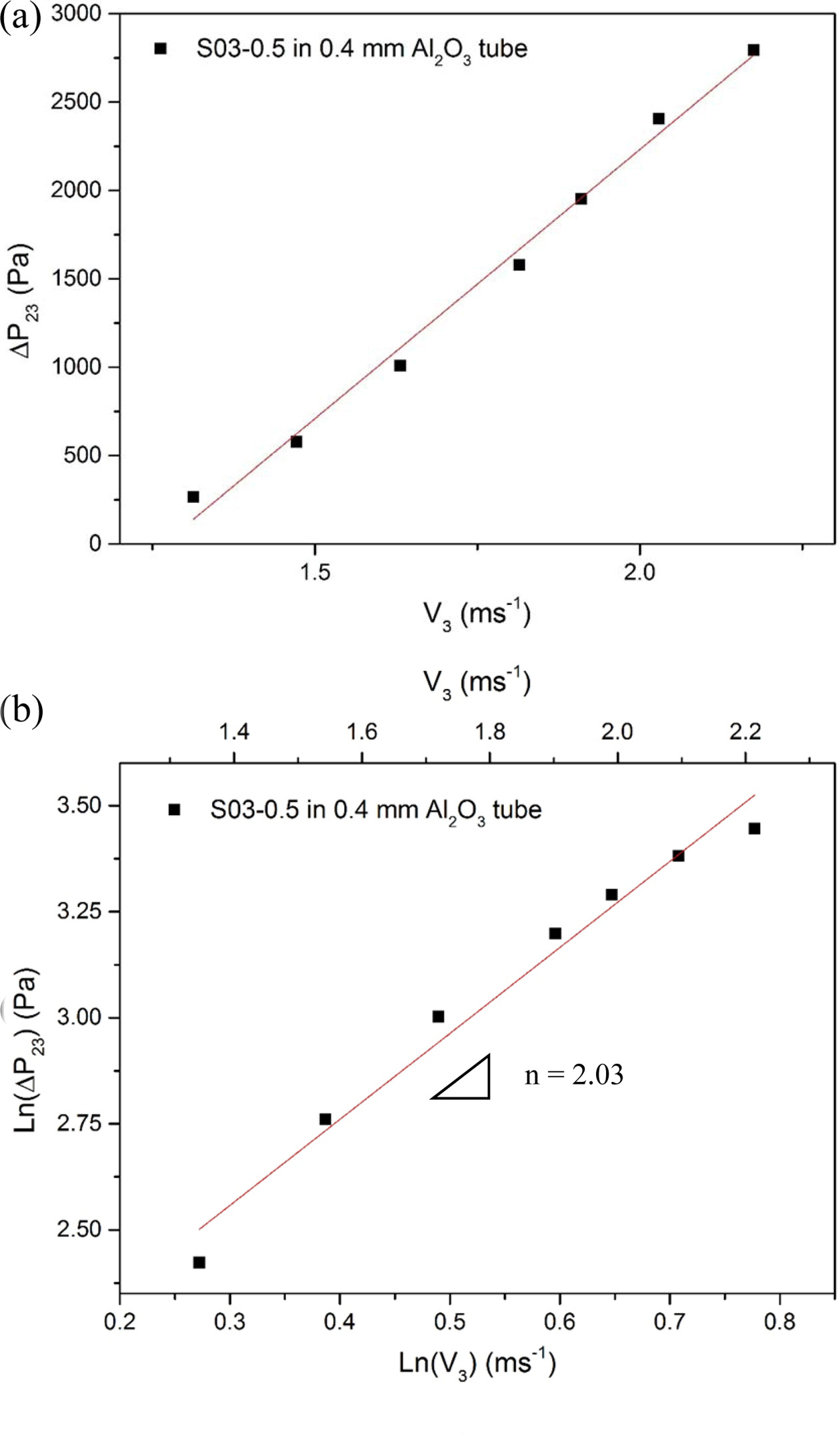
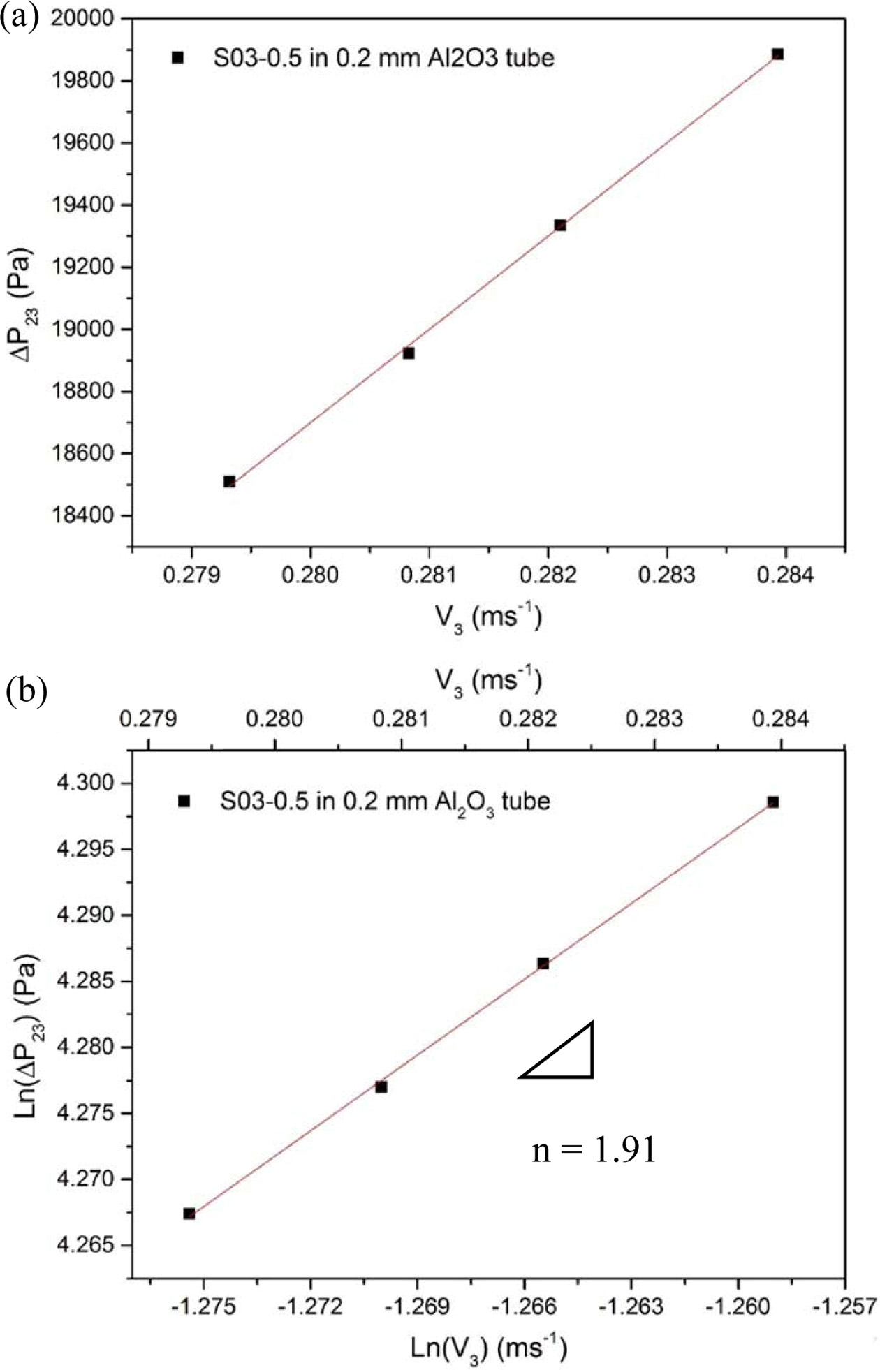
The flow for the thin solution S03-0.5 through Al2O3 tubes with a hole of 0.4 mm or 0.2 mm was measured to calculate the decrease in pressure in the tube. Various flow conditions were used to achieve ΔP23 (=PT+PH-P0-P01-P12) values (The calculation details are shown in Table A3). Figs. 9 and 10 show ΔP23 as a function of V3. Figs. 9(b) and 10(b) show the Ln-Ln plots which are used to calculate the exponent values (n) for the velocity V3 in the nozzle.
The n values are 2.03 and 1.91 and the intercepts are 1.95 and 6.71, respectively. Therefore, the constant αρKL is 1.74 for a fluid flowing through a 0.4 mm-diameter nozzle. The constant αρKL is 151 for a 0.2 mm-diameter nozzle. For a density 817 kgm-3 of S03-0.5, the β (= αKL) value is 0.002 for a 0.4 mm nozzle and 0.18 for a 0.2 mm Al2O3 nozzle.
Flow behavior for a viscous fluid
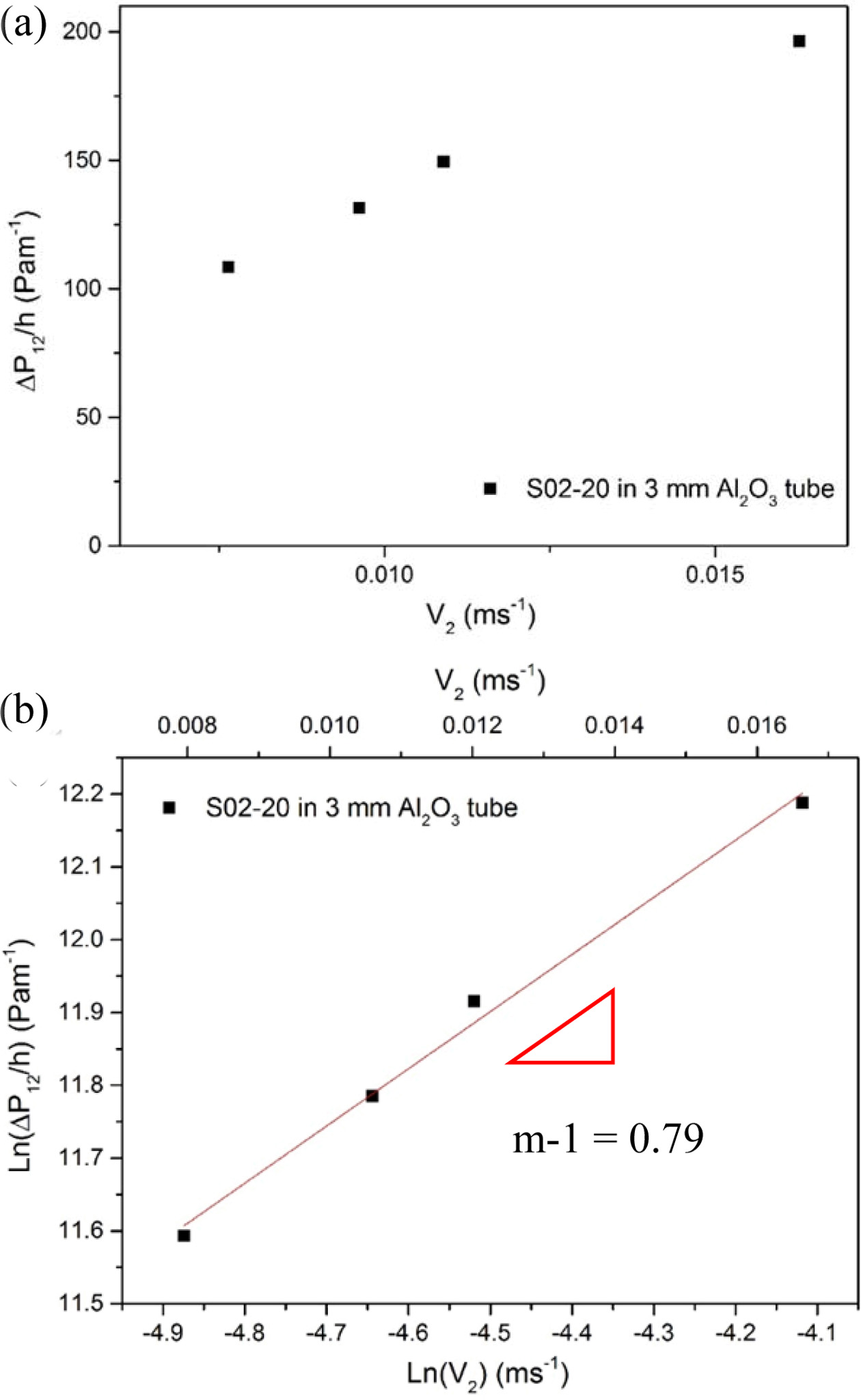
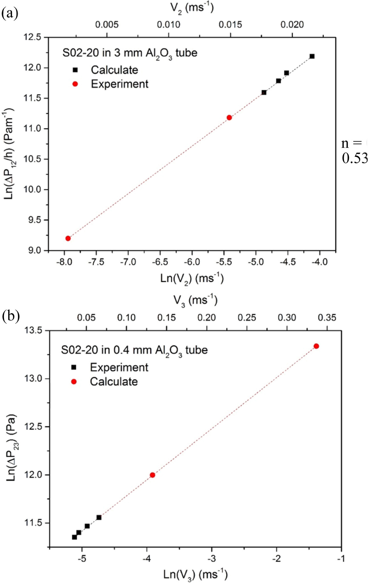
Highly viscous S02-20 fluid does not flow readily. (Table A4 in appendix shows the calculated results of the kinematic properties (ΔP12/h) of the viscous fluid, S02-20, flowing through an Al2O3 tube of 3.0 mm diameter.) This requires an extrusion thrust (P1) of 109 kPa to create a continuous flow. The variation is shown as the gradient of the fitting line in Fig. 11, which gives a velocity exponent (m-1) = 0.79. However, the exponent for the Newtonian fluid, i.e. S03-0.5, is 1.0. The decrease in pressure between positions 1 and 2 is given as below.
The results for the S02-20 fluid flowing through an alumina tube with a 0.4 mm nozzle have been calculated (as shown in Table A5). The flow velocity (V2) is very slow, at 6 - 10 mm·s-1 when it is driven by a 2.0 atm gas at PT. Therefore, additional force (PT) is needed at position 1 to extrude this highly viscous fluid.
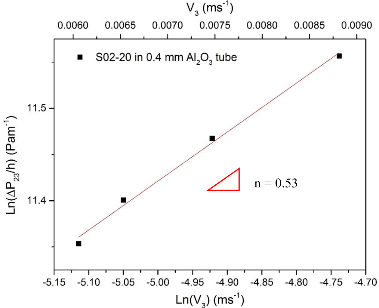
The relationship between ΔP23/h and the extrusion velocity V3 is shown in Fig. 12. The exponent n is 0.53 for the extrusion of this viscous fluid. This is significantly less than the value for a thin fluid flowing through the same nozzles because the friction acts on the fluid and varies with the velocity (V2).
The requirement of a thrust also means that the feed system for the filament can supply this pushing force to allow continuous extrusion. The results for the decreases in pressure, ΔP12 or ΔP23, clearly show due to a necking is about 300 times greater than that due to friction with the wall. Therefore, DP23 is the principal cause of the resistance for the extrusion of a fluid.
Thrust for the extrusion of a viscous fluid
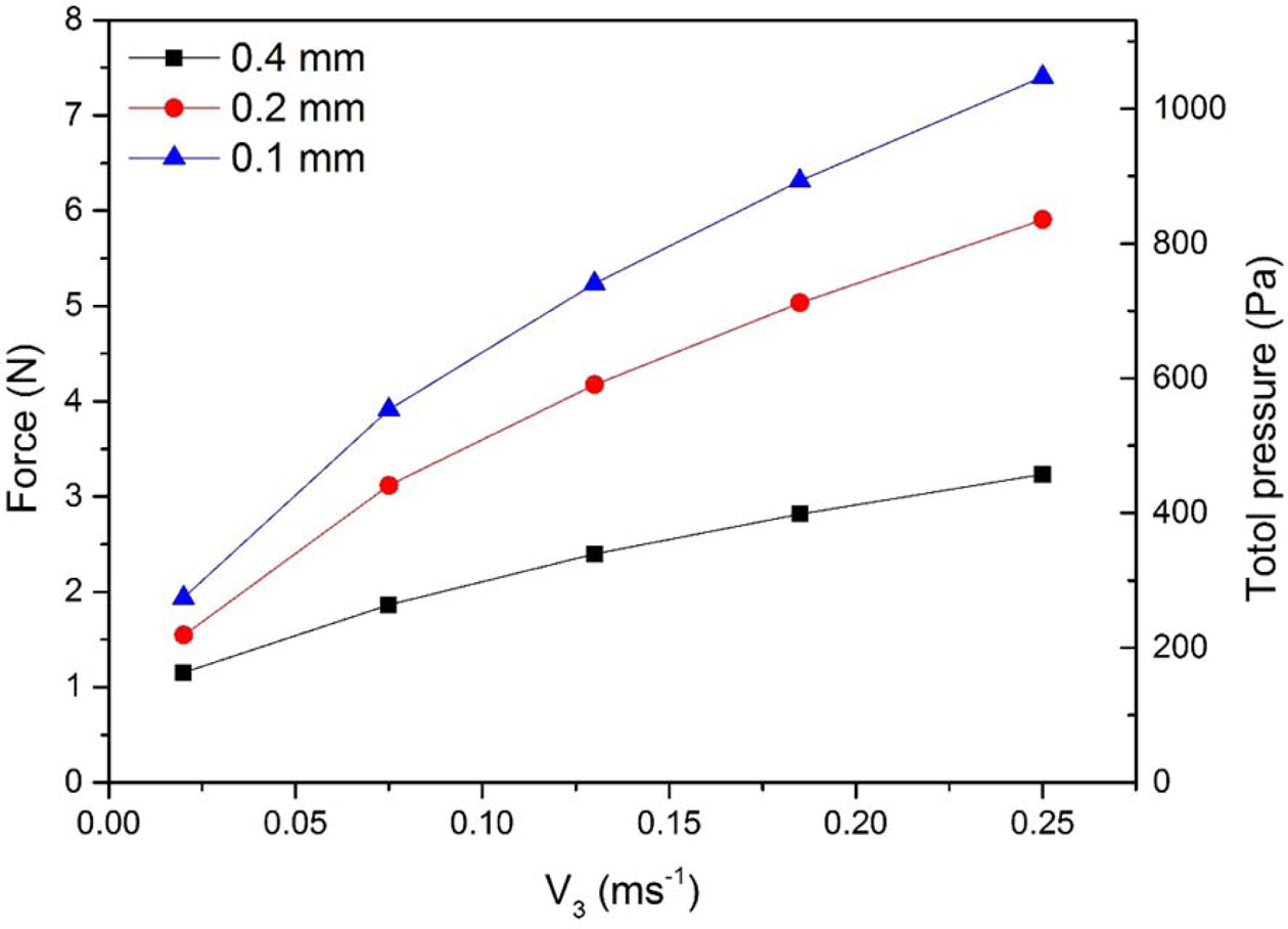
Previous data show that a thrust of almost 205 kPa (about 2 atm) is required to extrude a viscous fluid through a 0.4 mm nozzle at a slow rate (V2) of 0.88 cm.s-1. Therefore, an additional force 1.3 N - 1.5 N is required to extrude melted glass at high temperature, which can be seen in the video in the reference [3]. The simulation data have been used to determine how much thrust is required if performing a flow rate of 20 mms-1 to 250 mms-1 for a fluid with a pseudo-plastic viscosity of 1,000 ~ 7,000 mPa flowing through a smaller nozzle, e.g. 0.1 mm.
It is assumed that the decreases in pressure, DP12 and DP23 for the Al2O3 tube are similar to those for the previous tests. A flow rate V2 of 0.36 mms-1 to 4.44 mms-1 gives V3 of 20 to 250 mms-1 and a dependence of (m-1) = 0.79. The results are shown in Fig. 13(a). A similar method is used for V3 in Fig. 13(b) when n = 0.53, which is similar to the extrusion range for most commercial FDM machines. When the value of β (= αKLr) in Eq. (10) is a constant, the thrust that is required to extrude a fluid flowing through 0.4, 0.2 and 0.1 mm nozzles is calculated. (as shown in the Appendix in Table A6)
The thrust is small if the viscosity is high (7,000 mPa) and the flow rate (V3) is close to 20 mm*s-1. For the flow at a greater velocity, the viscosity decreases and more thrust is required, as shown in Fig. 14. Therefore, a viscous fluid, such as S02-20 or melted glass (TN05), flowing through a tube with a 0.4 mm nozzle at a normal speed requires a thrust of 1.1 N - 3.3 N. If the nozzle is 0.2 mm in diameter, a thrust of 1.5 N - 5.9 N is required for extrusion of melted glass. For a 0.1 mm-diameter nozzle, the wire feeder must supply a force of 1.9 N - 7.4 N.
|
Fig. 7 Normalized pressure loss per length of tube (ΔP12/h) of S03-0.5 thin solution flowing through three different tubes made of glass, stainless steel or Al2O3 plotted against the flowing velocity (V2). |
|
Fig. 8 SEM images of the inner wall surface of (a) and (b) Al2O3, (c) and (d) glass, (e) and (f) stainless steel tubes. |
|
Fig. 9 Normalized pressure loss (ΔP23) of S03-0.5 thin solutions flowing through a 0.4 mm-nozzle Al2O3 tube with a (a) in normal scale, (b) in nature logarithm scale, plotted against flowing velocity. |
|
Fig. 10 Normalized pressure loss (ΔP23) of S03-0.5 solutions flowing through a 0.2 mm-nozzle Al2O3 tube (a) in normal scale, (b) in nature logarithm scale, plotted against the flowing velocity. |
|
Fig. 11 Normalized pressure loss per length of tube (ΔP12/h) (a) in normal scale, (b) in nature logarithm scale, plotted against flowing velocity of S02-20 viscous solutions flowing through 3.0 mm Al2O3 tube extruded with a thrust (P1) 108 kPa. The best fitting slope is 0.79. |
|
Fig. 12 Normalized pressure loss (ΔP23) of S02-20 viscous solutions flowing through Al2O3 tube plotted against the flowing velocity. The best fitting slope is 0.53. |
|
Fig. 13 Normalized pressure loss of S02-20 viscous solutions flowing through (a) 3.0 mm and (b) 0.4 mm-nozzle Al2O3 tube in nature logarithm scale plotted against the flowing velocity. |
|
Fig. 14 Calculated force and total pressure of P1 plotted against flowing velocity of S02-20 solutions flowing through 0.1, 0.2, or 0.4 mm Al2O3 nozzle. |
|
Table 2 Roughness and combined friction of the inner surface of three tubes along the flowing direction |
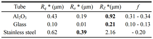
*Rz is the average of 10 measured data, and |

Two fluids are produced to simulate the flowing behavior of highly viscous melted glass and a Newtonian melt. The forces due to a friction from the wall of the tube (also called a barrel) and the nozzle of a ME module are measured and calculated in terms of the hydraulic pressure and external air pressure from an outer tank. Three other forces are also considered for the ME module using for hot extrusion.
The retarding force due to necking (reducing the cross section of the extrusion barrel) dominates the resistance to the flowing of fluids. When the diameter of the nozzle is small (e.g. 0.2 mm or 0.1 mm), the decrease in pressure in the tube, ΔP23 can account for 99% of the total resistance. It is necessary to apply a greater positive thrust (PT) to allow the fluid to flow continuously through the extrusion device.
For a fluid with a high viscosity (e.g. viscous S02-20 fluid), there is a friction force on the wall of the tube in an order of tens of Pa. During hot-extrusion, the viscosity of the melts decreases as the temperature and the shear rate are increased, so it is easier to extrude the molten materials of low viscosity at higher temperature. The simulation results show that it is more difficult to extrude viscous glass through very small nozzles with a 0.1 mm diameter.
The kinematic equations to describe the melt flowing through the tube and the nozzle are capable of describing the flow characteristics of fluids with high or low viscosity. For alumina tubes with a small nozzle diameter, the extrusion force that must be exerted by the feeding filament is in a range of few Newtons. This can be applied by a wire feeder capable of overcoming the resistance due to a reduction in the cross-section of the tube (the necking effect) and resistance due to the friction by the wall.
The authors thank the funding supported by Minister of Science and Technology in Taiwan by the contract no. MOST 105-2218-E-002-006. We also appreciate early effort of two master students, Mr. P. W. Wang and Z. S. Chou, to investigate related subjects, and helpful discussion with Professor S. J. Wang from Dept. Mechanical Eng., Southern Taiwan University of Technology is also appreciated.
- 1. W.C.J. Wei, ROC Patent No. CNS103 209734 (2014).
- 2. D.T. Pham and R.S. Gault, Int. J. Mach. Tool. Manu. 38[10-11] (1998) 1257-1287.
-

- 3. Y.T. Huang, W.C.J. Wei, Y.Y. Chen, and A.B. Wang, in the proceedings of the IEEE/SICE International Symposium on System Integration, SII 2017, December 2017 (IEEE, 2017)
- 4. N.C Fan, W.C.J. Wei, B.H. Liu, A.B. Wang, and R.C. Luo, in Proceedings of the 2016 IEEE International Conference on Industrial Technology, March 2016, (IEEE, 2016).
-
- 5. C.S. Chou, in “Applications and hot extrusion of Cu-based anode for SOFCs,” (National Taiwan University, 2015) p.1.
- 6. News, “Optical fibers provide new twist on traditional 3D printing process,” Ceramic Bull. 98[6] (2019) 11.
- 7. P.W. Wang, C.S. Chou, W.C.J. Wei, B.H. Liu, A.B. Wang, and R.C. Luo, in Proceedings of the 2016 IEEE International Conference on Industrial Technology, March 2016, (IEEE, 2016).
-
- 8. J.S. Reed, in “Principles of Ceramics Processing, 2nd ed” (Wiley & Sons, 1995)
- 9. J.J. Benbow, E.W. Oxley, and J. Bridgewater, Chem. Eng. Sci. 42[9] (1987) 2151-2162.
-
 This Article
-
2021; 22(3): 264-275
Published on Jun 30, 2021
- 10.36410/jcpr.2021.22.3.264
- Received on Mar 18, 2020
- Revised on Aug 4, 2020
- Accepted on Sep 4, 2020
Services
- Abstract
introduction
kinematic equation of extrusion
experimental
results and discussion
conclusion
- Acknowledgements
- References
- Full Text PDF
Shared
Correspondence to
- W.C.J. Wei
-
Dept. Mat. Sci. Eng., National Taiwan University, 106, Taiwan
Tel : +886 2 33661317 Fax: +886 2 23634562 - E-mail: wjwei@ntu.edu.tw
Clean-Energy Research Institute(CRI), Hanyang University, 222, Wangsimni-ro, Seongdong-gu, Seoul, 04763, Korea
E-mail: jcpr@hanyang.ac.kr