


- Experimental investigation on serpentine, parallel and novel zig-zag flow fields for effective water removal and enhanced performance on 25 cm2PEMFC
Muthukumar Marappana, Magesh Kannan Vijayakrishnanb, Karthikeyan Palaniswamyb,*, Karthikeyan Manoharanb, Thanarajan Kumaresanb and Jyothis Arumughanc
aFuel Cell Research Lab, Department of Mechanical Engineering, Nandha Engineering College, Erode-638052, India
bFuel Cell Energy System Laboratory, Department of Automobile Engineering, PSG College of Technology, Coimbatore 641004, India
cDepartment of Mechanical Engineering, Assam Engineering College, Guwahati - 781013, IndiaThis article is an open access article distributed under the terms of the Creative Commons Attribution Non-Commercial License (http://creativecommons.org/licenses/by-nc/4.0) which permits unrestricted non-commercial use, distribution, and reproduction in any medium, provided the original work is properly cited.
Water management is decisive in the commercialisation of Polymer Electrolyte Membrane Fuel cells (PEMFCs) as poor water management leads to reduced performance and reliability. Hence, this work deals with effective water management and physically examines water removed at cathode outlet in 25 cm2 PEMFC of land width by channel width of 2 x 2. Six combinations among flow fields such as parallel without slope, parallel with slope, serpentine and a novel parallel zigzag with slope are used for experimentation. Experimental results disclose that inducing cross flow among reactants, increasing exposure area of uncompressed MEA with reacting gases and backpressure increases the performance while slope at cathode increases the water removal rate of PEMFC. The novel flow field when used at the cathode with the serpentine flow field at anode accumulates advantages of the flow fields considered and enhanced the performance by about 23% than conventional serpentine flow fields due to the induced flow non-uniformity, under rib convection and better water removal rate. Additionally, to enhance the water removal and performance a silicon dioxide based ceramic ink is spray coated on the graphite plate to increase its hydrophobicity. As the electrical conductivity of silicon dioxide, a key constituent in the hydrophobic coating is limited, a blend of 2% graphene by weight with the ceramic ink is also attempted along with the durability of these flow fields for twelve hours of continuous operation
Keywords: Zig Zag Flow Field, Back Pressure, Slope in Flow Field, Cross Flow in Reactants, Ceramic ink coating, Durability Studies
Diminution of conventional fossil fuels and ecological contamination has turned the focus of research on alternate power generation systems. A large number of researchers are working on alternate fuels and power generation systems like fuel cells. Fuel cells are capable of producing green energy with little pollution and hence can be considered as a potential power generation device. When weighed against other types of fuel cells, Polymer Electrolyte Membrane Fuel Cells (PEMFCs) are more efficient and have high power density. Additionally, they are easy to install, can operate on relatively low operating temperature and pressure, respond dynamically to load and have a longer lifetime however the cost of PEMFC [1] is a major hindrance to commercialization. Also, water formed as a by-product of the electrochemical oxidation and reduction reactions is to be balanced [2] reasonably to avoid flooding and dehydration of membrane as they cause a reduction in power (poor performance) of the PEMFC. Accumulation of water is due to electro-osmotic drag from anode to cathode vide the membrane and back diffusion of water from the cathode flow field to catalyst sites causes flooding. Proper water management ensures that the membrane remains fully hydrated and maintains good ionic conductivity [3] leading to enhanced performance. Considering these facts a few pieces of research relevant to this work are discussed below.
Parallel and serpentine flow fields are predominantly used in PEMFC, efforts are made to enhance their performance by modifying their land width, number of channels, the shape of the flow path, orientation, etc. Diverse techniques have been adopted to tackle water management issues, out of which the flow field design is most noteworthy. Innovative flow channels were designed and tested to improve water management in PEMFC and demonstrated that channel cross-section design can be used to improve their performance [4, 5]. The ill effect of water accumulation was established by visualizing oxygen distribution and water blockages in an operating 3 pass-parallel-serpentine PEMFC [6]. Studies on flooding cathode channels of PEMFC and concluded that water accumulation in the flow field significantly reduces the performance [7]. Despite these issues, the serpentine flow field is endowed with superior power when compared to other conventional flow fields [8]. The consequence of porous inserts in ribs was established as a performance enhancer for PEMFC due to better water removal [9]. The perfor- mance of PEMFC with different gas path lengths on the serpentine flow field and concluded that shorter path length gives more performance and less condensed liquid water than the longer path [10]. On the other hand that relative analysis of various flow channel configurations shows that pressure drop of parallel flow channels is negligible compared to serpentine flow channels due to geometric uniformity [11]. Whereas, serpentine flow channels have a higher pressure drop and flow uniformity is higher for parallel flow channel which are barriers for further enhancement in power. The effect of flow field design on water lodging and concluded water accumulated however small, leads to large differences in the performance of fuel cell due to an increase in ohmic resistance [12]. The parallel flow field establishes better performance for long flow channels [13]. An increase in field width enhances the water removal and increases in height cause pressure drop and accumulation of liquid water at the outlet in PEMFC [14]. Channel height has a significant effect on performance [15]. The parallel flow field with step-wise depth appreciably increases the PEMFC performance [16]. Meanwhile, the serpentine flow field remains insensitive to depth variations in design. They inferred the balancing of pressure at anode and cathode side as a reason for the same.
Back Pressure (BP) another significant parameter which influences the performance of PEMFC is discussed below. Backpressure increases the performance of PEMFC after studying the serpentine and interdigitated flow channels with various land to channel widths. The land width by channel width of 2 ´ 2 mm is ideal owing to superior water removal, although there is a marginal drop in performance when compared to land width by channel width of 1 ´ 1 mm [17]. Backpressure is one of the key parameters which influence their performance. This increase in performance is a result of forcing reactants against catalyst sites [18]. The performance of fuel cells increased when backpressure in the flow channels is increased due to an increase in residence time of reactants in the channel [19, 20]. Change in cell voltage due to backpressure is because of the variations in the properties including exchange current densities, membrane conductivity and mass transfer [21].
Flow non-uniformity and distribution are important parameters that influence PEMFC’s performance, previous researchers about the same are discussed herewith. Flow non-uniformity caused in flow channels will improve the performance of parallel flow channels [22]. Baffle design or inducing flow non-uniformity yields better performance than the conventional serpentine flow channel [23]. Nominal flow misdistribution had mild flow variation and was found to perform better than channels with high misdistribution [24]. Improved flow distribution among flow channels will improve their performance [25]. Funneled entry and exit at 45o makes flow uniform across flow channels [26].
From the literature surveyed the importance of the design of flow field, back pressure, channel height, water management, inducing nonuniformity in the flow of reactants, in enhancing the performance of PEMFC is evident. With due importance to water removal and performance, this study uses the serpentine and parallel flow field for better dispersion of reactants and better water removal respectively. Taking into account, the influence of pressure drop and depth of flow channel on performance, this study uses different flow fields with a slope such that the depth increases along the length of the flow. Owing to the positive effect of BP a study on the same is also included.
The originality of this paper lies in reducing flooding in PEMFC by inducing a slender slope of 2 mm and enhancing the performance by adopting a novel zigzag pattern at the cathode flow field. A gradual slope is induced in the cathode flow field as abrupt steps (as in literature survey) are likely to affect the structural stability of the MEA. Flow non-uniformity can be induced by zigzag configurations in each channel and inverted funneled gas entry and exit at 45o will make flow uniform across flow channels. Experimental analysis is done for various flow fields including a novel parallel zig-zag flow field with slope at the cathode, and serpentine flow field at the anode which is capable of combining the advantages of serpentine and parallel flow fields. The change in performance due to this design modification is examined. The quantity of water emerging from the cathode outlet is measured by the absorption technique. The quantity of water removed from PEMFC is related to the performance. Hence, the water removal rate is measured as a ratio of the weight of water removed from cathode outlet to the corres- ponding maximum power density of PEMFC is a novel method adopted in this paper capable of predicting PEMFC’s durability for long-running hours.
Due to the pressure exerted during assembly of PEMFC, the porosity of the GDL at land-over-land interfaces is less than that of the land-over-channel interfaces or vice versa. The pores in the GDL acts as micro siphons and move water from the land to the flow channel. Therefore, the reduced porosity reduces the siphoning effect. Hence, the study also attempts to disclose the effect of the area of uncompressed MEA on the performance of PEMFC.
A Bio-Logic FCT-50S test station is used for experimental analysis. FC-Lab V.5.22 software interfaced with the test station controls the operating parameters of PEMFC as defined by the user. The test station is competent in reading electrical parameters to a maximum of 5 V, 50 A and 250 W: and flow rates to a maximum of 1.5 lpm and 1.0 lpm at anode and cathode sides respectively. A commercially available Nafion 212 membrane is used in all experimental analysis. The MEA consists of a five layer assembly such as GDL or diffusion medium of size 5 cm ´ 5 cm coated with 20% Pt/C which acts as the catalyst with a loading of 0.5 mg/cm2 of Pt on both anode and cathode sides. The Nafion 212 membrane is sandwiched with a catalyst coated GDL with the catalyst coated side facing the membrane on either side. Hot pressing is done at 120 oC [27] at a pressure of 50 kgf/cm2 for 3 min. Pure hydrogen (99.99%) and oxygen are used as reactants at the anode and cathode sides respectively. Gold coated copper plates are used at anode and cathode sides as current collectors.
The MEA has a critical function in the power production, but many sites in the MEA remain inactive and lead to the poor performance of PEMFC. Thus conditioning is to be done to activate all the sites in the MEA and increases the performance. Conditioning of MEA is done by voltage and current pulsing for enhancing the proton conductivity of the membrane.
Voltage Pulse: It applies constant voltage for a specified amount of time. In this work, voltage pulsing is done by maintaining 0.5 V for 20 min followed by 0.7 V for 20 min. Voltage pulsing is repeated until the current attains its peak value in the respective voltage.
Current pulse: It applies constant current for a specified amount of time. In this work, voltage pulsing is done by maintaining 5 A for 20 min followed by Open Circuit Voltage (OCV) for 1 min this set was repeated after one set of voltage pulsing [7] have adopted a similar procedure for conditioning of MEA.
Even after conditioning, irreversible losses cause an unavoidable drop in voltage from the reversible voltage. Voltage is scanned from 1 V or 0.9 V to a limiting voltage with a scan rate of 0.2 mV/s with a hydrogen flow rate of 500 ml/min at anode and an oxygen flow rate of 250 ml/min at the cathode.
The cell temperature, humidifier temperature and line temperature at both anode and cathode are maintained at 60 oC. The anode and cathode stoichiometry are maintained at 2.11 for all the experiments with reference to a maximum current density of 1.1 A/cm2 (attained during the trials conducted). To get rid of experimental uncertainties three trials are conducted and the mean of the three was considered for analysis.
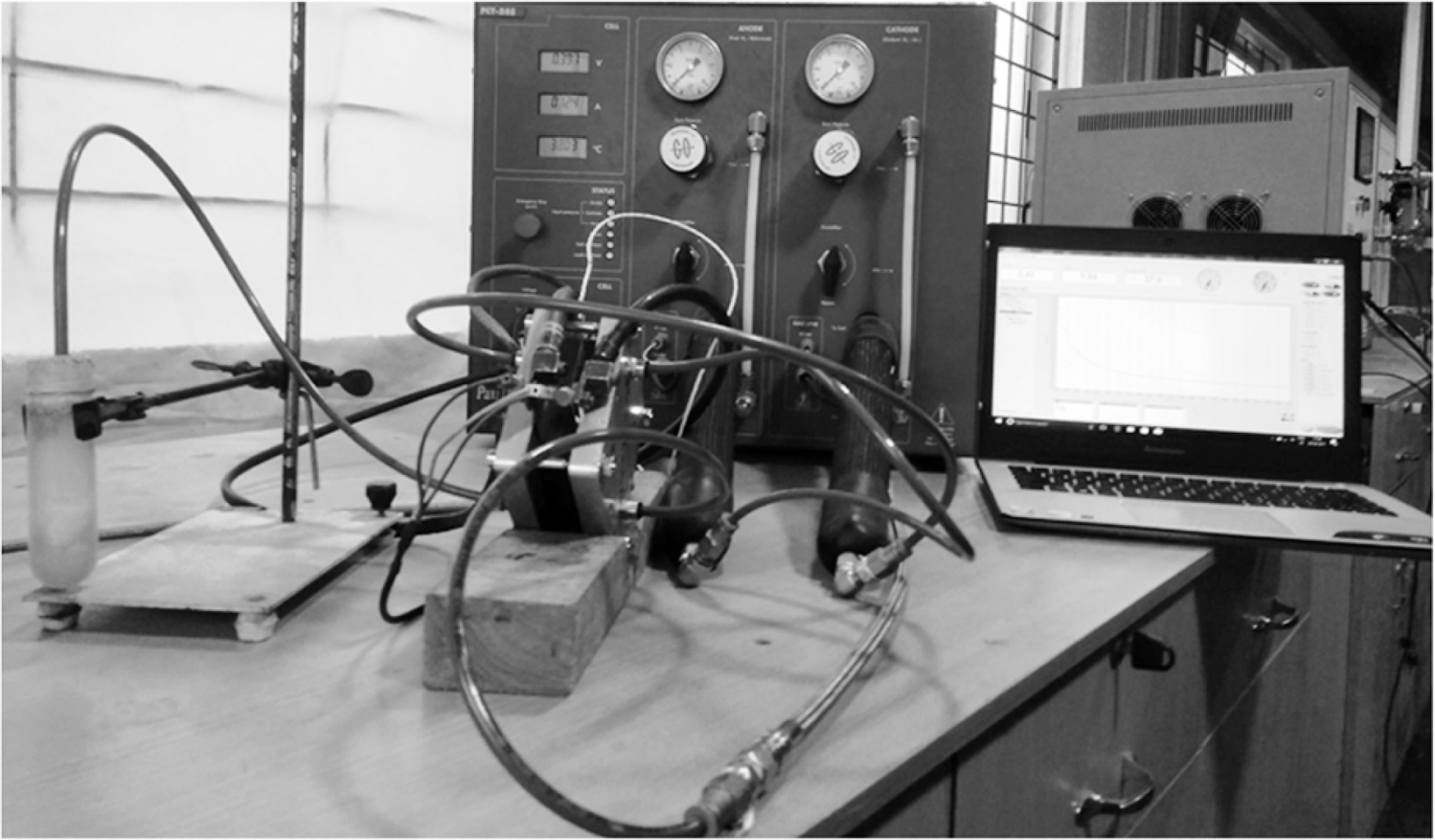
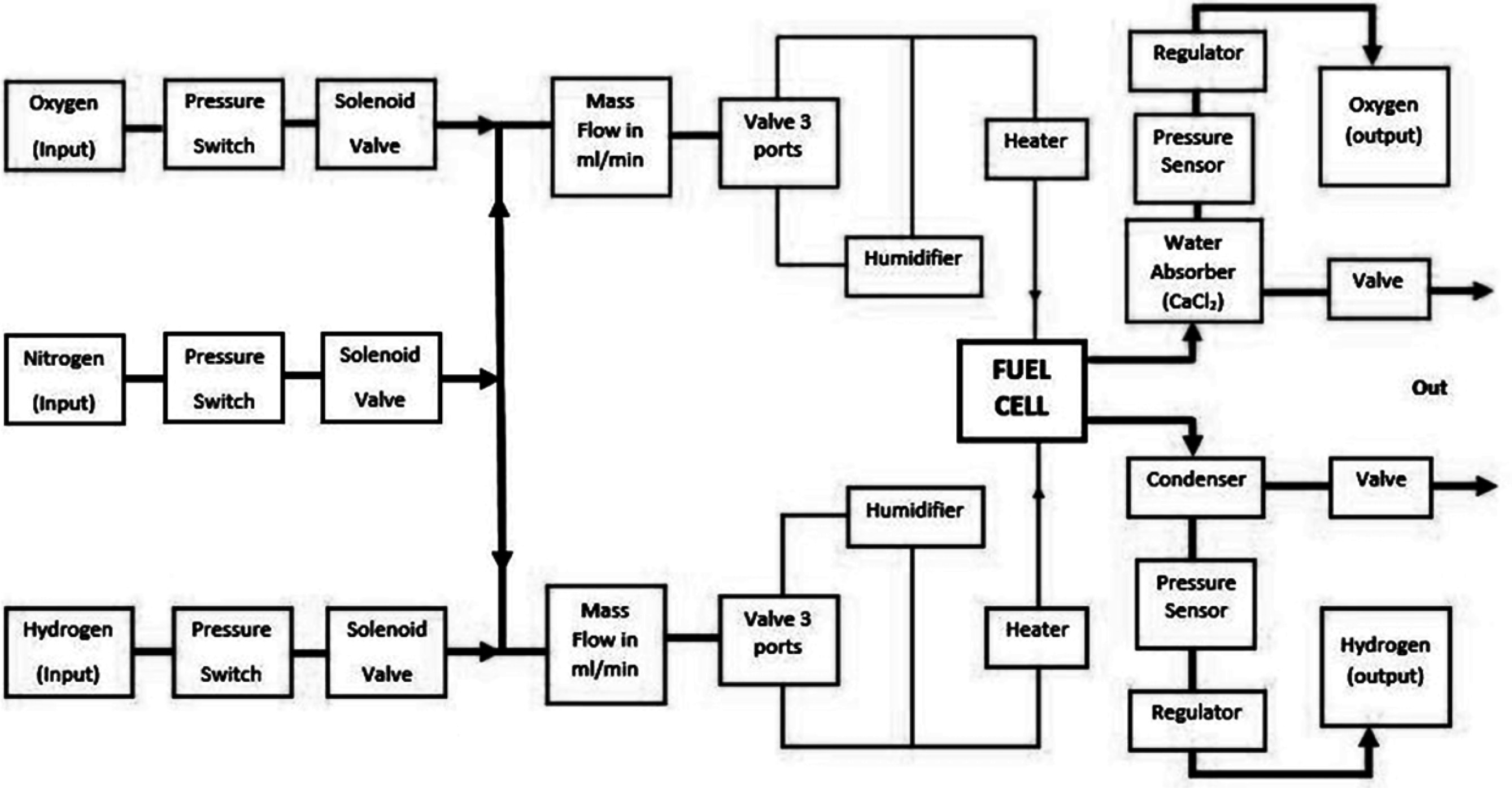
The water removed from all flow fields considered is assessed with the same scan rate. The water leaving PEMFC during the voltage scan period is measured using the absorption technique. As the weight of the complete fuel cell assembly measures up to 0.68 kg measuring a small quantity of water may not be that accurate, moreover measuring the weight of the PEMFC assembly will give the quantity of water accumulated in PEMFC, and this work assesses the quantity of water removed from PEMFC. Calcium Chloride (CaCl2) a soluble, deliquescent and hygroscopic salt is used for water absorption in this technique. The salt is preheated in a hot-air oven of about 110 oC for 1 h to remove the moisture already present. A previously weighed quantity of CaCl2 is kept in a test tube and a hose is connected from the outlet of the cathode to the bottom of the test tube such that the gas flowing out of cathode passes through CaCl2 before exhausting to the atmosphere. This causes a resistance to the outgoing gas, the same as measured by a pressure transducer was found to be about 1.5 bar. The same BP is induced at the anode side outlet to equalise pressure on both sides of the membrane. The test setup used for experimentation and layout of the test station is shown in Fig. 1 and Fig. 2 respectively.
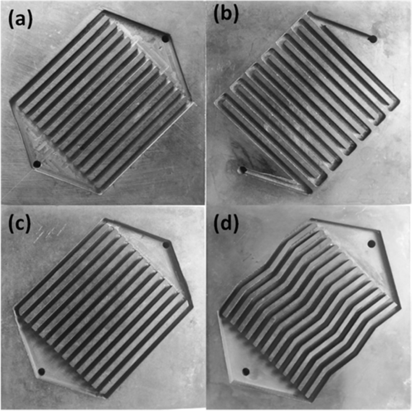
This study comprises of experimentations with and without BP using six combinations of flow fields such as serpentine flow fields at anode and cathode (SS), parallel flow fields without slope at anode and cathode (PP), parallel flow field without slope at the anode and parallel flow field with slope at the cathode (PPS), serpentine flow field at the anode and parallel flow field without slope at the cathode (SP), serpentine flow field at the anode and parallel with slope at the cathode (SPS) and serpentine flow field at anode and parallel zig-zag with slope at the cathode (SPZS). The same is shown in Fig. 3.
Design modification on the cathode flow field
The design considered in this work induces a gradual slope from inlet to the outlet at the cathode. This increases the volume of the flow field as the reactants advance hence, a pressure drop is induced. The slope or hydraulic gradient of 2 mm persuades water to move towards the outlet. This design prevents back diffusion from the cathode flow channel to catalyst sites due to the concentration gradient. Hence the introduction of a mild slope at the cathode is likely to increase the performance of PEMFC. The depth of the flow channel at the inlet and outlet is 2 mm and 4 mm respectively for a slope of 2 mm. The slope cannot be increased further as the flow plate selected for experimentation is 5 mm thick. This work experimentally analyses the effect of zig-zag flow channels with conventional flow channels, in this process, the distance for lateral diffusion must be kept constant (i.e.) the rib size has been matched maximum distance through which the reactant has to travel at the last rib. Hence the bend in each channel is approximately 10o. This modification made in the design increases the resident time of the oxidant at the cathode when compared to the parallel flow field. The zig-zag pattern will induce flow non-uniformity and under rib convection in the flow channel enhancing the performance further. As discussed earlier an inverted funneled gas entry and exit at 120o is adopted in all parallel flow fields to make flow uniform across flow channels. This design is evaluated against the serpentine flow field and uses an active area 25 cm2 as most literature exploits the same.
|
Fig. 1 Bio-Logic FCT-50S test station interfaced with FC-LabV.5.22 and CaCl2 water absorbent at cathode outlet used for experimentation. |
|
Fig. 2 Layout of fuel cell test station. |
|
Fig. 3 Flow fields used for performance studies on 25 cm2 PEMFC (a) parallel flow fields without slope (b) serpentine (c) parallel flow fields with slope and (d) parallel zig-zag with slope. |
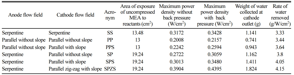
Experimentation is done in Bio-Logic FCT-50S test station interfaced with FC-Lab V.5.22 software. Six configurations of flow fields with and without a fairly accurate BP of 1.5 bar are experimented. The polarization curves and performance characteristics are presented for all configurations considered. Initially, activation loss is high in all cases causing a steep decrease in voltage [28]. All trials are conducted for flow fields with a rib width by channel width of 2 x 2 mm [17], an active area 25 cm2 and a physical slope of 2 mm. The inlet of anode and cathode flow fields are always positioned on the top for gravity assisted flow. The key features of the six flow field combinations considered are tabulated in Table 1.
The influence of various factors leading to a rise in performance is discussed in the following sections.
Influence of parallel flow in reactants
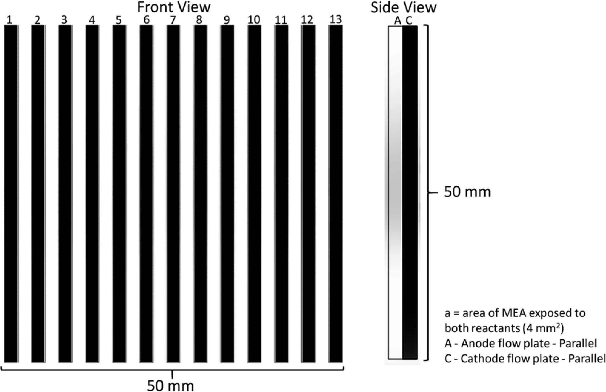
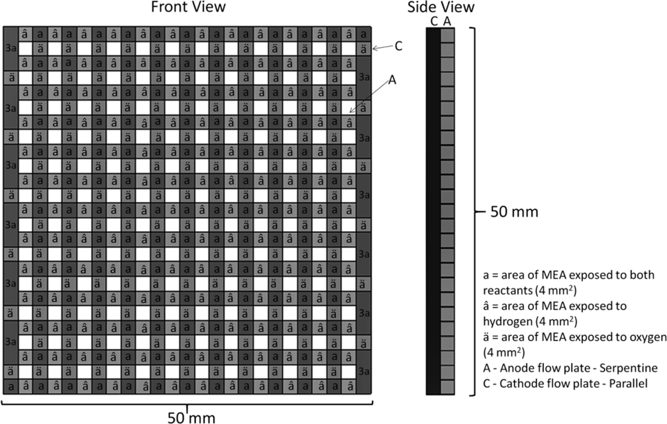
Experiments on serpentine and parallel flow fields reveal the influence of parallel flow in reactants. Both flow fields are assembled in such a way that the flow channels of anode and cathode are directly facing each other as shown in Fig. 4 where ‘a’ represents 4 mm2 areas. The area of exposure of uncompressed MEA calculated according are 13 cm2 in PP and 13.48 cm2 in SS.
Although the area of direct interaction with the reactants is almost the same in PP, the rate of reaction is less as the time spent by the reactants in the flow field is less since the distance is traveled by the reactants from inlet to outlet is much less in PP compared to SS. Hence the maximum power developed in PP is lower than SS. The flow of reactants within the flow field in a parallel flow field is uniform [11] hence the probability of interaction with the catalytic active area is less. This is another rationale for lower maximum power.
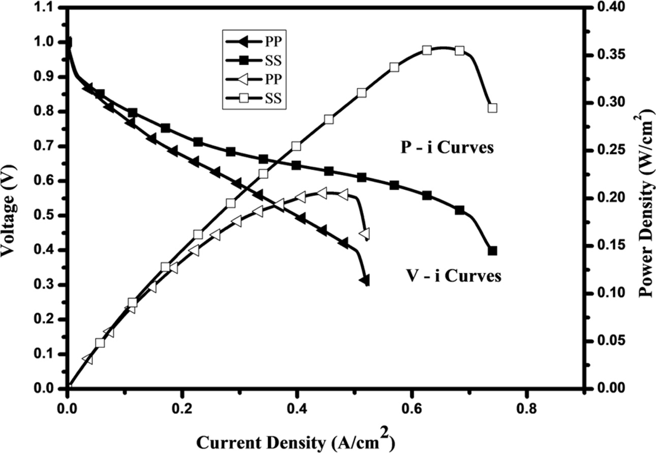
Fig. 5 shows the polarisation curve (V-i Curves) and performance characteristics (P-i Curves) for PP and SS flow field configurations without BP, it can be noticed that the power density of serpentine flow field is 0.3172 W/cm2 which is about 58% more than that of the parallel flow field. The time spent by reactants in the serpentine flow fields is more and flow becomes non-uniform due to bends [11] consequently the maximum power is more than that of the parallel flow field.
When both flow fields are serpentine without slope the reaction rate and formation of water are maximum near the inlet and gradually decrease as we move towards the outlet as the molar concentrations of the reactants are more at the inlets. This accumulation of water acts as a barrier to the performance of PEMFC due to back diffusion of water to the catalyst sites, as the concentration gradient is more at the cathode flow channel. Although the serpentine flow field generates more power than the parallel flow field quantity of water removed from the cathode flow field is less relative to the power produced. The following sections discuss modes by which these barriers are overcome.
Influence of cross flow in reactants
The power produced by the serpentine flow field is more and the water removal rate of the parallel flow field is more so an attempt is made with the serpentine anode flow field and parallel cathode flow field (SP) this simulates a cross flow between reactants. The assembly of the same is shown in Fig. 6. In this arrangement, the area of uncompressed MEA which is exposed to both reactants gases is 7.24 cm2 and the area exposed to the hydrogen at anode and oxygen at the cathode are 6 cm2 each. At sites where the MEA is exposed to one reactant, the other side faces land area, but the compression can be negligible due to the elasticity of the membrane. Hence, the overall area of exposure uncompressed MEA is at 19.24 cm2 which is higher than the other combinations considered.
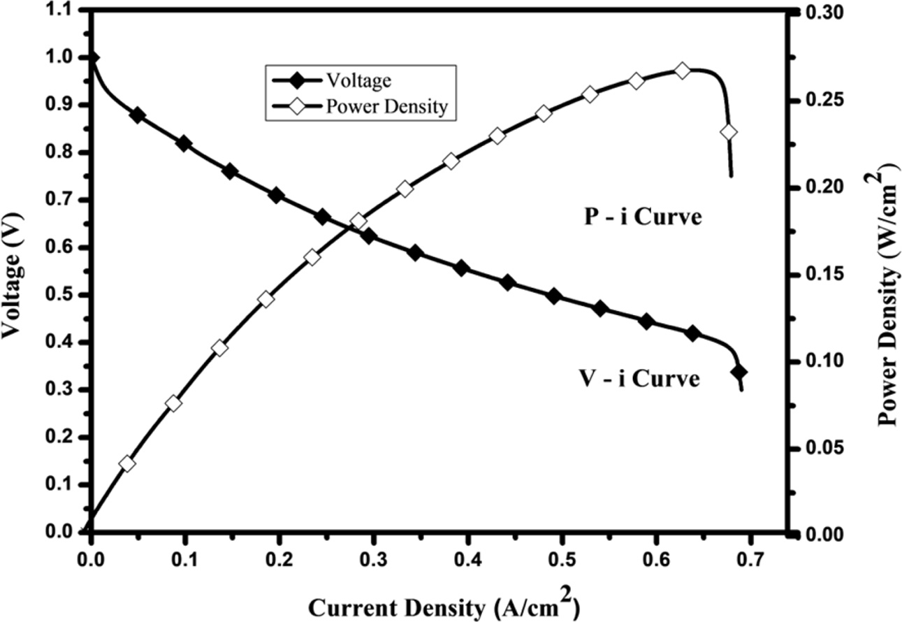
Interchanging the anode and cathode flow fields is not preferred as a parallel flow field at anode produces less power and the serpentine flow field at cathode removes less water. The polarisation curve and perfor- mance characteristic for SP flow field configurations without BP are shown in Fig. 7.
The performance of the SP flow field is 26.23% better than PP due to better exposure of reactants at the catalyst sites as the porosity of GDL is high, for a larger area than PP, aiding better diffusion. The power density of SP is 0.2722 W/cm2 which is 14.19% less than that of SS without BP. The performance of SP is less than SS despite better water removal and higher exposed area because the resident time in the cathode flow channel is less. To increase the reaction rate further the resident time is to be increased, methods of addressing the same are discussed in the following sections.
Influence of slope in flow field
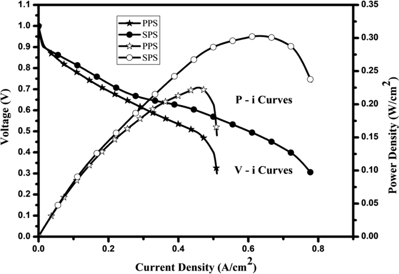
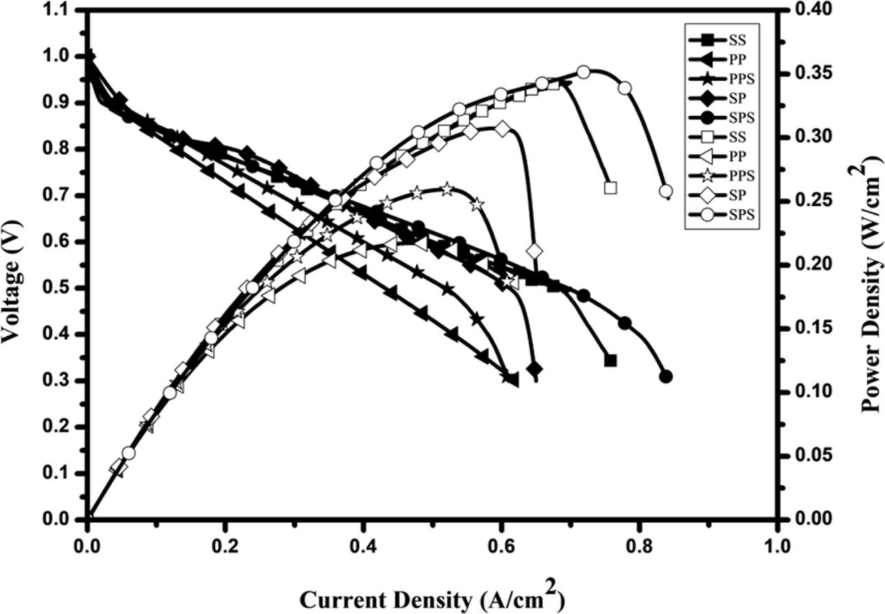
To moderate the problem of flooding in PEMFC without compromising on performance, a novel scheme of incorporating a slope (hydraulic gradient) on the cathode flow field is experimented. The assemblies of PPS and SPS are similar to PP and SP except for slope at the cathode. The introduction of slope induces a pressure drop that extracts water from the land area to the flow channel by siphoning effect leading to reduced water lodging in land area. The physical and velocity gradients aid movement of water from inlet to outlet causing less water accumulation in flow channels. The effect of gradient and siphoning collectively increases the performance of PEMFC. A mild slope of 2 mm is selected due to geometric limitations. The graphite plate used for machining the flow channels is only 10 mm thick. When the depth of the flow channel is more than 4 mm the structural stability of the graphite plate reduces during fastening at 4 Nm. Hence, the slope is restricted to 4 mm. Among flow fields studied, 11.65% increase in power density is seen in PPS from PP and 10.69% increase in power density is observed in SPS from SP. The performance of SPS is marginally less than SS, the performance of flow fields with slope are shown in Fig. 8 and those without slopes are shown in Fig. 5 and Fig. 7.
At cathode due to the increase in the volume of the flow channel, the reactant is slowed down and a pressure drop is induced. For SP configuration, the pressure drop at the anode is greater than at cathode. This reduces the reaction rate as hydrogen ions are moving from low pressure region to high pressure region. However, for the SPS configuration, the slope induced increases the pressure drop at the cathode thereby lowering the pressure difference from anode to cathode compared to SP. This causes a higher reaction rate due to increased electro-osmotic drag and proton conductivity. Despite this fact the performance of SPS is marginally low when compared to SS as the resident time at the cathode flow channel is still low and the flow is uniform at the cathode side. To increase the performance the velocity of flow is to be decreased further and flow uniformity at the cathode side is to be disturbed.
Influence of back pressure
The increase in power density due to BP alone in PP and SS is 7.42% and 8.07% respectively whereas a 12.38% increase is seen in SP. The enhancement in power density of PP and SS (parallel flow configuration) due to BP is less when compared to SP (cross flow configuration) due to higher porosity and longer mass transfer path through the GDL [29]. The area of exposure between the uncompressed MEA & reactants is only 13 cm2 in PP and 13.48 cm2 in SS but the same in SP is 19.24 cm2. Due to BP, the gases get squeezed towards the membrane compelling it to react. The increase in performance is directly related to the area of exposure. The polarisation curve (V-i Curves) and performance characteristics (P-i Curves) for different serpentine and parallel flow field configurations with and without BP are given in Fig. 9.
The mean increase in power density of flow fields considered was 11.94% due to BP. This result is expected as an increase in BP is likely to increase power density and increase the cell voltage [19, 21]
Influence of back pressure and slope in flow fields
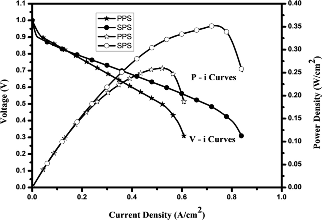
Experimental investigation reveal that slope induced flow fields produce better power density than conventional flow fields, moreover, a greater positive effect is seen in slope induced flow channels due to BP. Slope slows down the reactants along with the flow, whereas BP slows down and pushes the reactants towards the catalyst at the membrane electrode interface forcing it to react. This increases the resident time of reactants which in turn increases the power density due to the combined effect of BP and slope from the flow field discussed in the previous sections. The influence of BP and slope in flow fields on power density is quantified in this section. The polarisation curve and performance characteristics for PPS and SPS flow field configurations with BP are shown in Fig. 10.
BP enhanced the performance of PP and SP by 7.42% and 12.38% respectively whereas the increase in performance in slope induced flow fields such as PPS and SPS with BP is seen at 15.7% and 15.5% respectively. Both BP and slope individually increase the performance, however not cumulative their combined effect promotes the performance of PEMFC.
Influence of water removal rate
The water removal rate in flow fields are noteworthy in PEMFC as flow fields that have greater water removal rate are more suitable for continuous operations. The present study reveals that the water removal rate is apparent in flow fields with slope. A 5.81% increase is seen in the water removal rate of PPS while comparing PP, similarly, 6.58% raise is noticed in the water removal rate of SP with respect to SPS. The water removal rate of SS and SPS should also be compared as SS is the most common type of flow field in the literature surveyed. A 21.26% increase is observed while evaluating the water removal rate of SPS against SS. This is a highly ideal character because during long running hours water tends to accumulate in the flow channel and land surfaces, reducing the performance of PEMFC. Owing to higher water removal rate SPS is highly suitable for continuous operation. It is also noticeable that the performance of SPS is slightly greater than SP. The experimental results furnish a clear observation of the positive trend between slope and water removal rate in PEMFC. Hence, further studies are carried out incorporating slope at the cathode.
Effect of a novel zig-zag pattern on performance
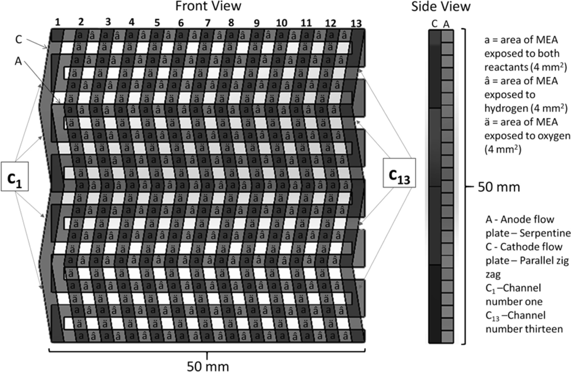
The novel zig-zag pattern with slope (SPZS) is selected for inducing flow non-uniformity, higher resident time and better water removal. The assembly of SPZS is shown in Fig. 11. It is also notable that the area of exposure of uncompressed MEA to reactants is as same as SP and SPS the area lost in channel one (C1) is gained in channel thirteen (C13) or vice versa. Hence, the increase in performance achieved by SPZS is not influenced by area when compared to SP and SPS. By inducing BP, incorporation of slope and adopting zig-zag pattern, the power density of PEMFC is enhanced.
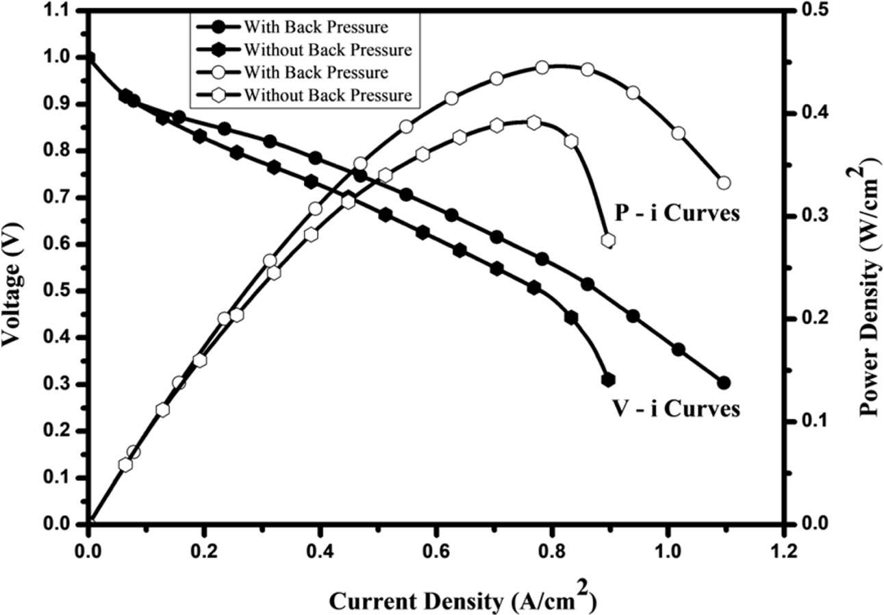
Zig-zag pattern induces non-uniformity of the flow thereby increasing the consumption of reactants along the length of the flow by directing the oxidant in the direction normal to the direction of flow (under rib convection) into the GDL which enhances the power density. This results in better proton conductivity, at the same time sharp bends that cause a pressure drop in the serpentine flow field are absent in the zig-zag flow field, hence the pressure drop of the zig-zag flow field is less. A 23.74% improvement in performance was evident because of enhanced under rib convection [18, 30]. The serpentine flow field is completely contained within the active area whereas zigzag flow fields are contained mostly within 5 cm ´ 5 cm area superimposed by the MEA. However, a small portion extending up to 2 mm in the first and last flow channels is not covered by MEA, this may not cause a loss in the area if gas diffusion is accounted. Despite this drawback, zigzag flow fields have better performance than serpentine flow fields. Numerical analysis of zig-zag flow fields without slope also reports an increase in performance [31]. Another advantage of the zig-zag flow field is the increase in cross channel diffusion of oxidant between consecutive flow channels; this will move water from the land area to the flow channels. The flow of oxidant along with the gradient induced will move water towards the outlet thereby increasing the performance. Polarisation curves and performance characteristics for SPZS flow field configurations with and without BP is revealed in Fig. 12.
The combined effect of BP, incorporation of slope and adopting zig-zag pattern enhance the performance of PEMFC. The power density of SPZS is 0.3904 W/cm2 and 0.4395 W/cm2 without and with BP respectively. In correlation with the above, the increase in power density with respect to the novel SPZS flow field with respect to SS is 23.08% and 28.21% without and with BP respectively. The enhancement in power density relating to SPS is 29.57% and 26.29% respectively without and with BP respectively. Also, the transverse direction pressure loss is minimum in the zigzag flow field [31]; this leads to better consumption of reactants on catalyst sites. Additionally, proton conductivity, improved under rib convection, flow non-uniformity and effective water removal at cathode flow field pave way for enhanced performance. This significant rise in power density along with better water removal characteristics [32] will make PEMFC more reliable for continuous operations. Better water removal is achieved since water formed on ribs is transported to the channel by inter channel diffusion due to the difference of pressure in subsequent channels. This phenomenon is accelerated in the zig-zag flow field as water formed on the inclined rib facing the flow will be pushed to the next channel, in this manner removing more water than other flow fields.
Effect of ceramic ink coating
As water removal enhances the performance of PEMFC another attempt is made to further increase water removal from the flow field by spray coating proprietary silicon dioxide based ceramic ink, which is on the graphite plate to increase its hydrophobicity. As the electrical conductivity of silicon dioxide, a key constituent in the hydrophobic coating is limited, a blend of 2% graphene by weight with the ceramic ink is also attempted.
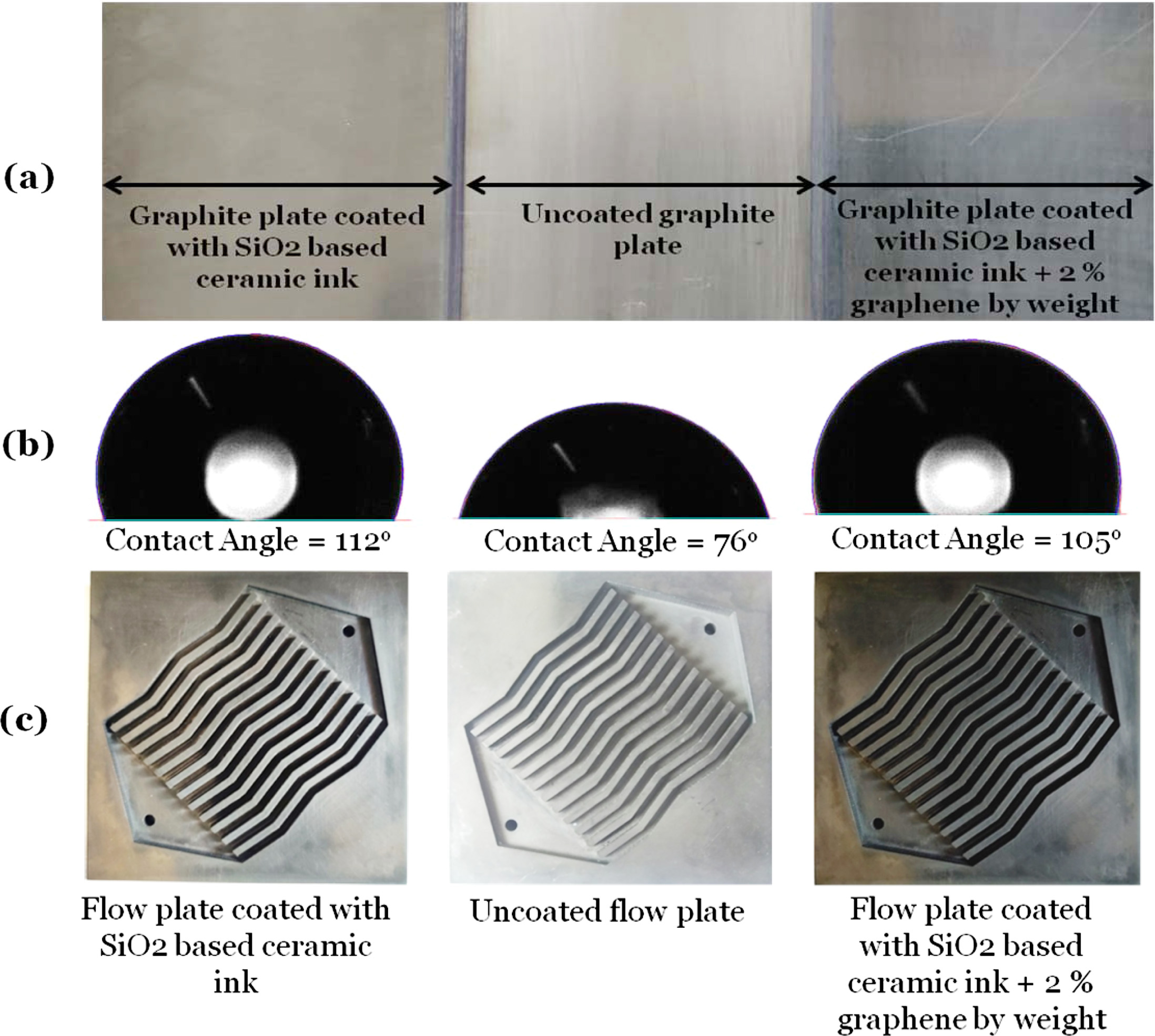
The uncoated graphite plate (SPZS), and graphite plate coated with ceramic ink [33] (SPZS+CC) and ceramic ink blended with 2% graphene (SPZS+CC2%) (Fig. 13(a)) were tested for contact angle using a contact angle meter (OCA 20, Dataphysics, Germany) with 10 microliter of ultrapure water at five different locations [34] on the plate after resting the droplet for 30 minutes [35]. Their average contact angles rounded down to the next integer are 76o, 112o and 105o respectively (Fig. 13(b)). This indicates that the uncoated graphite plate is hydrophilic causing retention of water and thereby leading to flooding. On the other hand, the ceramic ink coating makes the graphite plate hydrophobic facilitating water removal. In order to substantiate this claim and to check it’s compatibility in PEMFC the silicon dioxide based ceramic ink was spray coated on the side of the flow plate facing the MEA (Fig. 13(c)) this coating was done at the cathode side only.
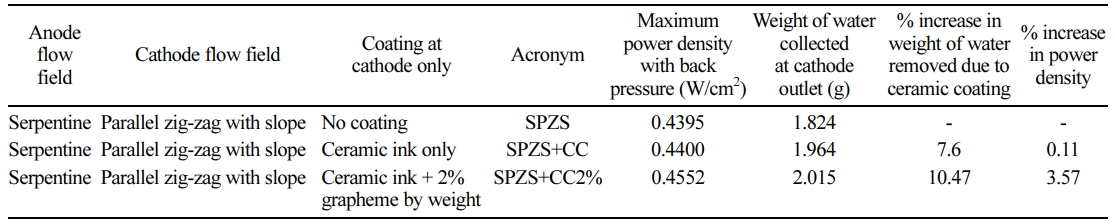
The performance of the coated novel SPZS flow fields was compared with the uncoated flow field. The coated flow fields could remove more water from the flow channels than the uncoated flow field. However, the increase performance seen in the flow field coated with only ceramic ink was insignificant whereas a notable increase in performance was observed in the flow field coated with a blend of 2% graphene and ceramic ink. The water removal and power density of coated and uncoated novel flow fields are presented in Table 2.
An increase of 10.47% was seen in the quantity of water removed in SPZS+CC2% with respect to SPZS while the corresponding value in comparison with SPZS+CC was 7.6%. On the other hand, 3.57% increase was seen in the maximum power density of SPZS+ CC2% with respect to SPZS while the corresponding value in comparison with SPZS+CC was only 0.11%. This enhancement in water removal was due to the hydrophobic coating. As water removal increases the performance of PEMFC should also increase [36, 37], contrary to this, despite better water removal, a notable change in performance was not seen, this is because the electrical conductivity of the ceramic ink is low. In agreement with this when 2% graphene (a substance with higher electrical conductivity) is added, the increase in performance is notable performance.
Durability Studies
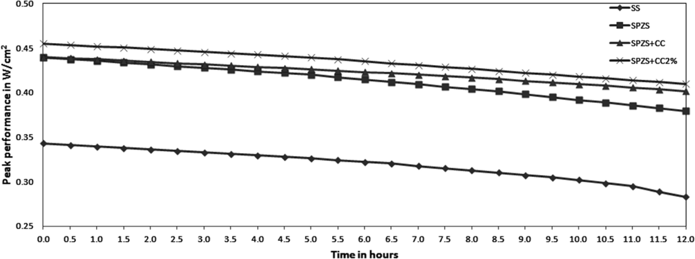
To justify the durability [38] of the novel serpentine-zigzag flow field, the experimental analysis was carried out for 12 h continuously, the peak performance of the serpentine flow field was compared serpentine-zigzag flow field configurations with and without coating. The results revealed that the peak performance of all these flow field configurations did not change significantly for the first five hours (less than 5% drop from the initial value). Beyond which the performance starts deteriorating further, however, the rate at which peak performance of SPZS flow field configuration drops is lower than the drop in SS flow field configuration. After twelve hours of continuous operation, the peak performance of the SS flow field had dropped by 17.5% whereas the SPZS flow field had dropped by 13.7% only. This indicates that SPZS is more durable for long operating time. Similarly, the performance of SPZS+CC and SPZS+CC2% witnessed 8.7% and 9.9% drop in peak performance. The drop in performance in coated floe fields is lower because of better ware removal. The peak performance at 0.5 hour time in travel is given in Fig. 14.
|
Fig. 4 Front and side views of PP and SS flow field assemblies |
|
Fig. 5 Performance characteristics (P-i Curves) and polarisation curve (V-i Curves) for parallel flow (PP and SS flow field) configurations without BP. |
|
Fig. 6 Front and side views of SP flow field assembly. |
|
Fig. 7 Performance characteristics (P-i Curve) and polarisation curve (V-i Curve) for SP flow field configurations without BP. |
|
Fig. 8 Performance characteristics (P-i Curves) and polarisation curve (V-i Curves) for PPS and SPS flow field configurations without BP. |
|
Fig. 9 Performance characteristics (P-i Curves) and polarisation curves (V-i Curves) for different serpentine and parallel flow field configurations with BP. |
|
Fig. 10 Performance characteristics (P-i Curves) and polarisation curves (V-i Curves) for PPS and SPS flow field configurations with BP. |
|
Fig. 11 Front and side view of SPZ flow field assembly |
|
Fig. 12 Performance characteristics (P-i Curves) and polarisation curve (V-i Curves) for SPZS flow field configurations with and without BP |
|
Fig. 13 (a) Graphite plate with and without coating, (b) Contact angle of a water droplet on the graphite plate with and without coating and (c) SZS flow plate with and without coating |
|
Fig. 14 Performance evaluation for twelve hours of continuous operation |
|
Table 1 Water removal rate and maximum power densities of the six flow fields considered for performance analysis of 25 cm2 PEMFC. |
|
Table 2 Water removal and power density of coated and uncoated novel flow fields. |
• Decreasing the area of MEA compressed on both sides while inducing back pressure and flow non-uniformity at the cathode while using SPZS yields better performance in PEMFC.
• Inducing a slope at cathode increases the perfor- mance of PEMFC by 11.17%.
• BP positively influences the performance of PEMFC. The increase in power density in flow fields without slope due to BP is 9.29%. The effect of back pressure is more in flow channels with a slope where 14.59% enhancement in power density was observed.
• Flow channels with slope can remove water at a better rate than their counterparts without slope. Comparing the water removal rate of SS and SPS, 21.6% more water removal is achieved in SPS.
• The novel SPZS gives higher power density and is more durable for long operation time than the other variants studied. Rise in power density compared to its nearest contender SPS is at 26.29% with backpressure and the analogous value with SS is 23.08% without BP. The rise in performance is due to better interaction with reactants due to diffusion of reactants normal to the flow (under rib convection) and non-uniformity of the flow, leading to enhanced reaction rate and higher water removal.
• SPZS+CC is capable of removing more water than other flow fields considered, but its performance did not increase with respect to SPZS due to lower electrical conductivity of the coating, on the other hand, the performance SPZS+CC2% was marginally better than SPZS owing to better electrical conductivity due to the addition of graphene and higher water removal due to the hydrophobicity of the coating with respect to SPZS. This also increases the durability of this flow field.
• In future, the effect of varying the weight of graphene could be optimized and superhydrophobic coatings can be attempted.
The authors wish to thank DST-UKIERI (DST/INT/UK/P121/2016; Dated 11.07.2017), TEQIP III & NPIU-CRS; Dated 18 June 2019 for providing the necessary funding and support to carry out this work.
- 1. B.S. Koh, J.H. Yoo, J.H. Kim, and S.C. Yi, J. Ceram. Process. Res. 17[4] (2016) 332-337.
- 2. S.J. Lee, S. Shin, J.H. Yoo, and S.C. Yi, J. Ceram. Process. Res. 18[9] (2017) 666-670.
- 3. M. Karthikeyan, M. Muthukumar, P. Karthikeyan, and C. Mathan, J. Ceram. Process. Res. 20[5] (2019) 490-498.
-

- 4. N. Bunmark, S. Limtrakul, M.W. Fowler, T. Vatanatham, and J. Gostick, J. Power Sources 35[13] (2010) 6887-6896.
-
- 5. J. Zhang, H. Li, Z. Shi, and J. Zhang, Int. J. Green Energy 7[5] (2010) 461-474.
-
- 6. K. Takada, Y. Ishigami, J. Inukai, Y. Nagumo, H. Takano, H. Nishide. and M. Watanabe, J. Power Sources 196[5] (2011) 2635-2639.
-
- 7. A. Su, F.B. Weng, C.Y. Hsu, and Y.M. Chen, Int. J. Hydrogen Energy 31[8] (2006) 1031-1039.
-
- 8. L. Rostami, P.G. Nejad, and A. Vatani, Energy 97 (2016) 400-410.
-
- 9. P. Karthikeyan, R.J. Vasanth, and M. Muthukumar, Int. J. Hydrogen Energy 40[13] (2015) 4641-4648.
-
- 10. S. Shimpalee, S. Greenway, and J.W.V. Zee, J. Power Sources 160[1] (2006) 398-406.
-
- 11. S. Maharudrayya, S. Jayanti, and Deshpande, J. Power Sources 157[1] (2006) 358-367.
-
- 12. J.P. Owejan, T.A. Trabold, D.L. Jacobson, M. Arif, and S.G. Kandlikar, Int. J. Hydrogen Energy 32[17] (2007) 4489-502.
-
- 13. J. Bachman, M. Charvet, A. Santamaria, H.Y. Tang, J.W. Park, and R. Walker, Int. J. Hydrogen Energy 37[22] (2012) 17172-17179.
-
- 14. K.S. Choi, H.M. Kim, and S.M. Moon, Int. J. Hydrogen Energy 36[2] (2011) 1613-1627.
-
- 15. A.P. Manso, F.F. Marzo, J. Barranco, X. Garikano, and M. Garmendia Mujika, Int. J. Hydrogen Energy 37[20] (2012) 15256-15287.
-
- 16. Y.-M. Ferng and A. Su, Int. J. Hydrogen Energy 32[17] (2007) 4466-4476.
-
- 17. P. Karthikeyan, P. Velmurugan, A.J. George, R. Ramkumar, and R. J. Vasanth, Int. J. Hydrogen Energy 39[21 ](2014) 11186-11195.
-
- 18. Y.H. Park, and J.A. Caton, Int. J. Green Energy 5[5] (2008) 347-359.
-
- 19. B. Sreenivasulu, G. Vasu, V.D. Rao, and S.V. Naidu, Int. J. Appl. Sci. Eng. 11[1] (2013) 1-11.
- 20. D. Rohendi, E.H. Majlan, A.B. Mohamad, W.R.W. Daud, A.A.H. Kadhum, and L.K. Shyuan, Int. J. Hydrogen Energy 40[34] (2015) 10960-10968.
-
- 21. J. Zhang, C. Song, J. Zhang, R. Baker, and L. Zhang, J. Electroanal Chem 688 (2013) 130- 136.
-
- 22. J. Wang, Int. J. Hydrogen Energy 33[21] (2008) 6339-6350.
-
- 23. S. Shanmugasundaram, P. Karthikeyan, G. Rajaram, and R.J. Vasanth, J. Energy Institute 90[3] (2017) 363-371.
-
- 24. S. Patel, A.S. Bansode, T. Sundararajan, and S.K. Das, Int. J. Green Energy 5[1-2] (2008) 35-54.
-
- 25. M.S. Hossain, B. Shabani, and C.P. Cheung, Int. J. Hydrogen Energy 42[8] (2017) 5272-5283.
-
- 26. D.J. Franklin and V.M. Kannan, Int. J. Automobile Engineering Research and Development (2017) 7-16.
- 27. J.-C. Lin, C.-M. Lai, F.-P. Ting, S.-D. Chyou and K.-L. Hsueh, J. Applied Electrochemistry 39[7] (2009) 1067-1073.
-
- 28. K. Jiao and X. Li, Prog. Energy Combust. Sci. 37[3] (2011) 221-291.
-
- 29. P.A. García-Salaberri, M. Vera, and R. Zaera, Int. J. Hydrogen Energy 36[18] (2011) 11856-11870.
-
- 30. C. Wang, Q. Zhang, J. Lu, S. Shen, X. Yan, F. Zhu, X. Cheng, and J. Zhang. Int. J. Hydrogen Energy 42[36] (2017) 23107-23117.
-
- 31. S.A. Saco, R.K. Raj, and P. Karthikeyan. Energy 113 (2016) 558-573.
-
- 32. J. Wang, Energy 80 (2015)509-521.
-
- 33. M. Suwan and S. Supothina, J. Ceram. Process. Res. 18[7] (2017) 521-525.
- 34. S.L. Cheng, C.H. Chung, and Y.H. Chang, J. Ceram. Process. Res. 10[3] (2009) 243-247.
- 35. H.-I. Hsiang, M.-T. Liang, Y.-L. Chang, H.-C. Huang and F.-S. Yen, J. Ceram. Process. Res. 11[3] (2010) 308-310.
- 36. M.K. Vijayakrishnan, K. Palaniswamy, J. Ramasamy, T. Kumaresan, K. Manoharan, T.K.R. Rajagopal, T. Maiyalagan, V.R. Jothi and S.C. Yi, Int J Hydrogen Energy 45[13] (2020) 7848-7862.
-
- 37. M. Karthikeyan, P. Karthikeyan, M. Muthukumar, V.M. Kannan, K. Thanarajan, T. Maiyalagan, C.W. Hong, V.R. Jothi, and S.C. Yi, Int. J. Hydrogen Energy 45[13] (2020) 7863-7872.
-
- 38. E.O. Balogun, N. Hussain, J. Chamier, and P. Barendse, Int. J. Hydrogen Energy 44[60] (2019) 32219-32230.
-
 This Article
-
2021; 22(2): 131-142
Published on Apr 30, 2021
- 10.36410/jcpr.2021.22.2.131
- Received on Nov 30, 2019
- Revised on Mar 24, 2020
- Accepted on Apr 14, 2020
Services
- Abstract
introduction
experimentation
results and discussion
conclusions
- Acknowledgements
- References
- Full Text PDF
Shared
Correspondence to
- Karthikeyan Palaniswamy
-
Fuel Cell Energy System Laboratory, Department of Automobile Engineering, PSG College of Technology, Coimbatore 641004, India
Tel : +91 9443682803 Fax: +91 422 2592277 - E-mail: apkarthipsg@gmail.com; apk.auto@psgtech.ac.in
Clean-Energy Research Institute(CRI), Hanyang University, 222, Wangsimni-ro, Seongdong-gu, Seoul, 04763, Korea
E-mail: jcpr@hanyang.ac.kr