- Waste heat recovery and its integration with district heating systems: Case study for ceramic industry
Habin Choa, Sekwang Yoona, Jae Ha Leeb, Haejin Choc, Jin-Kuk Kima,* and Sung Chul Yia
aDepartment of Chemical Engineering, Hanyang University, 222 Wangsimni-ro, Seongdong-gu, Seoul, 04763, Republic of Korea
bG-ENONE, 268 Hagui-ro, Dongan-gu, Anyang-si, Gyeonggi-do, 14056, Republic of Korea
cK-water Institute, 200 Sintanjin-ro, Daedoeck-gu, Daejeon, 34350, Republic of KoreaThis article is an open access article distributed under the terms of the Creative Commons Attribution Non-Commercial License (http://creativecommons.org/licenses/by-nc/4.0) which permits unrestricted non-commercial use, distribution, and reproduction in any medium, provided the original work is properly cited.
Industrial waste heat available from ceramic plants is investigated to understand economic benefits gained from the heat integration of waste heat with the district heating systems. One of the scenarios for the case study is to consider the combined use of waste heat for generating electricity via the ORC (Organic Rankine Cycle), as well as for supplying heat as a heating source to the district heating systems, while the other is to maximize the utilization of waste heat as heating only. A process simulation framework using AspenHYSYS® is built to estimate the amount of waste heat available from the kiln exhaust gas. The integration of ORC and district heating systems is also modeled by an established framework. Two profiles for characterizing changes in heating demand are considered on a daily basis and annual basis, while three levels of insulation efficiency for the heat storage facility are considered. Case study clearly illustrates that heat recovery with only using district heating systems can provide more benefits than using ORC about 64~86% of cost savings. Technical issues related to over-the-fence heat recovery in practice are discussed
Keywords: Heat Recovery, District heating systems, Ceramic processing, Heat integration, Organic Rankine Cycle
Ceramic products based on inorganic non-metallic solid are typically made by mixing raw materials, followed by drying, heating, and cooling. Ceramics are used in various industrial areas, including precision machinery and electronic industries, because of its low electricity conductivity and good ability to withstand at high temperatures. The electromagnetic, mechanical, and optical properties of ceramic products can be uniquely distinguished through the selection of feed materials and its compositional changes, which allows a wide range of industrial applications [1]. Ceramic processing typically requires process heating at very high temperature, for example, 750~1,500 oC, which demands considerable consumption of energy. Although a wide range of heat recovery technologies are imple- mented in practice for ceramic industries, ceramic industry is regarded as one of industries having a very large amount of waste heat which is not fully recovered or utilized within the process [2].
Great attentions in ceramic industry in these days have been being paid to minimize CO2 emissions and improve sustainability and hence it is very important to maintain as high energy efficiency as possible in ceramic processing. The use of steam and electricity in ceramic processing can be minimized through various measures. For example, operating practices can be improved with the aid of better monitoring, regulation, and process control. More energy-efficient equipment or facilities can be implemented for revamping or debottlenecking.
Although heat recovery is embedded for the process, the existence of waste heat is very common and, especially, low grade heat is not well recovered in practice. For utilizing any valuable heat wasted in the ceramic processing, the following three methods are widely believed to be most effective [3].
Heat recovery of excess heat from the kiln
The fuel and air fed to the kiln are burned, with which ceramic is heated up. The used gas is exhausted, while the heated ceramic is discharged from the kiln and then is underwent a cooling process. Traditional kilns are limited to recover heat fully from exhaust gases, but modern industrial kilns accommodate heat recovery options, for example, air preheating from the waste heat available from ceramic cooling process, to improve the energy efficiency.
This point was illustrated with one of recent studies [4] as energy-efficient heat transfer during preheating has considerable impacts on the improvement of kiln performance in terms of fuel consumption. It was also demonstrated that the energy efficiency is improved by about 17% when full potential for the heat recovery of cooling gas is envisaged through process design and optimization [5].
Utilization of waste heat for electricity generation with ORC (Organic Rankine Cycle)
Even though heat-integrated arrangement for feed and/or air preheating, the exhaust gas from the kiln is usually discharged at a high temperature of 200 oC or higher, which can be valuable heating source for a Rankine cycle to generate electric power. The power generation efficiency of the Rankine cycle is enhanced when the temperature difference between evaporation and condensation of a working fluid increases. Hence, water is not suitable for the utilization of waste heat available at 200 oC or higher of kiln exhaust gas, because normal boiling point of water is quite high. Therefore, a working fluid, in which phase change between gas and liquid is occurred at a lower temperature than that of water, is required and, in general, organic compounds having relatively high molecular weight are often selected [6]. Such organic Rankine cycle can be applicable to the ceramic industry, as up to 12% of the power generation efficiency of ORC can be obtained [7].
CHP (Combined Heat and Power generation)
The ceramic industry includes a number of units driven by shaft power or heated up by electricity, in addition to process heating based on steam or the com- bustion of fuel. Therefore, the strategic use of technologies for combined heat and power is beneficial, although it is not a direct method to recover waste heat from the ceramic process. CHP systems are inherently more energy-efficient than non-integrated steam production which can lead energy savings. The successful imple- mentation of CHP systems can be found in the tile industries of Italy and Spain [8].
Design options discussed above are based on the heat recovery or utilization of waste heat within the site. Traditionally, over-the-fence exchange of heat beyond the boundary of the plant was not considered in the process industries. However, the exchange of heat and its utilization is in principle feasible between industrial plants and local energy systems and it is logical to identify economically viable options for heat recovery.
From the viewpoint of economics for the waste heat recovery in industrial plants, the utilization or upgrading of low-grade heat, typically, in the range of 150 oC or below, is not attractive, as the quality of heat is not good enough to be justified for additional capital in- vestment required for further heat recovery. Such low-grade heat in process industry is often wasted or not fully utilized. On the other hand, heat available in the range of 150 oC or below can be very useful for local energy systems, for example, district heating systems, in which heat is demanded at the moderate temperature. This over-the-fence heat recovery from industrial plants to local energy systems and its potentials has been actively investigated [9].
It should be noted that it is not straightforward to collect and store waste heat from the industrial sector and to transfer it to end-users in the public sector. This is because waste heat is generated in a relatively continuous manner and energy demand from local users is very time-dependent and discontinuous, subject to large daily and seasonal variations. Therefore, good understanding on daily and seasonal changes in heat demand in the locality and systematic characterization of consumers’ pattern on heat demand are necessary to provide the most appropriate utilization of waste heat available in the industrial plant for local energy systems. Due to time-dependent heat recovery between heating sources and sinks, the use of heat storage can be helpful to mitigate any imbalance for the heat recovery. Additionally, heat storage can deal with operational uncertainty caused from inadequate interpretation of heat demands in local energy systems. Recent advances made in the area of renewable energy allows the transition of local energy systems to be operated at much lower temperature and to be integrated with heat storage units. With these changes, system-wide integration of industrial waste heat to district heating systems is becoming easier.
Analysis of pattern for thermal energy use in the context of smart grid based on renewable energy is in progress [10], considerable effort has been made to study heat storage options and to improve its efficiency for further exploitation of industrial waste heat [11]. Oh et al. addressed systematic design methodology with which energy recovery between industrial low-grade heat is fully materialized for local energy systems and the time-dependent use of available heat is optimized with the application of multi-period approach for the modeling of energy consumption pattern [9]. Several cases for the implementation of heat recovery between industrial sites and local areas have been reported, including the use of waste heat from a dyeing factory for district heating project in Ansan, Republic of Korea [12], the integration of high-temperature wastewater with district heating systems in Vancouver, Canada [13] and the integration between subway systems and electricity substation in London, United Kingdom [12].
In our study, process design and integration approach is applied to identify the optimal recovery of waste heat available in ceramic industry for local energy systems. The characterization of heat demand pattern for local energy systems is modeled in a systematic manner, with which uncertainty in heat recovery is practically minimized and oversizing of heat exchange facilities can be avoided. The most appropriate use of heat storage, subject to different levels of insulation, is to be investigated. Case study is carried out to gain conceptual understanding on techno-economic impacts of industrial waste heat utilization in the context of local energy systems. Also, technical feasibility for the system-integrated use of ORC is evaluated for the over-the-fence heat recovery considered in this study.
The focus made in this study is to exploit fully the heat recovery potential of exhaust flue gas from kilns since the energy consumption in the kiln is more than half of overall energy consumption of the entire ceramic process [2, 3]. It is assumed that internal heat recovery within the kiln is established and the study is focused on the strategic utilization of waste heat contained in the flue gas emitted from the kiln. The characteristics of exhaust flue gas is based on the references and the values selected for process modeling are given in Table 1.
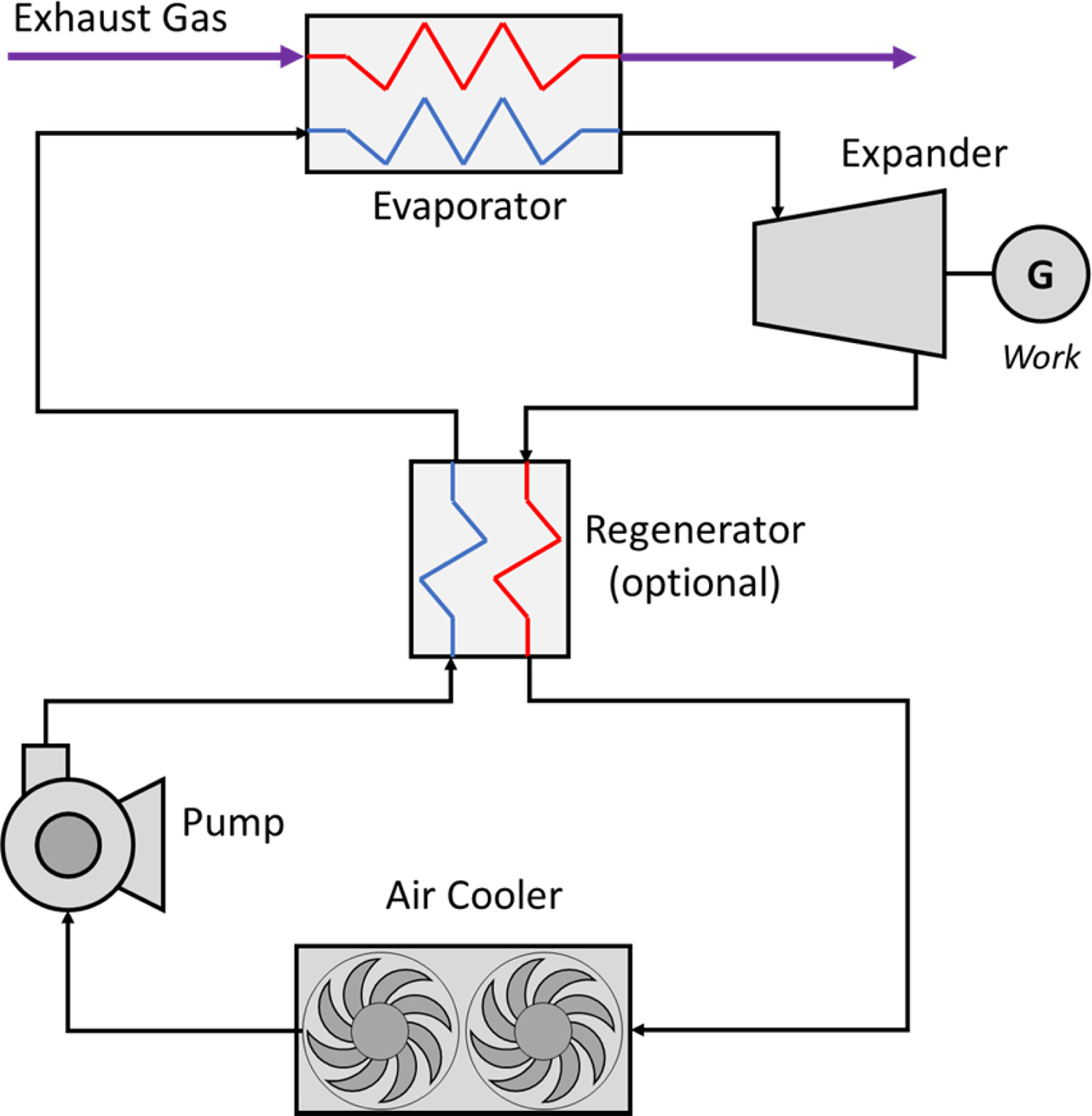
It is not logical to compare the performance of ORC using low-grade heat with electricity generation from conventional power plants using high-quality combustion heat. Hence, it is more reasonable to evaluate economic gain and technical feasibility of electricity generation from the ORC integrated with waste heat recovery, in conjunction with energy supply and consumption related to district heating systems. The schematic diagram for the ORC considered in this study is presented in Fig. 1. External heating source provides heat required for the evaporation of the working fluid in the evaporator, while a turbine is used to produce power. A condenser, typically, air cooler, is employed to reject heat from the exhaust stream from the expander and additional heat exchanger may be added to recover the heat from it.
The screening of working fluids available and its selection for the ORC is made by considering the temperature of external heating and cooling sources for the evaporator and the cooler, respectively, and the evaporator duty for the ORC. One of guidelines for the selection of working fluid can be found from Peris et al. [7], and R245fa is selected in this study.
Process modeling and simulation is carried out in an Aspen HYSYS® environment, in which Peng-Robinson method is selected for the evaluation of thermodynamic and physical properties. The work done by Rowshanaie et al. [14] and Ur-Rehman et al. [15] were referred to determine design conditions required for the simulation of the ORC. Key assumptions and input parameters related to process simulation are given as below:
- Efficiency for the expander: 75%
- Efficiency for the pump: 75%
- Minimum temperature approach for the heat exchange: 31 oC
- No pressure drop assumed for heating and cooling utility
- Pressure drop for ORC evaporator: 80 kPa
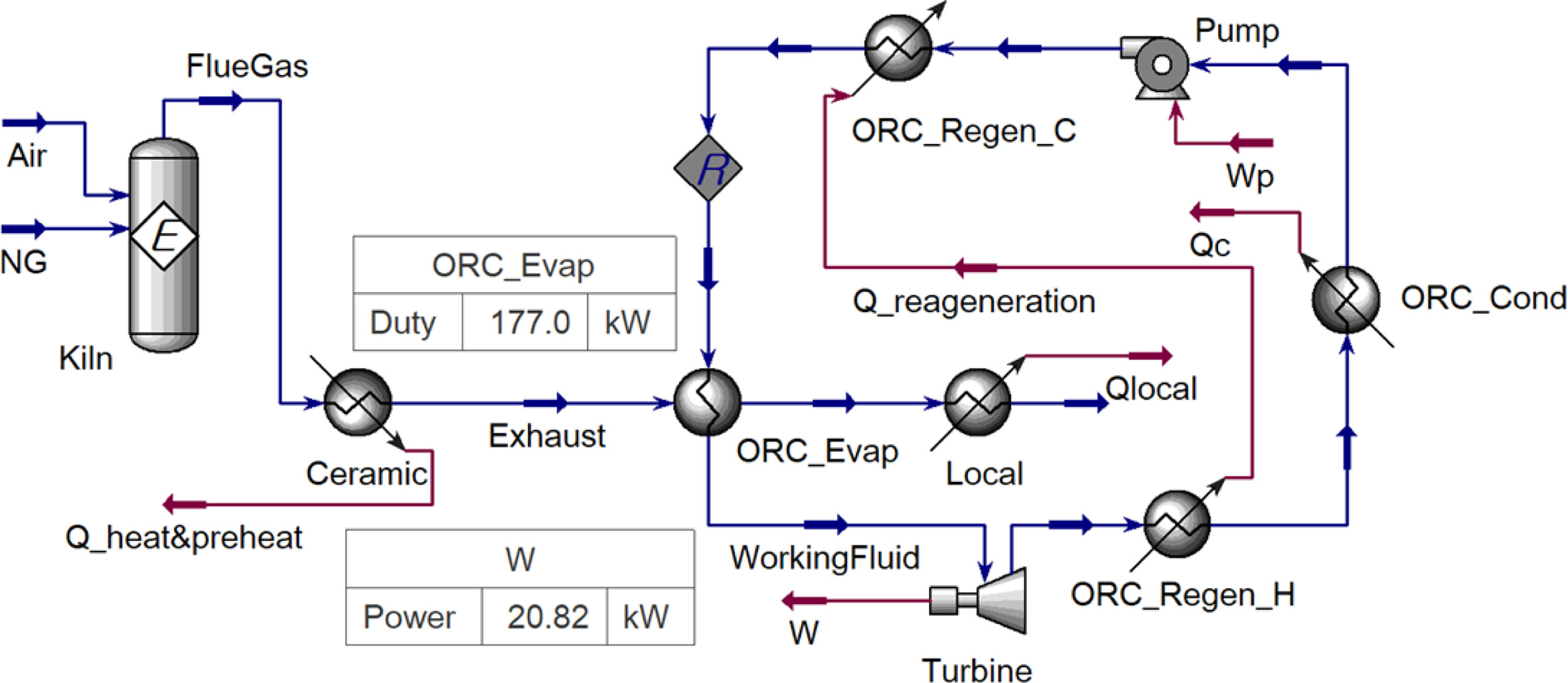
The process model built in the simulator is illustrated with Fig. 2. In order to embody the recovery of waste heat from the kiln exhaust in the simulation, the combustion is, first, modeled with an equilibrium reactor in which natural gas is burnt with air, based on the composition of natural gas feed and flue gas temperature given in Table 1 Data of exhaust flue gas from kilns
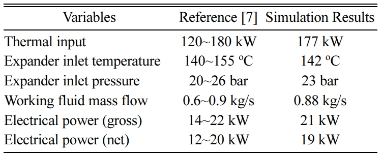
. The outlet temperature of exhaust flue gas and the outlet air temperature from ORC evaporator is assumed to 287 oC and 170 oC, the amount of heat utilized in the ORC is 177 kW, based on the Peris et al. [7]. The process modeling of the ORC, subject to the waste heat recovery of exhaust flue gas from the kiln, is validated with the reference [7], which shows a fairly good agreement as shown in Table 2.
Meanwhile, waste heat recovered from exhaust gases is to be supplied to district heating through the accumulator, so the temperature of the accumulator must be selected enough to supply energy to the district heating. Also, care should be made to determine the level of tem- perature for the accumulator because of some potential issues or problems, related to reduction in heat storage efficiency and vaporization of storage media when the accumulator temperature is too high. In addition, it is important to carry out cost-effective and energy-efficient sizing of a heat accumulator subject to energy demand and supply. When the heat accumulator is too small, operability issue may be occurred because of sudden changes in temperature in the accumulator, while the system is not effective to deal with temperature variation with an over-sized accumulator.
|
Fig. 1 Schematic diagram for a simple ORC. |
|
Fig. 2 Process simulation for the ORC. |
For the case study considered, the waste heat of the exhaust gas is recovered from the ORC in the tem- perature range of 287 oC and 170 oC, with which 177 kW of heat is recovered. Since in the district heating systems water temperature is raised from 55 oC to 95 oC, it is assumed that additional heat is recovered until the exhaust gas are heat exchanged down to 100 oC, with which 104 kW of additional heat can be utilized.
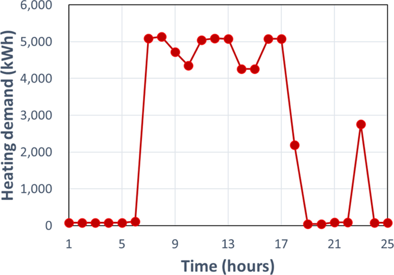
Energy demand for district heating systems can be characterized with changes in daily demand and annual demand. In this study, daily demand selected for the modeling and analysis in this work is based on the demand for industrial buildings in winter when heating is required, and the typical profile of changes in energy demand over time is shown in Fig. 3 [16].
However, Fig. 3 shows the typical heating demand in the winter, so the profile of changes in heat demand in an annual basis should be further defined. The annual profile for the heat demand is generated from the application of the heat pattern analysis study [12], of which results are given in Fig. 4.
It is assumed that the operation time of the ceramic factory to meet the annual demand would be 8,040 hours. As shown in Fig. 3, most of heating in the building is required during office hours, while there is virtually no heating demand for non-office hours. Hence, heat storage facilities should be introduced for the utilization of waste heat from the ceramic plant, as the ceramic plant is virtually operated at steady-state mode throughout the whole year. The heat storage facility considered in this study is assumed to be a short-term heat accumulator using water, which has 90%, 95% and 99% per hour of heat insulation efficiency [10].
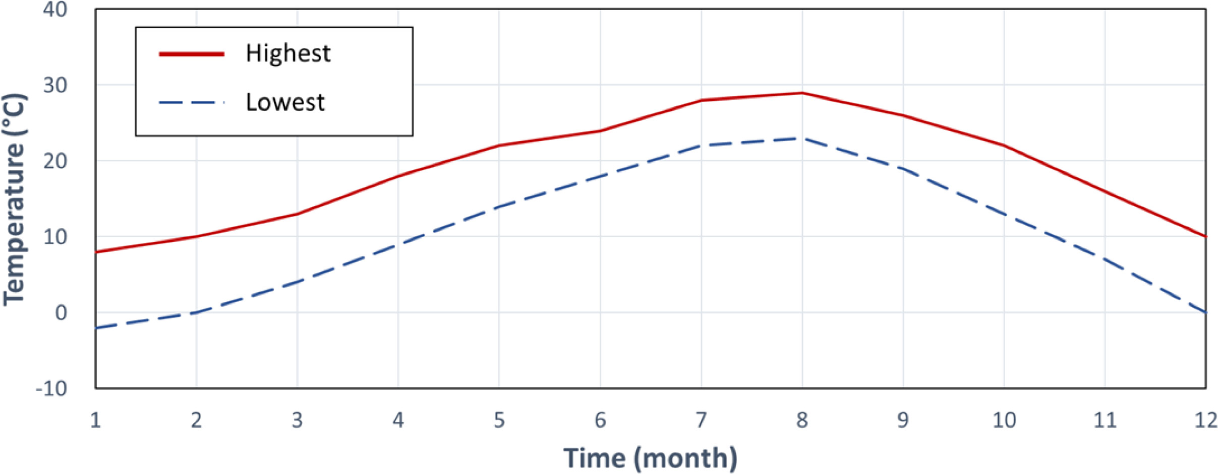
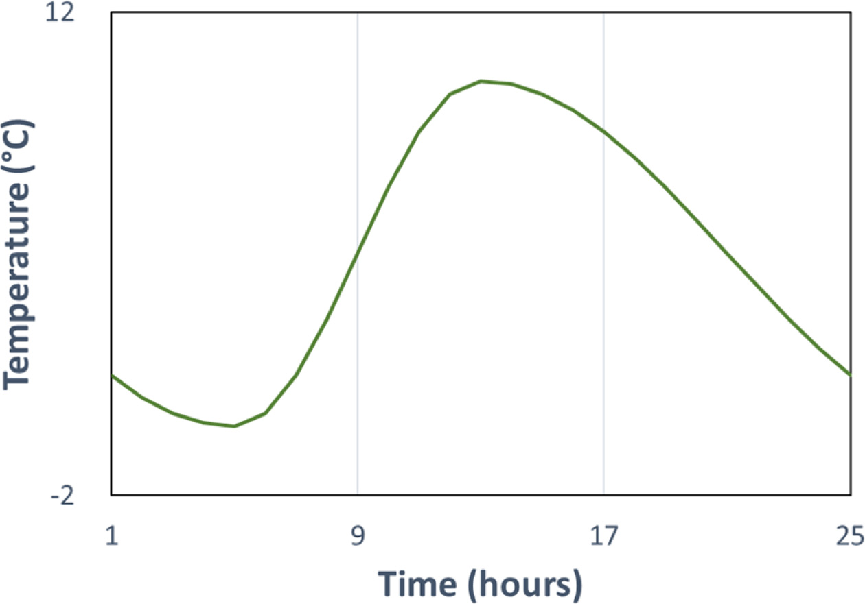
The location of a district heating system and a ceramic plant is assumed to be at Busan, Republic of Korea. The amount of heat stored in the heat accumulator is based on the temperature increased, compared to the air temperature. The heating supply and recovery tempera- tures are set to be 95 oC and 55 oC according to the data of the Korea District Heating & Cooling Association [17]. For the analysis of annual demand, the average maximum and lowest temperature over the year [18] are taken, as shown in Fig. 5, while the average value between the highest and lowest temperature in December is taken for the analysis of daily demand. The maximum and minimum temperatures to be measured are 14:00 p.m. and 05:00 a.m., respectively, and the temperature change between these two time periods is assumed to follow a sine wave (Fig. 6).
For the analysis with the profile of annual demand, the initial state of the heat accumulator is assumed to be operated at the same temperature as the ambient temperature, and a certain degree of heat accumulated in the beginning is also considered. When analyzing for the daily demand, the initial and final temperature of the heat accumulator are set to be the same, assuming a daily cycle.
An economic evaluation related to the integration of a district heat system with industrial waste heat recovery is made with two integration options: The first case for the integration (referred as Case 1) is that industrial waste heat available from the exhaust gas is, in advance, utilized in the ORC and then the remaining waste heat is utilized for district heating. The second case, referred as Case 2, is that all the waste heat available is only used for district heating without being used in the ORC. As explained above, three levels of insulation efficiency for the accumulator, namely, 90%, 95% and 99%, and two profiles of heat demand, namely, daily demand, D, and annual demand, A, are considered. In order to name different cases considered in this work, two suffixes are added for Case 1 and 2 with D or A, which is then followed by the number showing the levels of insulation efficiency. For example, Case 1D90 is the case based on the profile of daily heat demand, which utilizes both ORC and district heating for the heat recovery, subject to 90% of insulation efficiency for the accumulator.
Since the recovered energy is transformed to different types of energy, namely, electricity generated from the ORC and heating source for the district heating, benefits from integrated should be quantified in terms of profits against expenses for cases considered. For economic evaluation, purchase prices, not sale prices, of electricity and district heating, are applied because these benefits are obtained as a result of energy saving. These prices can be obtained from Korea Gas Corporation and Korea Electric Power Corporation, which are major energy suppliers in Republic of Korea.
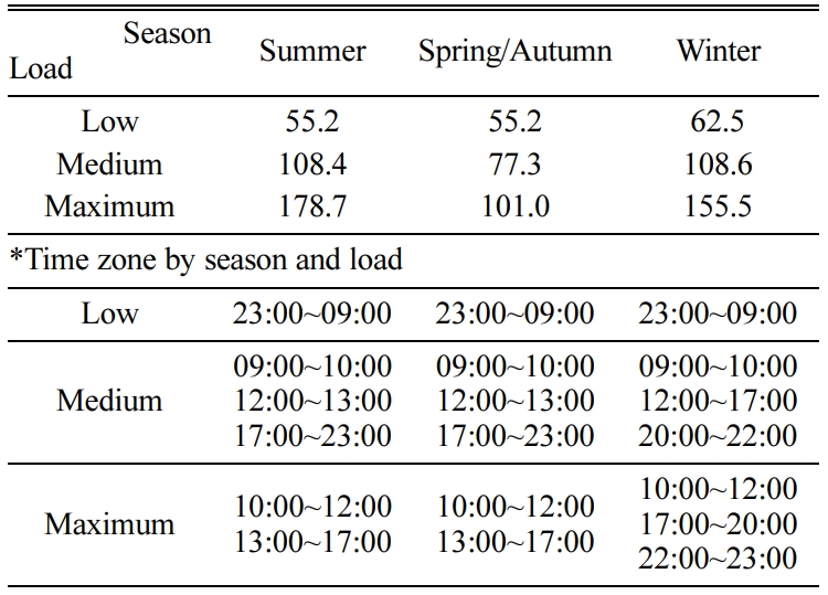
When natural gas is used for the district heating of buildings, tariffs for business-purpose city gas is region specific. 18.0 won/MJ is used in our work, which is the charge rate of city gas for business heating in Busan in 2019 [19]. The electricity prices for industrial high-voltage supply are provided in Table 3 [20] in details, which are varied with time of the day and season.
Case 1: Integration of waste heat for the use of both ORC and district heating
Table 4 shows the results of cases in which both ORC and district heating are integrated with industrial waste heat, subject to daily change in heat demand. As the insulation efficiency of the heat storage increases, the amount of recovered heat from the accumulator increases, which results in reduction in energy loss related to heat recovery in the district heating and, consequently, savings in overall cost.
Table 5 shows the results of cases in which both ORC and district heating are integrated with industrial waste heat, subject to annual changes in heat demand. The overall trend is the same with Cases 1Ds, as observed in Table 4. For both Cases 1Ds and Cases 1As, the higher the insulation efficiency of the accumulator, the more energy utilized through the accumulator. This characteristic is more evident in Cases 1Ds of daily demand than Cases 1As of annual demand. This phenomenon is also observed for the size of the accumulator, as the bigger volume of accumulators, the higher insulation efficiency. Additionally, the sizes of the heat accumulators for Cases 1As are bigger than that of Cases 1Ds. This difference is contributed by variations in seasonal heat demand and the dependence of heat storage efficiency on ambient temperature.
Case 2: Integration of waste heat for the use of district heating only
Overall results of Cases 2Ds, subject to changes in daily heat demand, are provided in Table 6 when waste heat is only recovered in the district heating systems, not in the ORC. Compared to Cases 1Ds, an additional waste heat recovery of in the range of 2,500 to 3,500 kW is possible for district heating, resulting in 1.59 to 1.89 times of additional cost savings, although the energy efficiency of the heat accumulator is similar.
Similar to the Case 1As, waste heat recovery in overall for Case 2As increases when the insulation efficiency of the accumulator increases, as observed in Table 7. Cases 2As, based on annual changes in heat demand without using the ORC, can save up to 1.86 times more than Cases 1As using the ORC. From Cases 1Ds and 2Ds, the use of ORC does not have meaningful impact on the degree of energy utilization through the accumulator.
The summary of results for the case study presented in above is shown in Table 8. This overall result clearly shows that the use of industrial waste heat to local district heating is more cost-effective than generating power through the ORC based on the industrial waste heat. Nevertheless, there are a few practical issues to be assessed for the industrial waste heat, which may not be quantified or interpreted from the viewpoint of economic benefit. One of major issues is as the provision of electricity through grid is more straightforward and relatively easy than the supply of heat through pipes. Another issue to be taken into account is that here is considerable heat loss in the piping during the trans- portation of working fluid for heat recovery. Hence, additional expenditure for the insulation of piping should also be considered, although this point has not been fully discussed in this study. With recent advances made for the technologies of heat storage and its transportation, it is expected that energy supply through district heating networks would be very competitive in near future.
|
Fig. 3 Daily demand for heat from industrial buildings in winter |

|
Fig. 4 An annual profile of heat demand predicted for industrial buildings. |
|
Fig. 5 Typical profiles of the highest and lowest average temperature over a year. |
|
Fig. 6 Profile assumed for temperature changes over a day. |
|
Table 4 Results of Cases 1D |

*This is the ratio in percentage between energy utilized from and energy recovered to an accumulator |
In this study, waste heat recovery with the integration of ORC and district heating systems is considered to enhance the energy efficiency of ceramic industry. From the case study, it is more effective to recover waste heat only for district heating systems, rather than to generate electricity with the ORC before being used in district heating systems. However, industry prefers to use the ORC for the waste heat recovery, due to the convenience of electricity supply and the additional cost related to the installation of piping for over-the-fence heat recovery. It is expected that the competitiveness of waste heat recovery systems using district heating will be improved, along with the development in the area of heat storage and transportation infrastructure.
Further studies will be carried out to evaluate econo- mics related to heat transport and its storage in more details, including energy losses in the transportation of energy and any additional costs related to the integration between industrial plant and district heat systems. Also, systematic design method should be further exploited to determine the most appropriate design of heat recovery and storage systems.
This work is a research conducted with the support of the Korea Institute of Energy Technology Evaluation and Planning with the government (Ministry of Trade, Industry and Energy) in 2019 (20192010106970, De- velopment of the integrated and decentralized smart hub thermal storage system for heat trading)
- 1. R. Rakshit and A.K. Das, Precision Engineering 59 (2019) 90-109.
-

- 2. H. Jouhara, N. Khordehgah, S. Almahmoud, B. Delpech, .A Chauhan, and S.A. Tassou, Therm. Sci. Eng. Prog. 6 (2018) 268-289.
-

- 3. B. Delpech, B. Axcell, and H. Jouhara, E3S Web of Conf. 22 (2017) 00034.
-

- 4. M. Milani, L. Montorsi, M. Stefani, and M. Venturelli, E3S Web of Conf. 22 (2017) 00117.
-

- 5. A. Mezquita, J. Boix, E. Monfort, and G. Mallol, App. Therm. Eng. 65[1-2] (2014) 102-110.
-

- 6. S. Quoilin, M.V.D. Broek, S. Declaye, P. Dewallef, and V. Lemort, Renewable and Sustainable Energy Rev. 22 (2013) 168-186.
-

- 7. B. Peris, J. Navarro-Esbrí, F. Mole's, and A. Mota-Babiloni, Energy 85 (2015) 534-542.
-

- 8. C. Agrafiotis and T. Tsoutsos, App. Therm. Eng. 21[12] (2001) 1231-1249.
-

- 9. S.-Y. Oh, M. Binns, Y.-K. Yeo, and J.-K. Kim, App. Energy 131 (2014) 26-39.
-

- 10. H. Gadd and S. Werner, App. Energy 108 (2013) 176-183.
-

- 11. L. Miró, J. Gasia, and L.F. Cabeza, App. Energy 179 (2016) 284-301.
-

- 12. A. Steiner, K.K. Yumkella, J. Clos, and G.V. Begin, U.N. Environ. Programme, Denmark, 2014.
-

- 13. J. Navarro-Esbrí, B. Peris, R. Collado, and F. Molés, PE&PQJ, 1[11] (2013), 624-629.
-

- 14. O. Rowshanaie, S. Mustapha, K.A. Ahmad, and H. Rowshanaie, J. Teknol. 77[27] (2015) 9-18.
-

- 15. M. Ur-Rehman, M.S. Khurram, S. Rafiq, S.A. Memon, M. Ghauri, F, Jamil, M.H. Jaffery, and M.G. Doggar, Bulg. Chem. Commun. 50[2] (2018) 254-264.
- 16. A. Hussain, V.-H. Bui, H.-M. Kim, Y.-H. Im, and J.-Y. Lee, Energies 10[6] (2017) 789.
-

- 17. Korea Dist. Heat. & Cool. Assoc. http://www.kdhca.co.kr/
- 18. Natl. Oceanic Atmos. Adm. https://www.ncdc.noaa.gov/
- 19. Korea Electr. Power Corp. http://home.kepco.co.kr/kepco/main.do
- 20. Korea Gas Corp. http://www.kogas.or.kr/portal/index.do
 This Article
-
2021; 22(1): 106-113
Published on Feb 28, 2021
- 10.36410/jcpr.2021.22.1.106
- Received on Nov 9, 2020
- Revised on Nov 17, 2020
- Accepted on Dec 4, 2020
 Services
- Abstract
introduction
process modeling of the orc and its validation
case study
conclusions and future work
- Acknowledgements
- References
- Full Text PDF
Shared
 Correspondence to
- Jin-Kuk Kim
-
Department of Chemical Engineering, Hanyang University, 222 Wangsimni-ro, Seongdong-gu, Seoul, 04763, Republic of Korea
Tel : +82-2-2220-2331 Fax: +82-2-2220-3119 - E-mail: jinkukkim@hanyang.ac.kr




 Copyright 2019 International Orgranization for Ceramic Processing. All rights reserved.