- Effect of Mo metal foil shielding on infrared transmission of spark plasma sintered ZnS ceramics
Wook Ki Jung, Ji-won Hong and Doo Hyun Choi*
Agency for Defense Development (ADD), Yuseong P.O. Box 35, Daejeon 34186, Republic of Korea
This article is an open access article distributed under the terms of the Creative Commons Attribution Non-Commercial License (http://creativecommons.org/licenses/by-nc/4.0) which permits unrestricted non-commercial use, distribution, and reproduction in any medium, provided the original work is properly cited.
Fabrication of infrared (IR) transparent ZnS ceramics by spark plasma sintering (SPS) suffers from carbon contamination due to the graphite mold in the SPS system. In the present work, we consolidated transparent ZnS ceramics by SPS using Mo metal foil to prevent the generation of carbonate and/or carbon impurities in the sintered product. The effect of Mo foil on carbon contamination and IR transmittance was investigated. The Fourier transform infrared spectroscopy (FTIR) results revealed that the C-O absorption peak was significantly reduced, however, sulfur vacancies were generated, thus, deteriorating the overall transmittance. The sulfur vacancies were eliminated by post-annealing the specimen in a nitrogen atmosphere, whereby the overall IR transmittance was partially recovered. The results indicate that metal foil wrapping of green bodies could be potentially applicable for the fabrication of carbon contamination-free ZnS ceramics via SPS system
Keywords: IR transparent ZnS ceramics, Spark plasma sintering, Mo metal foil, Carbon contamination, Sulfur vacancies, Post-annealing
Polycrystalline transparent ceramics are emerging candidates for IR windows and domes owing to their desirable mechanical strength, as well as IR transparency [1, 2]. Among them, transparent ZnS materials are con- sidered as one of suitable window materials for the long wavelength infrared band [3]. The wide bandgap of the ZnS makes it possible for the applications such as transparent conductors and light-emitting sensors [4-6].
Various techniques for fabricating IR transparent ZnS ceramics have been reported, including chemical vapor deposition (CVD), hot pressing (HP), and hot-isostatic pressing (HIP). Among these processing techniques, CVD is the most traditionally used method to fabricate IR transparent ZnS ceramics. The transparent ZnS ceramics fabricated by CVD and further densified by HIP process exhibit the best optical properties, but poor mechanical behavior due to an enlarged grain micro- structure. To enhance the mechanical properties of ZnS, sintering techniques such as hot-press (HP) or spark plasma sintering (SPS) can be used to reduce the grain size and obtain a fine-grained microstructure [7-10].
Special sintering techniques such as HP and SPS allow nearly full densification of the ceramics by suppressing abnormal grain growth. The SPS system, which involves the use of electrical energy and mechanical pressure, sinters the ceramics within a few minutes, and can consolidate many transparent ceramics at a faster rate than HP or pressureless sintering. The spark plasma sintered ceramics exhibit gray/black discoloration, which has been reported in oxide systems such as Mg spinel, Al2O3, and Y2O3 [11-15]. The discoloration is caused by carbon contamination and/or oxygen vacancies, thus, deteriorating the optical transmittance [12]. While the oxygen vacancies are known to be induced by a carbothermal reduction reaction in the vacuum atmosphere and gaseous carbon, the carbon contamination is from the graphite mold used in the SPS system [16-19].
Several studies have been carried out to improve the discoloration in spark plasma sintered ceramics. In oxide systems, post-annealing procedure of the spark plasma sintered ceramic in air at high temperature replenishes the oxygen vacancies and eliminates carbon impurities, thus, improving the discoloration [15, 16, 20-22]. However, the post-annealed specimen exhibits inferior transmittance due to microstructural pore generation during heat treatment. The use of a metal foil to shield the green bodies in HP or SPS systems effectively suppresses carbon contamination, as well as oxygen vacancies [23, 24]. One recent study has investigated the use of Mo metal foil in a non-oxide system to suppress carbon contamination in spark plasma sintered CaF2 transparent ceramics [25]. Mo metal foil is one of the preferred novel metals such as Pt and Ta, and it is a metal with low reactivity as well as cost-effectiveness. The green body, wrapped with Mo foil, was successfully separated from the graphite mold, and the resultant transparent CaF2 ceramics exhibited increased transmittance.
While a few studies have been carried out on the fabrication of ZnS ceramics by SPS to obtain fine-grained IR windows [26-28], some of the as-prepared ZnS ceramics showed an absorption peak of CO2 at 4.2 µm in the transmission spectra despite the high purity of the as-prepared powder [28-30]. These carbonate-related absorption peaks could be related to carbon contamination from the graphite mold during the SPS process at high temperatures. There have been reports on metal foil shielding of ZnS in the HIP process, however, there is no report for metal foil shielding of ZnS in the SPS process [31, 32].
In this study, we fabricated IR transparent ZnS ceramics using SPS with Mo foil shielding. The aim of this study was to understand the effect of Mo foil on the IR transmittance of spark plasma sintered ZnS ceramics, and to prevent the carbon contamination. The Mo foil effectively protected the as-sintered specimen from carbonate-based impurities from the graphite mold, however, sulfur vacancies were generated in the as-sintered specimen. The overall IR transmittance was degraded and the sample exhibited a blackish color. The IR transmittance was restored by post-annealing in a nitrogen atmosphere.
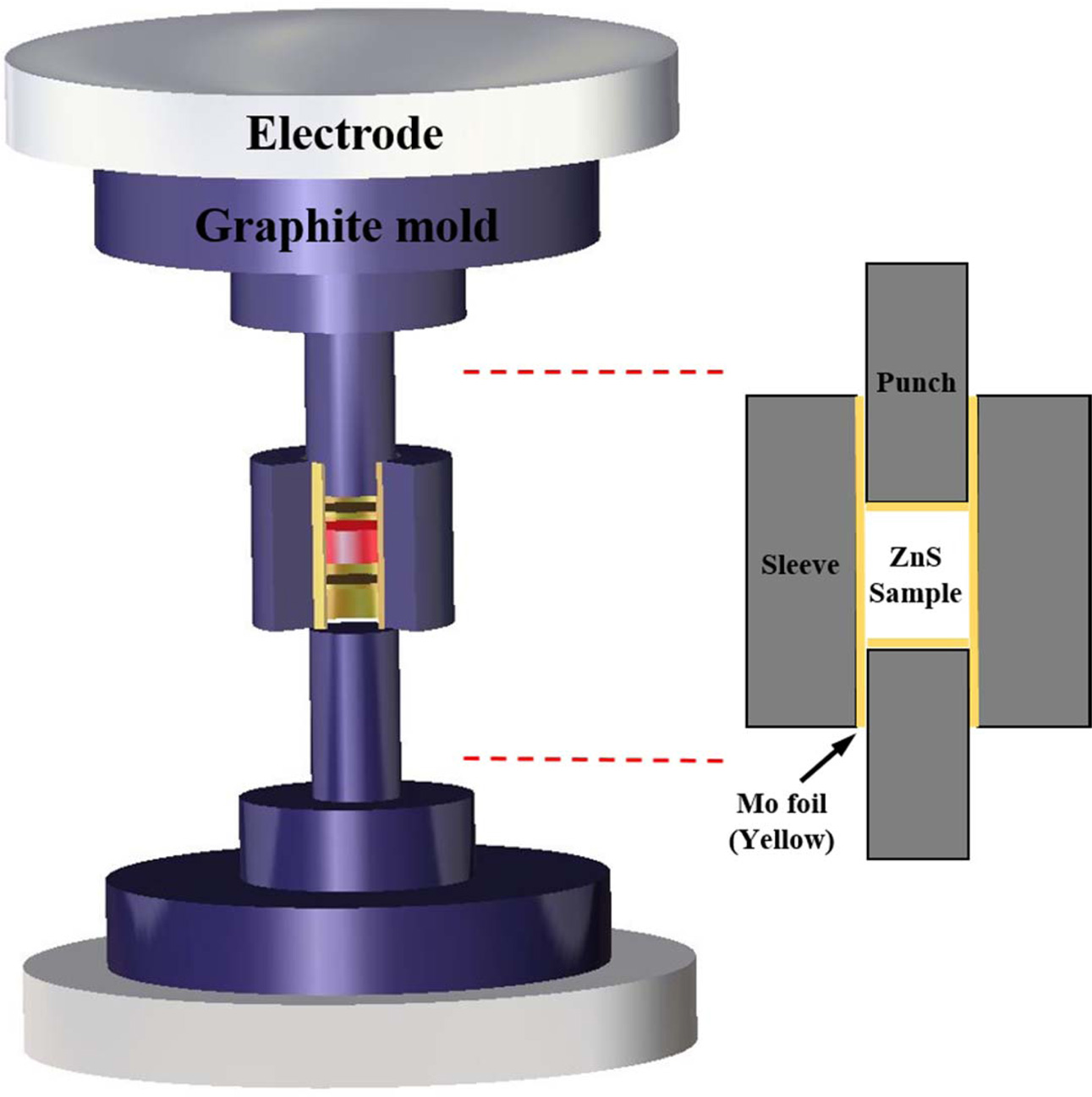
High-purity commercial ZnS powder (LTS, 99.99%) was used as the starting material. The experimental setup of the SPS process is schematically represented in Fig. 1. The powder was sieved through a 200-mesh screen, and then uniaxially dry-pressed into pellets at 20 MPa, and further cold-isostatically pressed (CIP) at 200 MPa. The green body (diameter of 12 mm and 50% of relative density) was poured into a graphite die (inner diameter of 12 mm). The green body and the graphite die were separated by Mo foil (0.025 mm in thickness) so that the CIPed ZnS ceramic was well wrapped inside. An optical pyrometer was used to measure the outside temperature by focusing on the hole in the graphite die. The graphite die was placed in the SPS operating chamber under a vacuum of approximately 10-3 torr. The obtained green bodies were heated to 600 oC at a heating rate of 100 oC/min, and further heated to 850 oC at a heating rate of 10 oC/min. An initial uniaxial pressure of 20 MPa was applied from room temperature to 600 oC, and was increased to 60 MPa at 600 oC and maintained during the heating and dwelling process. After dwelling at 850 oC for 10 mins, the pressure was released, and the specimen was allowed to cool at an uncontrolled rate. For comparison, ZnS ceramic without the presence of Mo foil was also fabricated. The specimen was consolidated using the same sintering condition, however, both ends of the graphite punch and the inner surface of the graphite die were coated with boron nitride as a releasing agent to facilitate the easy separation of sintered products. To investigate the effect of the post-annealing procedure on the spark plasma sintered sample with Mo foil shielding, the samples were annealed at 850 oC for 3 h under a nitrogen atmosphere. The resultant.
Infrared transmission spectra of the spark plasma sintered ZnS ceramics were measured using Fourier transform infrared spectroscopy (FTIR, Frontier, Perkin Elmer, USA) over a wavelength range of 2-14 µm. The formation of sulfur defects in the specimen was verified by electron spin resonance (ESR, JES-FA200, JEOL, Japan) with a fixed microwave power of 9 mW at 9.86 GHz. The microstructure of the fracture surface of the sintered specimens was examined by scanning electron microscopy (FE-SEM, Quanta 650, FEI, Netherlands). The thickness of the specimens was fixed at 1 mm.

|
Fig. 1 Schematic of the spark plasma sintering (SPS) arrangement with Mo foil shielding of the ZnS green body |
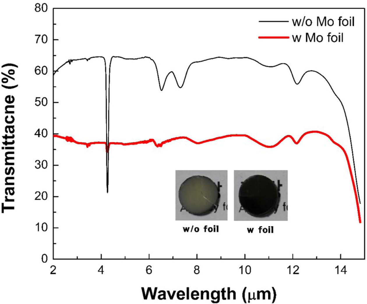
Fig. 2 shows the IR transmittance spectra and photo- graphs of spark plasma sintered ZnS ceramics with and without Mo foil shielding, obtained by FTIR measure- ment over a wavelength range of 2-14 µm. The inset shows photographs of the as-sintered ceramics. The ZnS ceramic fabricated without Mo foil shielding exhibits high transmittance in the IR region with a maximum transmittance of 63% at 8 µm except for a few absorption peaks. The strong absorption peak at 4.2 µm is attributed to CO2 absorption, and the peaks at 6.5 µm and 7.3 µm corresponds C-H absorption [28, 29, 33-35]. These carbon-related absorption features are due to carbon contamination induced by the graphite mold. In contrast, the ZnS ceramic shielded by Mo foil has lower absorption peaks compared to the ZnS ceramics fabricated without Mo foil shielding. This is due to the foil shielding, which successfully suppressed carbon contamination from the mold at high temperatures [25].
However, the Mo foil shielded ZnS ceramic displays lower IR transmittance in the overall IR wavelength region with a maximum transmittance of 37% at 8 µm. The overall transmittance decay has been widely observed in the other transparent oxide systems [13, 15, 20]. It is known that the transparent ceramics with blackish color and the decrease in transmittance is mainly caused by the generation of oxygen vacancies when sintering proceeds in reducing condition such as SPS and vacuum sintering. The previous investigation showed that the generation of oxygen vacancies narrowed the transition energy levels with a band gap which deteriorated the transmittance for the infrared range and the visible range [14]. The oxygen vacancies could be removed, and the specimen became transparent after post-annealing in the air to replenish the oxygen.
A similar phenomenon has been also reported for ZnS ceramics fabricated by HP and further densified by HIP [36]. The previous study indicated that a decrease in transmittance across the IR spectral range in ZnS ceramics is caused by an increase in sulfur vacancies. The presence of defects in ZnS ceramics narrows the bandgap, which increases the influence of the absorption edge of the imaginary part (ε2(ω)) in the dielectric function. The refractive index (n(ω)) is calculated using the complex dielectric function [37] according to,

where ε1 and ε2 are the real and imaginary parts of the dielectric function, respectively.
Defect-containing ZnS has a slightly higher refractive index according to equation (1). This situation increases the theoretical reflectivity at the air/ZnS interface. The theoretical transmittance decay also occurs, as shown in equations (2) and (3) [38].

Accordingly, the blackish color of the Mo foil shielded ZnS specimen could be due to the generation of sulfur vacancies during the SPS process.
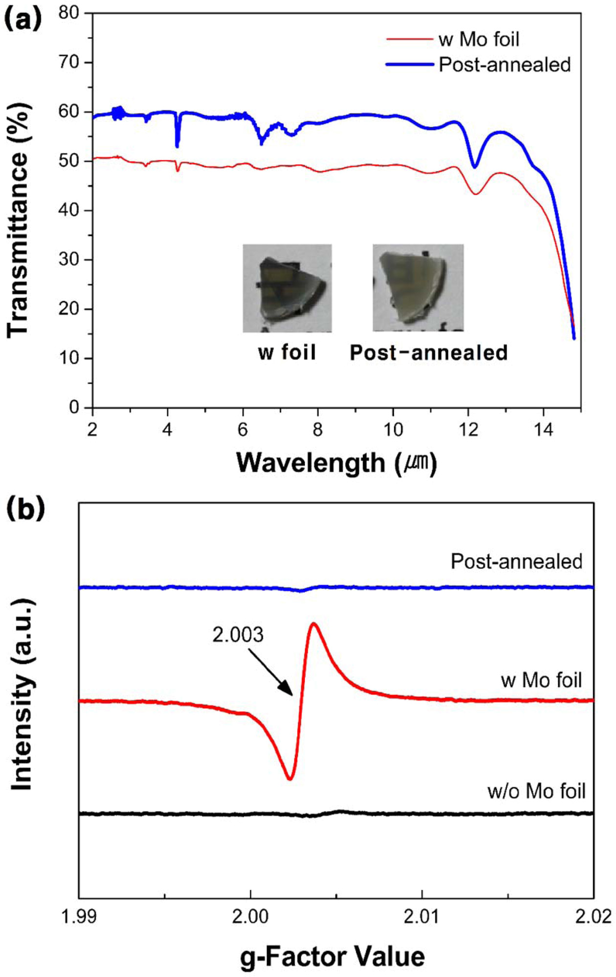
Fig. 3(a) shows the transmittance value of the post-annealed specimen compared to that of the Mo foil shielded ZnS ceramic. The inset shows the corresponding photographs of the Mo foil shielded and post-annealed ZnS specimen. The IR transmittance of the post-annealed ZnS specimen increased by 10%, and the specimen turned yellowish after the post-annealing procedure, compared to that of the Mo shielded ZnS specimen. Many studies have reported that annealing ZnS in a nitrogen atmosphere above 500 oC enhances the crystallinity of ZnS, and recovers the stoichiometry [39-41]. Therefore, the improved IR transmittance of the post-annealed ZnS ceramics is expected to be due to the reduction of sulfur vacancies. For many transparent ceramics manu- factured by conventional SPS process, carbon-related light absorption has been reported [42-44]. In this work, the transparent ZnS ceramics fabricated by SPS with Mo foil shielding, and following post-annealing shows high IR transmittance (60% @ 8 µm) while effectively blocking the carbon contamination.
In proof of existence of sulfur vacancies in the spark plasma sintered ZnS ceramics, the ESR spectra was analyzed for the specimens. The ESR analysis has been reported to detect the anion vacancies in oxide and sulfide systems [14, 20, 45]. As mentioned before, the anion vacancies are known to form at high temperatures under reduction atmosphere. These vacancy defects generate unpaired electron, and ESR can detect the signal from the samples. Fig. 3(b) shows the ESR spectra of the as-sintered ZnS ceramics with and without Mo foil wrapping and that of the post-annealed Mo foil shielded ZnS ceramic to determine the existence of sulfur vacancies. An intense signal corresponding to a g-factor of 2.003 is only observed in the Mo foil shielded ZnS ceramic [45, 46]. This indicates the presence of sulfur vacancies, and is correlated with the overall IR transmittance decay. Zinc sulfide decomposes during the high-temperature sintering process with evaporating sulfur, and this accelerates at higher temperature [47, 48]. During SPS, Mo foil shielding enhances the contact area between the ZnS sample and the graphite mold and/or punch, thus, increasing the current flow. The increased current flow to the ZnS specimen increases the actual temperature above the value measured by the optical pyrometer [49-51]. The Mo foil shielding increases temperature of the ZnS specimen, thus, resulting in a higher sulfur vacancy generation.
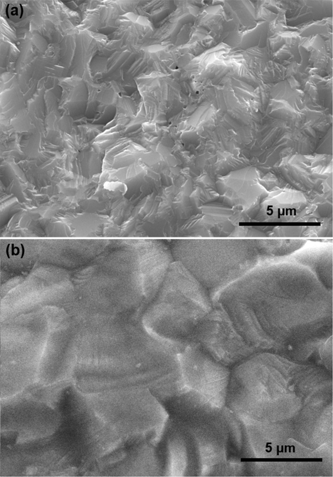
Fig. 4 shows the fracture surface of the spark plasma sintered ZnS ceramics. As shown in Fig. 4(a), the microstructure of ZnS fabricated without Mo foil shows residual pores of several hundred nanometers. It is considered that the sintering conditions such as temperature and pressure was insufficient for the complete densification of ZnS ceramics. On the other hands, the Fig. 4(b) exhibits that the Mo foil shielded ZnS ceramic is seen to have a larger grain size and pore-free microstructural features compared with that of the unshielded sample. It is common sintering experience that grain growth behavior is dominant in the final-stage sintering [52]. In this regards, further grain growth and elimination of residual pores suggest that the Mo foil shielded ZnS ceramic experienced higher temperatures during spark plasma sintering.

|
Fig. 2 IR transmittance spectra of the as-sintered ZnS ceramics (thickness: 1 mm) without and with Mo foil wrapping under 60 MPa and their corresponding photographs (inset). |

|
Fig. 3 (a) IR transmittance spectra of as-sintered and postannealed ZnS ceramics (thickness: 1 mm) spark plasma sintered with Mo foil wrapping and their corresponding photographs (inset). (b) ESR spectra of the as-sintered ZnS ceramics without (black line) and with (red line) Mo foil wrapping and postannealed ZnS ceramic spark plasma sintered with Mo foil (blue line). |

|
Fig. 4 SEM micrographs showing fractured surface of the ZnS ceramics spark plasma sintered (a) without Mo foil and (b) with Mo foil. |
In this work, the effect of Mo foil on the IR transmittance of spark plasma sintered ZnS ceramics was investigated. The Mo metal foil wrapping of the green body remarkably prevented the as-sintered ZnS ceramics from carbon-related contamination. Moreover, it exhibited a discoloration phenomenon and microstructural grain growth. It was accessed that the Mo metal foil shielding on ZnS generated sulfur vacancies during SPS process, resulting in transmittance decay in the overall IR range (2–14 µm). Post-annealing in a nitrogen atmosphere enabled the reduction of sulfur vacancies improving the IR transmittance. The Mo metal foil shielding on green body for SPS is potentially powerful reference to make IR transparent ZnS ceramics without carbon contamination.
This work was supported by the Defense Acquisition Program Administration (DAPA) and Agency for Defense Development (ADD).
- 1. D.C. Harris, in Proceedings of Infrared Technology XXI, September 1995 (SPIE 2552) p. 325.
-

- 2. E. Yashina, Inorg. Mater. 39[7] (2003) 663-668.
-

- 3. J. McCloy, in Proceedings of Window and Dome Technologies and Materials X, May 2007, (SPIE 6545).
-

- 4. N. Mahuli, D. Saha, S.K. Maurya, S. Sinha, N. Patra, B. Kavaipatti, and S.K. Sarkar, J. Phys. Chem. C 122[28] (2018) 16356-16367.
-

- 5. P. D’Amico, A. Calzolari, A. Ruini, and A. Catellani, Scientific Reports 7 (2017) 16805.
-

- 6. P. Jiang, J. Jie, Y. Yu, Z. Wang, C. Xie, X. Zhang, C. Wu, L. Wang, Z. Zhu, and L. Luo, J. Mater. Chem. 22[14] (2012) 6856.
-

- 7. C.S. Chang, J.L. He, and Z.P. Lin, Wear 255[1] (2003) 115-120.
-

- 8. P. Ramavath, V. Mahender, U.S. Hareesh, R. Johnson, S. Kumari, and N. Eswara Prasad, Mater. Sci. Eng. A 528[15] (2011) 5030-5035.
-

- 9. D. Townsend and J.E. Field, J. Mater. Sci. 25[2] (1990) 1347-1352.
-

- 10. G.R. Durand, N. Hakmeh, V. Dorcet, V. Demange, F. Chevire, and O. Merdrignac-Conanec, J. Eur. Ceram. Soc. 39[10] (2019) 3094-3102.
-

- 11. M. Prakasam, D. Michau, O. Viraphong, and A. Largeteau, Adv. Appl. Ceram. 115[6] (2016) 333-341.
-

- 12. K. Morita, B.-N. Kim, H. Yoshida, K. Hiraga, and Y. Sakka, Acta Mater. 84 (2015) 9-19.
-

- 13. R.S. Razavi, M. Ahsanzadeh-Vadeqani, M. Barekat, M. Naderi, S.H. Hashemi, and A.K. Mishra, Ceram. Int. 42[6] (2016) 7819-7823.
-

- 14. X. Li, X. Mao, M. Feng, J. Xie, B. Jiang, and L. Zhang, J. Eur. Ceram. Soc. 36[16] (2016) 4181-4184.
-

- 15. W.K. Jung, H.J. Ma, Y. Park, and D.K. Kim, Scrip. Mater. 137 (2017) 1-4.
-

- 16. K. Morita, B.-N. Kim, H. Yoshida, K. Hiraga, and Y. Sakka, J. Am. Ceram. Soc. 98[2] (2015) 378-385.
-

- 17. K. Morita, B.-N. Kim, H. Yoshida, K. Hiraga, and Y. Sakka, J. Eur. Ceram. Soc. 36[12] (2016) 2961-2968.
-

- 18. G. Bernard-Granger, N. Benameur, C. Guizard, and M. Nygren, Scr. Mater. 60[3] (2009) 164-167.
-

- 19. D.T. Jiang, D.M. Hulbert, U. Anselmi-Tamburini, T. Ng, D. Land, and A.K. Mukherjee, J. Am. Ceram. Soc. 91[1] (2008) 151-154.
-

- 20. W. Zhang, T. Lu, N. Wei, B. Ma, F. Li, Z. Lu, and J. Qi, Opt. Mater. 34[4] (2012) 685-690.
-

- 21. L. An, A. Ito, and T. Goto, J. Am. Ceram. Soc. 94[11] (2011) 3851-3855.
-

- 22. I. Reimanis and H.J. Kleebe, J. Am. Ceram. Soc. 92[7] (2009) 1472-1480.
-

- 23. L. Gan, Y.-J. Park, M.-J. Park, H. Kim, J.-M. Kim, J.-W. Ko, and J.-W. Lee, J. Am. Ceram. Soc. 98[7] (2015) 2002-2004.
-

- 24. L. Gan, Y.-J. Park, L.-L. Zhu, S.-I. Go, H. Kim, J.-M. Kim, and J.-W. Ko, Ceram. Int. 42[12] (2016) 13952-13959.
-

- 25. P. Wang, M. Yang, S. Zhang, R. Tu, T. Goto, and L. Zhang, J. Eur. Ceram. Soc. 37[13] (2017) 4103-4107.
-

- 26. Y. Chen, L. Zhang, J. Zhang, P. Liu, T. Zhou, H. Zhang, D. Gong, D. Tang, and D. Shen, Opt. Mater. 50 (2015) 36-39.
-

- 27. C. Chlique, G. Delaizir, O. Merdrignac-Conanec, C. Roucau, M. Dolle, P. Rozier, V. Bouquet, and X.H. Zhang, Opt. Mater. 33[5] (2011) 706-712.
-

- 28. J. Hong, W.K. Jung, and D.H. Choi, Ceram. Int. 46[10] (2020) 16285-16290.
-

- 29. Y. Chen, L. Zhang, J. Zhang, P. Liu, T. Zhou, H. Zhang, D. Gong, D. Tang, and D. Shen, Opt. Mater. 50 (2015) 36-39.
-

- 30. C. Chlique, O. Merdrignac-Conanec, N. Hakmeh, X. Zhang, and J.-L. Adam, J. Am. Ceram. Soc. 96[10] (2013) 3070-3074.
-

- 31. J. McCloy and R. Korenstein, in Proceedings of Window and Dome Technologies and Materials XI, April 2009 (SPIE 7302) p. 1.
-

- 32. J.S. McCloy, R. Korenstein, and B. Zelinski, J. Am. Ceram. Soc. 92[8] (2009) 1725-1731.
-

- 33. K.T. Lee, B.H. Choi, J.U. Woo, J.S. Kang, J.H. Paik, B.U. Chu, and S. Nahm, J. Eur. Ceram. Soc. 38[12] (2018) 4237-4244.
-

- 34. M. Wlodarski, M. Putkonen, and M. Norek, Coatings 10[5] (2020) 459-471.
-

- 35. F. Rahmawati, F.R. Putri, and A. Masykur, Open Chem. 17[1] (2019) 132-141.
-

- 36. M. Liu, S. Wang, C. Wang, G. Zhang, Y. Wang, X. Li, P. Shang, R. Zhang, Y. Ji, and J. Chu, Comput. Mater. Sci. 174 (2020) 109492-109499.
-

- 37. F.L. Tang, Z.X. Zhu, H.T. Xue, W.J. Lu, Y.D. Feng, and Z.M. Wang, Physica B 407[24] (2012) 4814-4818.
-

- 38. R. Apetz and M.P.B. van Bruggen, J. Am. Ceram. Soc. 86[3] (2003) 480-486.
-

- 39. F. Goto, K. Shirai, and M. Ichimura, Sol. Energy Mater Sol. Cells 50[1] (1998) 147-153.
-

- 40. F. Zakerian and H. Kafashan, Superlattices Microstruct. 124 (2018) 92-106.
-

- 41. S.W. Shin, S.R. Kang, J.H. Yun, A.V. Moholkar, J.-H. Moon, J.Y. Lee, and J.H. Kim, Sol. Energy Mater Sol. Cells. 95[3] (2011) 856-863.
-

- 42. J. Hong, W.K. Jung, and D.H. Choi, Ceram. Int. 46[10] (2020) 16285-16290.
-

- 43. L. An, A. Ito, and T. Goto, J. Eur. Ceram. Soc. 31[1-2] (2011) 237-240.
-

- 44. C. Li, Y. Pan, H. Kou, H. Chen, W. Wang, T. Xie, and J. Li, J. Am. Ceram. Soc. 99[9] (2016) 3060-3066.
-

- 45. Z. Fang, S. Weng, X. Ye, W. Feng, Z. Zheng, M. Lu, S. Lin, X. Fu, and P. Liu, ACS Appl. Mater. Interfaces 7[25] (2015) 13915-13924.
-

- 46. Y. Yin, J. Han, Y. Zhang, X. Zhang, P. Xu, Q. Yuan, L. Samad, X. Wang, Y. Wang, Z. Zhang, P. Zhang, X. Cao, B. Song, and S. Jin, J. Am. Chem. Soc. 138[25] (2016) 7965-7972.
-

- 47. L. Oosthuizen, H.C. Swart, P.E. Viljoen, P.H. Holloway, and G.L.P. Berning, Appl. Surf. Sci. 120[1] (1997) 9-14.
-

- 48. F. Seitz, J. Appl. Phys. 13 (1942) 639-643.
-

- 49. N. Chawake, L.D. Pinto, A.K. Srivastav, K. Akkiraju, B.S. Murty, and R.S. Kottada, Scrip. Mater. 93 (2014) 52-55.
-

- 50. J.E. Garay, Annu. Rev. Mater. Res. 40[1] (2010) 445-468.
-

- 51. Y. Sun, S.K. Vajpai, K. Ameyama, and C. Ma, J. Alloys. Compd. 585 (2014) 734-740.
-

- 52. I.-W. Chen and X.-H. Wang, Nature 404[6774] (2000) 168-171.
-

 This Article
-
2021; 22(1): 86-90
Published on Feb 28, 2021
- 10.36410/jcpr.2021.22.1.86
- Received on Aug 10, 2020
- Revised on Sep 7, 2020
- Accepted on Oct 2, 2020
 Services
- Abstract
introduction
experimental
results and discussion
conclusions
- Acknowledgements
- References
- Full Text PDF
Shared
 Correspondence to
- Doo Hyun Choi
-
Agency for Defense Development (ADD), Yuseong P.O. Box 35, Daejeon 34186, Republic of Korea
Tel : +82-42-821-4613 Fax: +82-42-821-3400 - E-mail: cooldoo2@gmail.com


 Copyright 2019 International Orgranization for Ceramic Processing. All rights reserved.