- Tribology of SiO2 colloid coated Si3N4/SiC composites with/without TiO2 in accordance with heat treatment temperature considering economics
Hoseok Nama and Ki-Woo Namb,*
aBusan Development Institute, 955 Jungang-daero, Busanjin-gu, Busan 47210, Korea
bDept. of Materials Science and Engineering, Pukyong National Univesity, 45 Yongso-ro, Nam-gu, Busan 48513, KoreaThis article is an open access article distributed under the terms of the Creative Commons Attribution Non-Commercial License (http://creativecommons.org/licenses/by-nc/4.0) which permits unrestricted non-commercial use, distribution, and reproduction in any medium, provided the original work is properly cited.
Ceramics have high hardness, corrosion resistance, and abrasion resistance, but are easily fractured by micro crack. Many studies on self-healing have been conducted to eliminate the risk of micro crack on the surface. SiO2 is self-healing material, in which Si and O2 are combined. TiO2-added Si3N4/SiC composites were sintered. The SiO2 colloid was coated on the surface, and heat treated. The bending strength and abrasion characteristics were evaluated. The specimen with SiO2 colloid coating had higher strength than that of the uncoated specimen, and the strength of TiO2-added specimen also increased. The friction coefficient and wear loss of SiO2 colloid coated specimens were smaller than those of the uncoated specimens. The friction coefficient and wear loss of TiO2-added specimens were smaller than those without additives. The friction coefficient and wear loss decreased with increasing bending strength. Friction coefficient and wear loss according to the heat treatment temperature showed the reverse tendency to the bending strength. Therefore, TiO2-added ceramic will ensure economic efficiency
Keywords: Friction coefficient, Wear loss, SiO2 colloid, Coating times, Heat treatment temperature, Economics
In industry, reducing the emissions of harmful materials is one of the important technologies. Wear occurs where high-temperature and high-speed rotation occurs, such as in automobiles and power plants. Ceramics applied in such a place show excellent wear resistance, and can improve mechanical efficiency. Silicon nitride, a structural ceramic with excellent mechanical properties, is an excellent candidate as a friction material. Silicon nitride is widely used for bearing balls, steam nozzles, electric glow plugs, and other friction components in chemical and mechanical engineering systems [1-3]. In particular, the wear behavior of Si3N4 is attracting great interest in the application of bearing components in the mechanical industry. These components are generally used for various conditions, and are subject to friction and wear in various contact rolling or sliding modes [4, 5]. It is very important to understand the friction and wear mechanisms of Si3N4 materials in these different environments.
In general, ceramics are materials with very low fracture toughness, compared to metal materials. Since ceramic is easily fractured by micro crack, there is a limit to the application of the structural material. In order to overcome this problem, crack healing of ceramics has been studied. Ando et al. clarified that the chemical composition of crack healing ability was SiO2 [6], and studied the strength of crack-healed Si3N4 [7] and Si3N4/SiC composites [8, 9] at 1,000 oC. The crack-healed material showed similar strength to the as-received material, and the fracture appeared outside of the crack-healed part. Takahashi et al. [10] studied the healing behavior of crack-healed Si3N4/SiC composites at 1,200 oC under the stress of oxygen partial pressure. They were able to heal cracks under stress of low oxygen pressure, extend the lifetime, and increase the reliability. They also investigated the contact strength improvement of Si3N4/SiC composites by combination of shot peening and crack healing [11]. Kim et al. [12] confirmed that coating of Si3N4 with the crack healing substance, SiO2 colloid, increased the strength. Nam et al. [13-15] also clarified that the addition and coating of SiO2 colloids contributed to increased crack healing and strength, and that the addition of TiO2 influenced strength improvement [16]. Meanwhile, research on the wear of ceramics is also being conducted. Gok et al. [17] investigated the effect of abrasive grain size on the abrasive wear behavior of coated surfaces with various types of ceramic. Hawk et al. [18] studied the friction and wear behavior of Si3N4 added with MoSi2. Wada et al. [19] studied the wear behavior of Si3N4 by water jet, and showed similar tendency to that of sand erosion. Nam [20] evaluated the wear behavior of Si3N4 added with SiO2 colloid. As mentioned above, it became known that the SiO2 healed cracks in the ceramics, and increased the strength. The wear behavior of Si3N4 with SiO2 addition was also studied. However, the strength and abrasion behavior by coating of SiO2 colloid need to be clarified.
SiO2 healed the cracks of the ceramic and increased its strength. TiO2 additive also has increased strength. It is necessary to evaluate the effect of SiO2 colloid and TiO2 addition on the strength and wear of ceramics. In this study, TiO2-added Si3N4/SiC composites were sintered, and evaluated for bending strength and wear characteristics according to the TiO2 addition and coating of SiO2, which is known to be a crack-healing material. The wear coefficient and wear loss were reduced by the lubrication of SiO2 colloid coated on the surface.
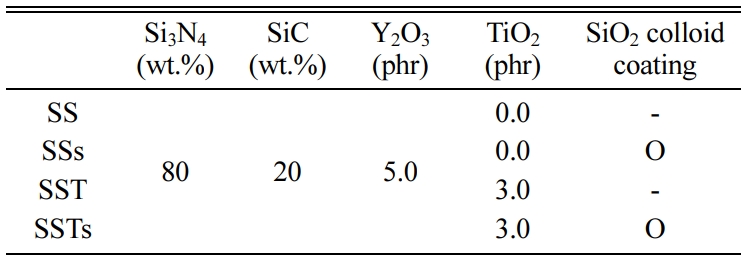
The Si3N4 powder used in this study had an average particle size of 0.2 µm. The volume ratio of α- Si3N4 was more than 95%, and the remains consisted of β-Si3N4. The size of the SiC powder was 0.27 μm. The TiO2 powder was a commercial anatase type. Y2O3 of 33 nm was used as the sintering aid. SiO2 colloid was coated on the surface to investigate the wear characteristics. Table 1 shows the compositions of each specimen.
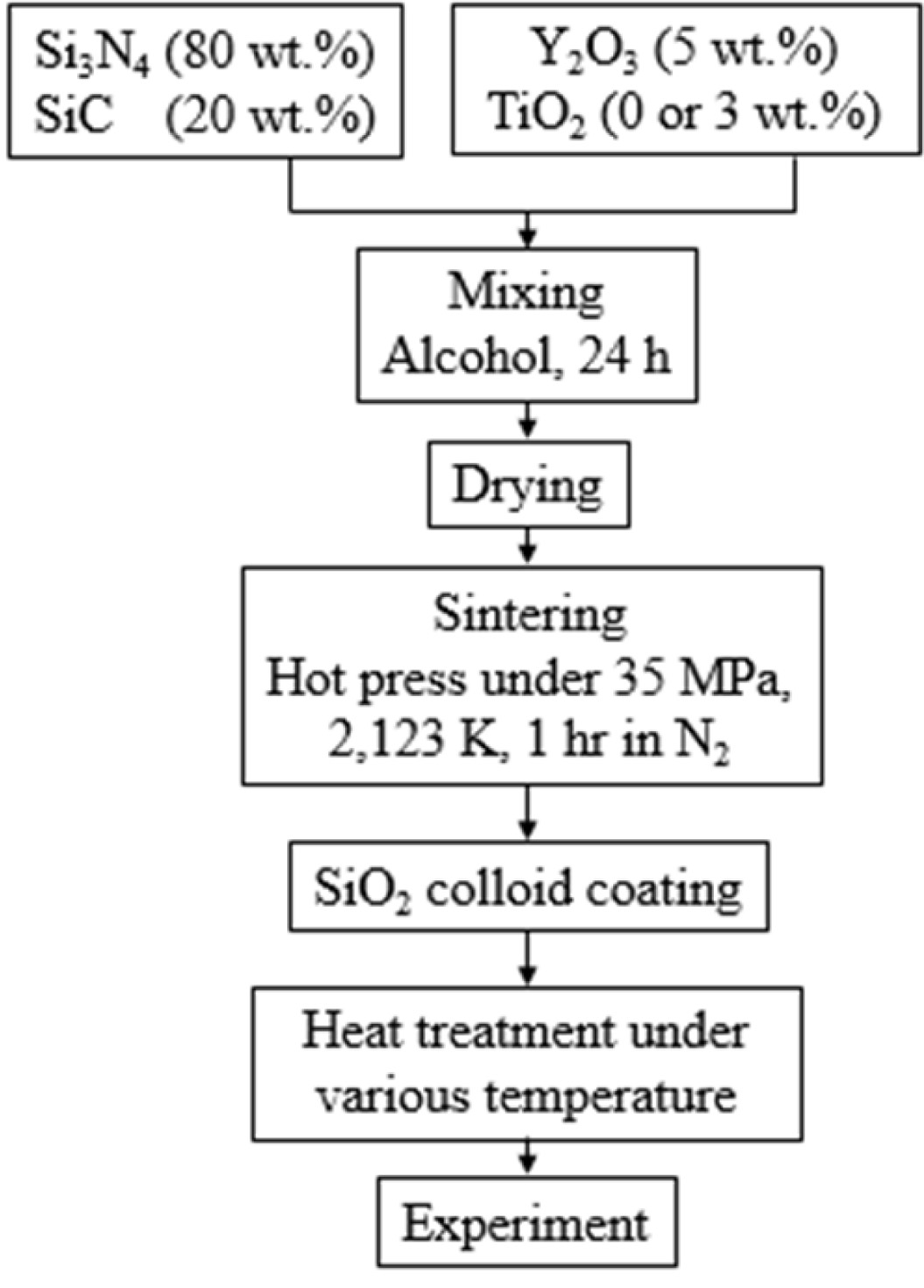
The powder was mixed for 24 h by adding Si3N4 balls and alcohol. The mixed powder was dried in a vacuum furnace until the solvent evaporated, and then powder was used for sintering. Sintering was performed at 2,123 K for 1 h under 35 MPa of N2 gas atmosphere. The sintered material was cut to 3 mm × 4 mm × 10 mm, and then mirror polished. A crack of about 100 mm length was made in the polished specimen by Vickers indentation. The crack specimen was coated with SiO2 colloid on the surface, and heat-treated in the atmosphere at (500-1,300) oC for 1 h. The specimens were coated (1 and 3) times to evaluate the wear characteristics according to the number of coatings of the SiO2 colloid, and heat-treated at 1,000 oC for 1 h [15]. Five pieces of wear specimens were used in each condition. Fig. 1 shows a flow chart of the sintering and specimen preparation. The counterpart of the Si3N4/SiC specimen is QT vacuum heat-treated SKD11 having a diameter of 35 mm and a thickness of 7 mm. The test conditions were as follows: (1) the rotation speed of the ring which has a dimension of 35 mm was 50 rpm; (2) the load was 9.8 N; (3) the total wear distance was 500 m; and (4) the tests were performed at room temperature in a dried condition. To obtain high reliability, 55,000 data that were obtained at 10 data per second were used. After the wear test, the worn surface was characterized using a scanning electron microscope (SEM, VEGAII XMU, Tescan, Czech) coupled with an energy dispersive spectroscopy detector (EDX, INCA, Germany).
|
Fig. 1 Flow chart of sintering |
Bending strength
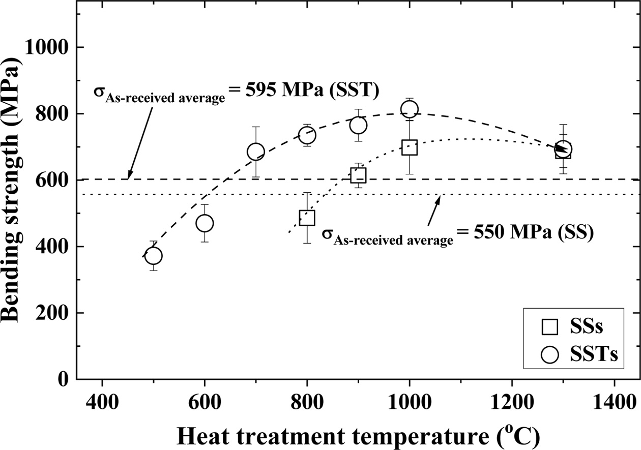
Fig. 2 shows the relationship between the heat treat- ment temperature and the bending strength according to the additive TiO2 and the coating substance SiO2. In the figure, the square (□) indicates Si3N4/SiC coated with SiO2 colloid (SSs), while circle (○) indicates Si3N4/SiC-TiO2 coated with SiO2 colloid (SSTs). The average of bending strength of the as-received specimen (SS and SST) without SiO2 colloid coating was (550 and 595) MPa, respectively. The bending strength of SST with additive TiO2 was about 8% higher than that of SS without additive TiO2. SST showed an increased sintering property, and is believed to have improved strength. On the other hand, SiO2 colloid coated crack specimens showed a difference in strength, depending on the heat treatment temperature. SSs and SSTs specimens showed higher strength than SS and SST specimens at above (900 and 700) oC, respectively. This is because the crack was completely healed by the SiO2 coating. The optimum heat treatment conditions for the SSs and SSTs specimens were 1,000 oC, and the strength of both specimens were decreased at 1,300 oC. This is because the healed cracks turned into notches when the temperature increased [21]. At an optimum temperature of 1,000 oC, the bending strength of SSTs specimens was increased by about 37%, compared to that of SST specimens. SSs specimens showed about 27% higher bending strength than the SS specimens. In addition, the bending strength of SSTs specimens with additive TiO2 was increased by about 16% more than that of the SSs specimens. This is because TiO2 addition increased the sintering force, and micro surface cracks were completely healed by the coating of SiO2 colloid.
Wear characteristics of crack-healed specimens
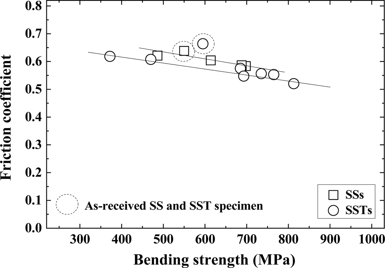
Fig. 3 shows the relationship between bending strength and friction coefficient. The dotted circles in the figure represent the friction coefficients of the as-received SS and SST specimens. The square (□) and circle (○) indicate SiO2 colloid coated SSs specimens and SSTs specimens, respectively. In this figure, the friction coefficient is inversely related to the bending strength. That is, the friction coefficient decreases as the bending strength increases. Also, the coefficients of friction of SSTs specimens are smaller than those of SSs specimens. The friction coefficients of the as-received SS specimens agree well with those of the SSs specimens, but those of the as-received SST specimens are slightly larger than those of the SSTs specimens. However, the friction coefficients become small as the bending strength increases.
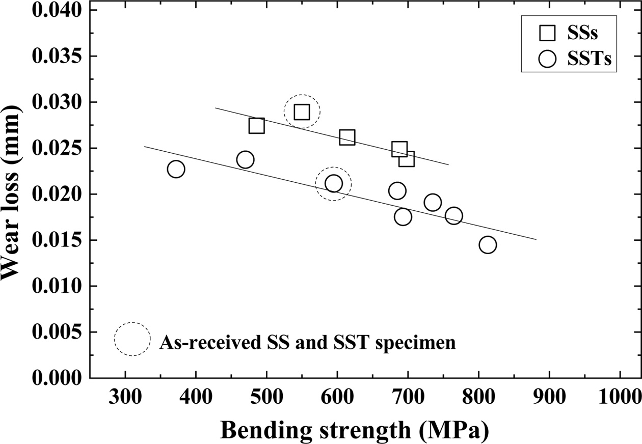
Fig. 4 shows the relationship between bending strength and wear loss. The dotted circles in the figure represent the wear loss of as-received SS and SST specimens. The square (□) and circle (○) indicate the SiO2 colloid coated SSs specimen and SSTs specimen, respectively. In this figure, wear loss is inversely related to the bending strength. That is, wear loss decreases as bending strength increases. Also, the wear loss of the SSTs specimen is smaller than that of the SSs specimen. The wear loss of the as-received specimens is consistent with the temperature dependence of the SSs and SSTs specimens, respectively. The wear loss decreases as the bending strength increases. The wear losses of the SSTs and SSs specimen are greater than the difference between the friction coefficients.
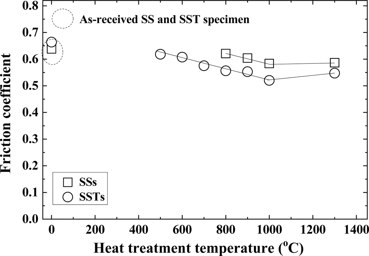
Fig. 5 shows the relationship between the heat treatment temperature and friction coefficient. The dotted circles in the figure represent the friction coefficients of the as-received SS and SST specimens. The square (□) and circle (○) indicate the SiO2 colloid coated SSs specimen and SSTs specimen, respectively. The friction coefficients of the as-received SS and SST specimens are slightly larger than that of the lowest temperature of the heat-treated specimen. The friction coefficient of the heat-treated specimen showed similar tendency to the bending strength. That is, as the heat treatment temperature increases, the bending strength increases, and then decreases. However, the friction coefficient decreased and then increased. In other words, it showed the reverse tendency to the bending strength.
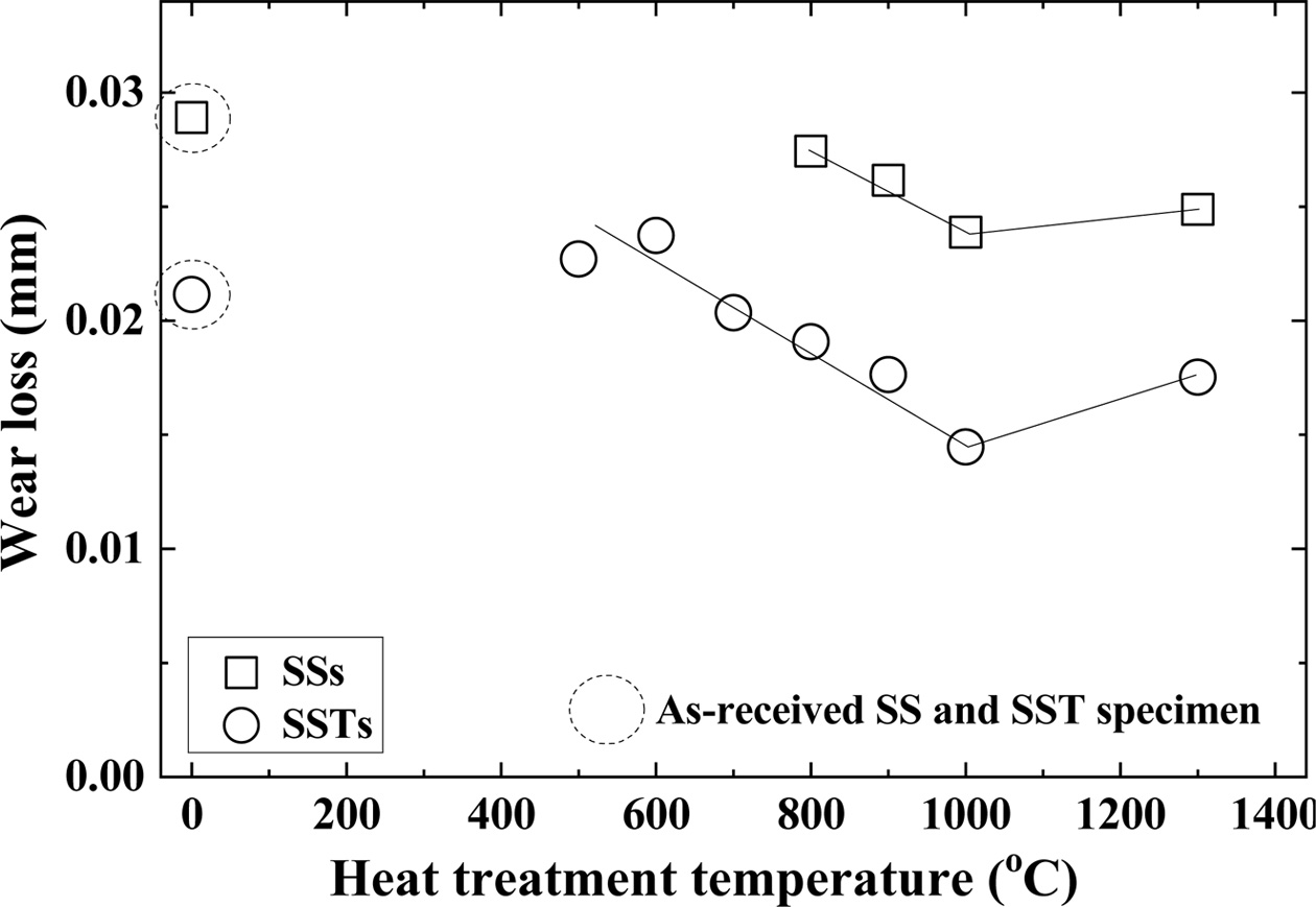
Fig. 6 shows the relationship between heat treatment temperature and wear loss. The dotted circles in the figure represent the wear loss of the as-received SS and SST specimens. The square (□) and circle (○) indicate the SiO2 colloid coated SSs specimen and SSTs specimen, respectively. The wear loss of the as-received specimens is almost the same as that of the lowest temperature of the heat-treated specimen, respectively. The wear loss of the heat-treated specimens was inverse to the bending strength. That is, with increasing heat treatment temperature, wear loss decreased, and then increased.
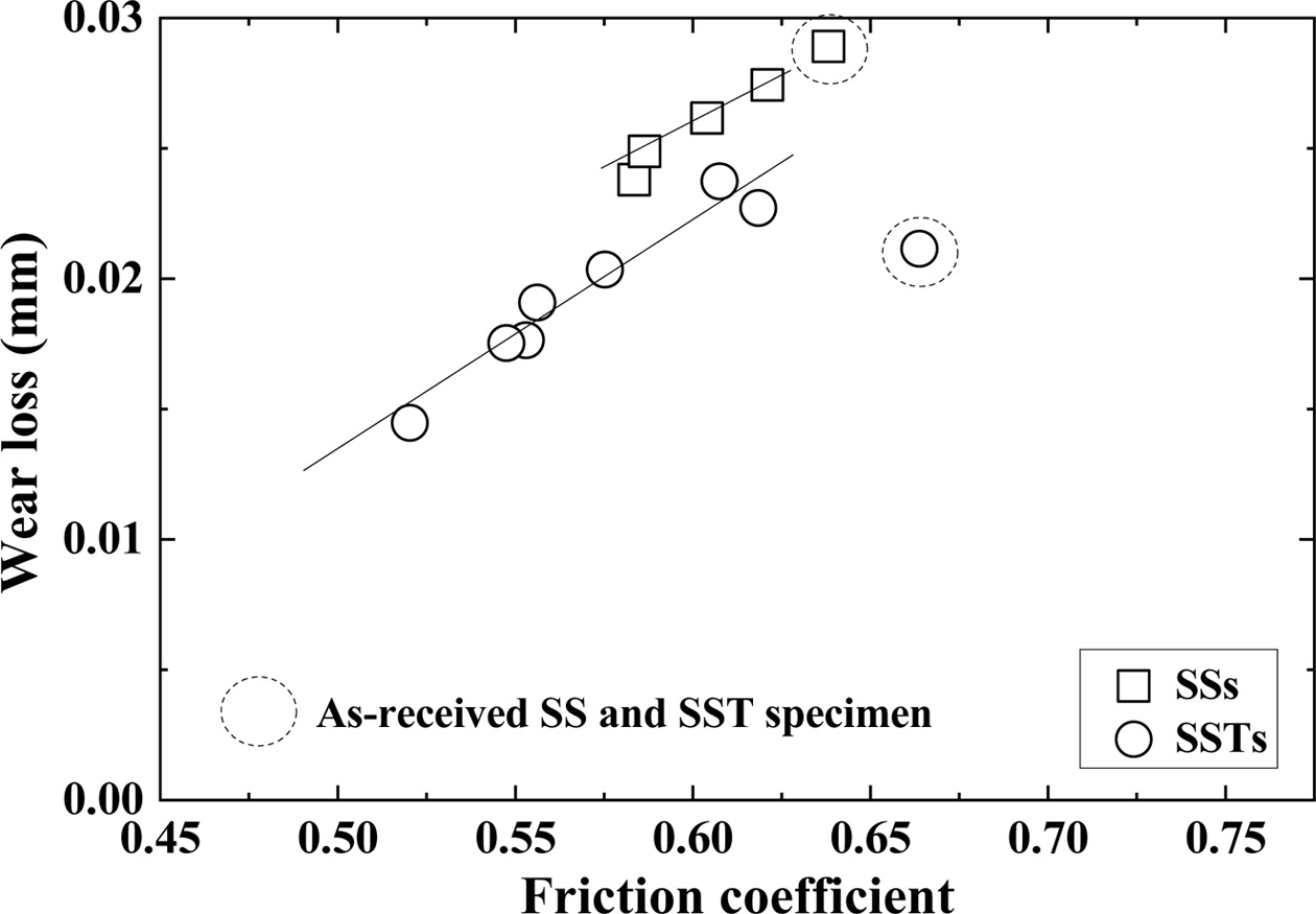
Fig. 7 shows the relationship between the wear loss and friction coefficient. The dotted circles in the figure represent as-received SS and SST specimens. The square (□) and circle (○) indicate the SiO2 colloid coated SSs specimen and SSTs specimen, respectively. The wear loss and friction coefficient are proportional to each other. The wear loss of the as-received SS specimen is on the same line as that of the SSs specimen, but the as-received SST specimen does not show linear relation- ship with the SSTs specimen. Although the friction coefficient of SST specimen is large, the wear loss is small. Overall, the wear loss is shown to be inversely related to the bending strength.
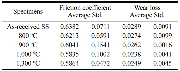
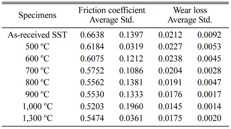
Tables 2 and 3 show the average of the friction coefficient, wear loss, and standard deviation (Std) of the SSs specimen and SSTs specimen in different heat treatment temperature.
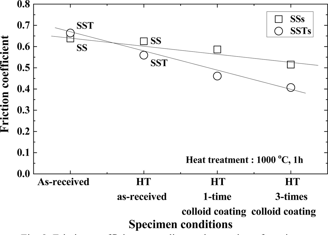
Fig. 8 shows the coefficient of friction depending on the number of coatings. In the figure, HT means heat treatment. Heat treated (HT) as-received specimens have smaller friction coefficients than the as-received specimens in both SS and SST specimens. This is because the micro cracks are healed by heat treatment, and the strength is increased. The HT 1-time colloid coating specimen has a smaller friction coefficient than the as-received HT specimen. The HT 3-times colloid coating specimen showed the smallest friction coefficient. This was cured by repetition of the heat treatment after coating, and it is believed that SiO2 that formed on the surface provided lubrication. The coefficient of friction is smaller for SSTs specimens with TiO2. This is in good agreement with the high tensile strength.
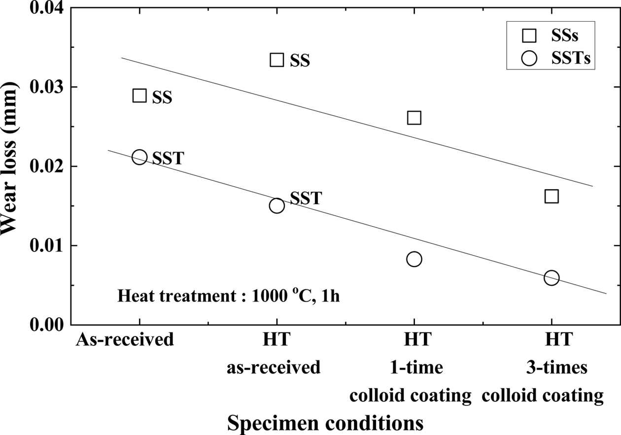
Fig. 9 shows the wear loss according to the number of coatings. Wear loss also showed the same tendency as the friction coefficient. In other words, the friction coefficient is in the order: as-received specimen > HT as-received specimen > HT 1-time colloid coating specimen > HT 3-times colloid coating specimen. The wear loss of the SSTs specimens was about 34% smaller than that of the SSs specimens. The difference of wear loss between the two specimens was greater than the difference of the friction coefficient. This is a good match with the high tensile strength of the SSTs specimens with TiO2.
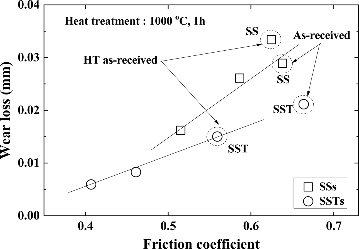
Fig. 10 shows the relationship between the friction coefficient and wear loss. The friction coefficient and wear loss are proportional to each other. The wear loss and friction coefficients of both the SSs and SSTs specimens were smaller than those of the SS and SST specimens. This is determined to be an effect of the healing substance SiO2 formed in the surface by heat processing. The friction coefficient and wear loss decreased with the number of coatings. This was because SiO2 acted as a healing substance, and extra SiO2 acted as a lubricating substance.
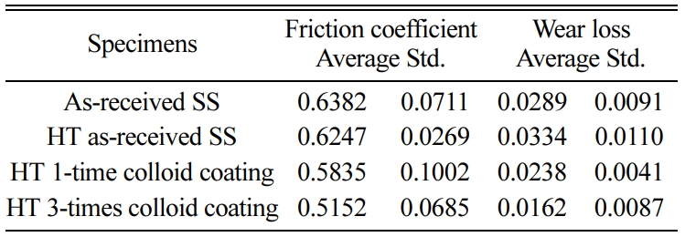
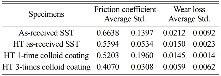
Tables 4 and 5 show the average of friction coefficient, wear loss, and standard deviation (Std) of the SSs and SSTs specimens, according to the number of coatings.
Fig. 11 shows the representative optical micrographs obtained from the SSs specimen after the wear test. In the figure, the wear part is observed as a scratched or a striped shape, regardless of the heat treatment tempera- ture. This is the behavior of abrasive wear. Abrasive wear is responsible for 50% of the loss caused by wear. This is the main mechanism in the deformation by micro shear. The specimens showed slightly different surface color, according to the heat treatment tempera- ture. This indicates the degree of oxidized surface, according to the heat treatment temperature. The black area is also determined to be affected by the heat treatment.
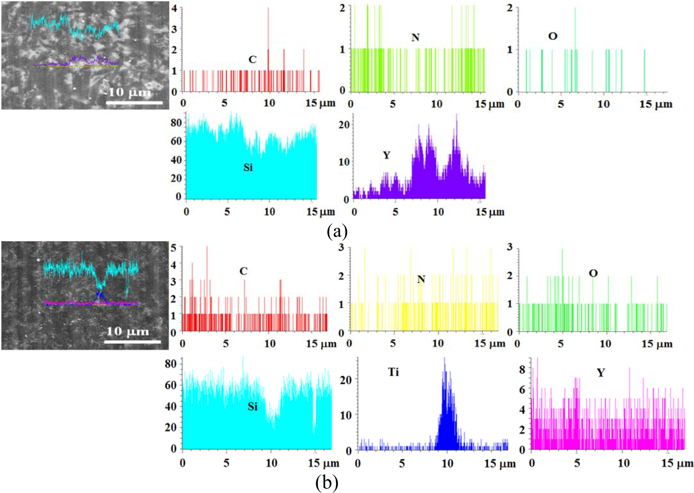
Fig. 12 shows the line profile for the surface of an as-received specimen. Figs. 12(a) and (b) show the SS specimen and SST specimen, respectively. These specimens are not coated with SiO2 colloid. In Figs. 12 (a) and (b), a large amount of Si and a small amount of N and C were detected, and a little O was detected, due to the sintering effect. In addition, Y of the sintering additive Y2O3 was detected. On the other hand, Ti was detected in the TiO2-added SSTs specimen.
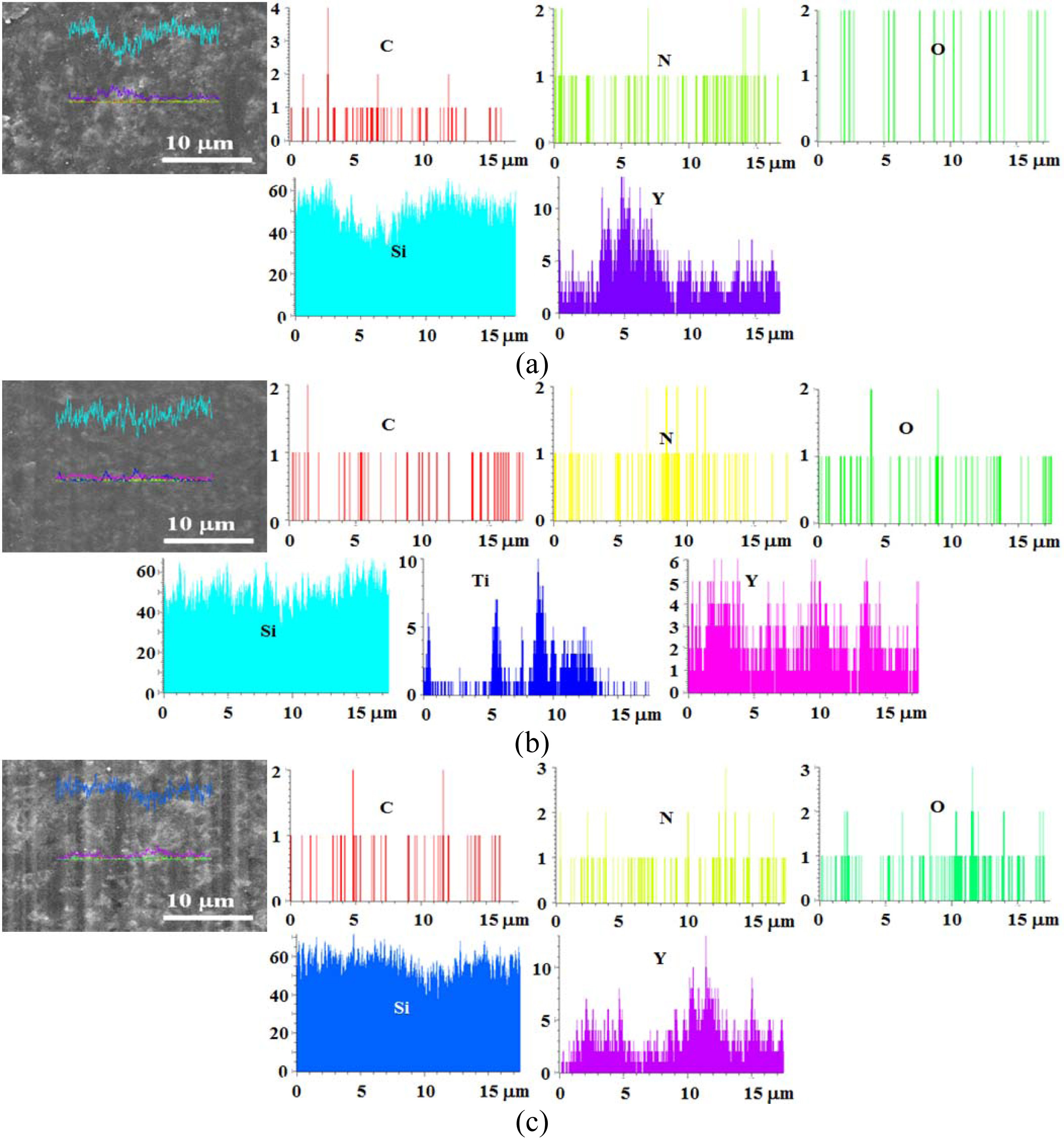
Fig. 13 shows the line profile on the surface for an as-received specimen of heat treatment temperature 1,000 oC. Figs. 13 (a) and (b) show the SSs specimen and SSTs specimen, respectively. Fig. 12 is similar to that described in Fig. 11, in that in (a) and (b), Si was the most, a small amount of N and C was detected, and some O was detected by the effect of heat treatment. In addition, Y of a sintering additive Y2O3 was detected. (c) shows the 3-times colloid coated SSs specimen with heat-treatment at 1,000 oC. These elements were also detected in the SS specimens. The line profile could not specify the amount of each element depending on the number of coatings.
|
Fig. 2 Heat treatment temperature dependence of the bending strength in accordance with SiO2 colloid coating. |
|
Fig. 3 Relationship between bending strength and friction coefficient. |
|
Fig. 4 Relationship between bending strength and wear loss |
|
Fig. 5 Relationship between friction coefficient and heat treatment temperature |
|
Fig. 6 Relationship between wear loss and heat treatment temperature. |
|
Fig. 7 Relationship between wear loss and friction coefficient. |
|
Fig. 8 Friction coefficient according to the number of coatings. |
|
Fig. 9 Wear loss according to the number of coatings. |
|
Fig. 10 Relationship between wear loss and friction coefficient. |

|
Fig. 11 Wear surfaces according to heat treatment temperature of SSs specimens with colloid coating. (a) As-received SS, (b) 800 oC, (c) 900 oC, (d) 1,000 oC, (e) 1,300 oC. |
|
Fig. 12 Line profile for as-received specimens. (a) SS specimen, (b) SST specimen. |
|
Fig. 13 Line profile for SiO2 colloid coated specimens with heat treatment at 1,000 C. (a) SSs specimen, (b) SSTs specimen, (c) SSs specimen with 3-times coating. |
|
Table 2 Friction coefficient and wear loss of the SSs specimen in different heat treatment temperature. |
|
Table 3 Friction coefficient and wear loss of the SSTs specimen in different heat treatment temperature. |
|
Table 4 Friction coefficient and wear loss of the SSs specimen according to the number of coatings. |
|
Table 5 Friction coefficient and wear loss of the SSTs specimen according to the number of coatings. |
This study added TiO2, and evaluated the bending strength and wear characteristics of Si3N4/SiC composites coated with healing substance SiO2. The results obtained are as follow:
SiO2 colloid coated specimen had higher strength than the uncoated specimen, and the strength of specimen added with TiO2 also increased. This is because TiO2 increased the sintering force, and the coating of SiO2 colloid completely healed the surface micro cracks.
The friction coefficient and wear loss of SiO2 colloid coated specimens were smaller than those of the uncoated specimens. The friction coefficient and wear loss of TiO2-added specimens were smaller than those without additives. The friction coefficient and wear loss decreased with increasing bending strength, and were proportional between the two. Friction coefficient and wear loss according to the heat treatment tempera- ture showed the reverse tendency to the bending strength.
The friction coefficient and wear loss of heat-treated specimen at 1,000 oC were smaller than those of the non-heat treated specimen, and those of the SiO2 colloid 3-times coated specimen were smaller than those of the 1-time coated specimen. The extra SiO2, which acted as a healing substance, also acted as a lubrication material.
The wear surface showed the behavior of abrasive wear, regardless of the material and heat treatment temperature. Each component was detected in the line profile of the specimen surface, but the amount of each element could not be specified.
It was found that additive TiO2 and SiO2 to Si3N4/SiC composites showed the highest bending strength as well as the lowest friction coefficient and wear loss compared with the other specimens. With heat treat- ment at 1,000 oC, the friction coefficient and the wear loss can be further decreased. Taking the experimental result into consideration, the processes and materials for ceramic production requires more that may incur increase in the production cost. However, when it comes for commercial use, it is argued that it can improve the mechanical efficiency due to the high wear resistance and low friction. This may increase a chance to prevent machinery operation from failure, and to save the costs for replacement and maintenance. Therefore, TiO2-added ceramics will ensure economic efficiency.
- 1. N. Nakamura, K. Hiraoand, and Y. Yamauchi, J. Eur. Ceram. Soc. 24[2] (2004) 219-224.
-

- 2. M. Maros, A.K. Németh, Z. Károly, E. Bódis, Z. Maros, O. Tapasztó, and K. Balázsi, Tribol. Int. 93 (2016) 269-281.
-

- 3. H. Klemm, J. Am. Ceram. Soc. 93[6] (2010) 1501-1522.
-

- 4. M. Herrmann, J. Am. Ceram. Soc. 96[10] (2013) 3009-3022.
-

- 5. M.B. Marosand A.K. Németh, J. Eur. Ceram. Soc. 37[14] (2017) 4357-4369.
-

- 6. K. Ando, M.C. Chu, S. Sato, F. Yao, and Y. Kobayashi, Jpn. Soc. Mech. Eng. 64[623] (1998) 1936-1942.
-

- 7. K. Ando, M.C. Chu, F. Yao, and S. Sato, Fatigue Fract. Engng. Mater. Struct. 22[10] (1999) 897-903.
-

- 8. F. Yao, K. Ando, M.C. Chu, and S. Sato, J. Eur. Ceram. Soc. 21[7] (2001) 991-997.
-

- 9. K. Ando, K. Houjyou, M.C. Chu, S. Takeshita, K. Takahashi, S. Sakamoto, and S. Sato, J. Eur. Ceram. Soc. 22[8] (2002) 1339-1346.
-

- 10. K. Takahashi, Y.S. Jung, Y. Nagoshi, and K. Ando, Mater. Sci. Eng. A 527[15] (2010) 3343-3348.
-

- 11. K. Takahashi and Y. Nishio, J. Solid Mech. Mater. Eng. 6[2] (2012)144-153.
-

- 12. M.K. Kim, H.S. Kim, S.B. Kang, S.H. Ahn, and K.W. Nam, Solid State Phenom. 124-126(2007) 719-722.
-

- 13. K.W. Nam, M.K. Kim, S.W. Park, S.H. Ahn, and J.S. Kim, Mater. Sci. Eng. A 471[1-2] (2007) 102-105.
-

- 14. K.W. Nam, S.H. Park, and J.S. Kim, J. Ceram. Process. Res. 10[4](2009) 497-501.
- 15. K.W. Nam and J.S. Kim, J. Ceram. Process. Res. 11[1] (2010) 20-24.
- 16. K.W. Nam, J.S. Kim, and H.B. Lee, Trans. of the KSME, A 33[7] (2009) 652-657.
-

- 17. M.S. Gok, O. Gencel, V. Koc, Y. Kuchuk, and V.V. Cay, Powder Metall. Met. Ceram. 50[5] (2011) 322-330.
-

- 18. J.A. Hawk, D.E. Alman, and J.J. Petrovic, J. Am. Ceram. Soc. 79[5] (1996) 1297-1302.
-

- 19. S. Wada and Y. Kumon, J. Ceram. Soc. Jpn. 101[1175] (1993) 830-834.
-

- 20. K.W. Nam, J. Ceram. Process. Res. 13[5] (2012) 571-574.
- 21. S.K. Lee, W. Ishida, S.Y. Lee, K.W. Nam, and K. Ando, J. Eur. Ceram. Soc. 25[5] (2005) 569-576.
-

 This Article
-
2021; 22(1): 66-73
Published on Feb 28, 2021
- 10.36410/jcpr.2021.22.1.66
- Received on Jul 17, 2020
- Revised on Aug 15, 2020
- Accepted on Sep 3, 2020
 Services
- Abstract
introduction
materials and experiment methods
results and discussion
conclusions
- References
- Full Text PDF
Shared
 Correspondence to
- Ki-Woo Nam
-
Dept. of Materials Science and Engineering, Pukyong National Univesity, 45 Yongso-ro, Nam-gu, Busan 48513, Korea
Tel : +82-51-629-6358 Fax: +82-51-629-6353 - E-mail: namkw@pknu.ac.kr


 Copyright 2019 International Orgranization for Ceramic Processing. All rights reserved.