- Optimization of friction stir welding process parameters on AA 6063-SiC-B4C hybrid metal matrix composites by genetic algorithm
R. Srinivasana, B. Suresh Babub,*, P. Prathapc, Ruban Whenishd, R. Soundararajane and G. Chandramohanf
aProfessor, Department of Mechanical Engineering, Sri Krishna College of Technology, Coimbatore, Tamil Nadu, India
bAssistant Professor, Department of Mechanical Engineering, Sri Krishna College of Technology, Coimbatore, Tamil Nadu, India
cProfessor, Department of Mechanical Engineering, Sri Krishna College of Technology, Coimbatore, Tamil Nadu, India
dApplication Engineer, Manna chemicals and Drugs Private Limited, Chennai, Tamil Nadu, India
eAssociate Professor, Department of Mechanical Engineering, Sri Krishna College of Engineering and Technology, Coimbatore, Tamil Nadu, India
fProfessor, Department of Mechanical Engineering, P.S.G Institute of Technology and Applied Research, Coimbatore, Tamilnadu, IndiaThis article is an open access article distributed under the terms of the Creative Commons Attribution Non-Commercial License (http://creativecommons.org/licenses/by-nc/4.0) which permits unrestricted non-commercial use, distribution, and reproduction in any medium, provided the original work is properly cited.
Friction Stir Welding (FSW) is a metal joining process has its own benefits over fusion welding processes. FSW Aluminium Metal Matrix Composites (AMMC) replaced conventional metals for structural applications in aerospace, automobile and marine sectors. In this present investigation, process parameters of FSW for joining AA 6063-SiC-B4C hybrid MMCs were optimized in order to achieve maximum tensile strength. Initially, AMMC was manufactured through stir casting with the matrix AA 6063 and reinforcements SiC and B4C. The hybrid MMC work pieces were subjected to FSW process by varying the process parameters such as tool rotation speed, welding speed and axial force using Taguchi L27 orthogonal array. Tensile strength of hybrid composite was examined and regression analysis were done using MINITAB V17 software. Genetic Algorithm technique was used to optimize the tensile strength with FSW parametric combinations. The optimum parameters for FSW of AA6063-SiC-B4C hybrid composites were Tool rotational speed (TRS) – 1050 rpm; Axial Force (AF) – 10 kN and Weld Speed (WS) – 45 mm/min obtained. The optimal parameters were applied to experimental study and the results were validated
Keywords: Hybrid metal matrix composite, Stir Casting, FSW, Genetic algorithm, Tensile strength
Composite materials are composed with matrix and reinforcements, possessing combined properties which enhances the material for specific applications [1]. Aluminium based composites are replaced conventional materials due to their wide alloy range and processing flexibility in many structural applications [2]. Hybrid Aluminium Metal Matrix Composites (HAMMCs) have been appropriate for applications which necessitate characteristics such as combined strength, thermal conductivity, etc. Corrosion resistance and wear resistance enhance their tribological applications in pistons, brake drum, brake parts in automotive [3]. The study of reinforcements like fibers, whiskers and particulates which have been employed particularly in aluminium alloys leading to a tailor-made engineering materials with specified properties [4]. The addition of hard ceramic particles like SiC, Al2O3, B4C etc., results in enhanced wear resistance and strength to weight ratio than that of the conventional alloys [5]. Al2O3, SiC and B4C have been the appropriate particulate reinforcing material for Al-MMCs, as it has good compatibility with aluminium even at the projected temperatures. The tensile strength and hardness were improved and toughness was reduced by adding the SiC and Al2O3 hard particles [6]. The most effective fabrication methodology followed for making composite materials has been known as the vortex technique or stir-cast method. Selection of process parameters playing vital to produce quality composites. Al 6061/B4C MMCs were fabricated using stir casting technique and inves- tigated the significance of B4C in MMCs through mechanical and microstructural analysis [7]. Stir casting is a simplest fabrication method to produce hybrid MMCs with good miscibility. The tensile strength and yield strength of SiC and Al2O3 filled Al 7075 alloy composites were found to increase with addition of reinforcements [8]. The influence of SiC and B4C particulates in Al6061 matrix having SiCp-5, 10, 15 wt.%, B4C-3 wt.% and particle size 30-70 μm for SiC and 5-20 μm for B4C prepared by stir cast process. The metallographic study depicts a homogeneous distribution of reinforcements [9].
Friction Stir Welding (FSW) is a metal joining process producing high quality weld joints with cost effective. FSW joints were resulted in obvious homogenization and fragmentation of B4C hard particles which has increased the hardness of welding zones. Welding speed significantly influence the hardness and tensile strength of weld joints [10, 11]. The impact of welding speed (WS) in FSW were investigated in this approach. Different WS were maintained from 50 mm/min to 175 mm/min with other constant FSW parameters for joining alloys. The tensile strength of 80 MPa was achieved with lower WS of 50 mm/min and WS of 175 mm/min has received tensile strength of 71 MPa. Due to generation of insufficient heat input at higher WS shows lower tensile strength [12].
A study has made in FSW, to assess the influence of tool rotational speed (TRS) on mechanical and metallography analysis. TRS with 600, 950, 1,300 and 1,650 rpm weld joints were made. From the results, the highest TRS led to reduce the grain refinement or grain coarsening and with low TRS values kept significant grain refinement. But the materials mixing were limited with lower TRS [13]. In another study, TRS in FSW process on AA6092/17.5 SiCp-T6 composites were investigated. TRS has maintained in 3 levels as 1000 rpm, 1,500 rpm and 2000 rpm and other parameters were kept as constant. 6 mm thick plates were welded by varying the TRS. At high TRS 2,000 rpm, the particles were migrated from its place. The maximum tensile strength was achieved at 1,500 rpm with 84% joint efficiency and minimum tensile strength was obtained with lower TRS speed at 1,000 rpm with 68% efficiency [14]. The influence of Welding Speed (WS) in FSW process over aluminium alloys was observed that decreasing the WS increases the ultimate strength of the FSW joints [15, 16]. The overall quality FSW joints were highly influenced by welding parameters. High WS leads to formation of welding defects such as tunnel defects, improper penetration and cavity [17]. In FSW, Tool travel speed (TTS) and TRS had major impact on weld quality and mechanical properties. When TTS was increased, B4C particles were distributed homogeneously in the aluminium matrix. TRS in peak temperature helped to obtain the improved tensile strength of the composites [18].
In another study, Al alloy AA5052-H32 and HSLA steel IRS-M42-97 of 3mm thickness were butt welded using FSW technique. The axial forces (AF) were varied from 4 to 9 kN and keeping the other FSW parameters as constant. The highest weld joint strength of 189 MPa was obtained at 7 kN axial force. It is observed that, the influence of AF that could produce joints with good strength [19]. Tool pin profile plays a key role in terms of material flow and control in FSW process [20]. In a study, AMMC using different profiles of tools with different tool materials and D/d ratio 2, 3, 4 on a commercial CNC enabled FSW machine. From the results, it was observed that the effect of tool profile makes an impact in terms of quality of weld joints [21].
Ho et al. 2016 proposed IHTGA (Intelligent hybrid Taguchi-genetic algorithm) that performed Taguchi method between the crossover operation of GA, where the genes for crossover are selected intelligently using Taguchi to get the enhanced performance results in the optimization of bearing offsets and shaft alignment in a marine vessel propulsion system [22]. Among the enormous varieties of aluminium alloys, AA 6063 was preferred as a better choice, because of the formability characteristics and the possibilities of modifying the strength of the composite by employing optimal heat treatment. The specific characteristics such as better wettability, strength of SiC and B4C, adds more com- patible with the aluminium matrix as reinforcements [23, 24]. Thus based on literature study, the present investigation proposed with SiC and B4C as the reinforcement materials with AA 6063 matrix for the fabrication of HMMCs by stir casting. The stir casted hybrid composites further processed with FSW in order to find out tensile characteristics of hybrid composites and the influence of FSW process parameters. The influencing FSW parameters were identified by Genetic Algorithm methodology.
Preparation of hybrid composite
AA6063-SiC-B4C Hybrid Composite is manufactured by using stir casting technique, prior to the FSW process. The chemical composition of AA 6063 alloy are shown in Table 1. AA 6063 is one of the aluminium alloy with better properties in 6XXX alloys such as high fatigue strength and good corrosion resistance [25]. The alloy is being replaced by hybrid composite in the components of rib and wing structures in aircrafts. AA 6063 alloy was used as a matrix B4C with a size of 30 microns and silicon carbide with a size of 33 microns were used as a reinforcements. In stir casting technique, Aluminium billets placed in a graphite crucible were heated to temperature of around 730 oC. Meantime, the reinforcements SiC and B4C each 10% of weight were preheated to 900 oC in a muffle furnace for a soaking time of one hour to remove the moisture content. Mg powder of 1% of weight was added into the melt to improve the wettability factor of reinforcements. Preheated reinforcements were added with AA 6063 through a feeder and it was stirred well for 30 min. The dimension of 100 mm × 100 mm × 10 mm was which was preheated to around 300 oC to promote gradual heat dissipation from the melt.
Friction Stir Welding of hybrid composites
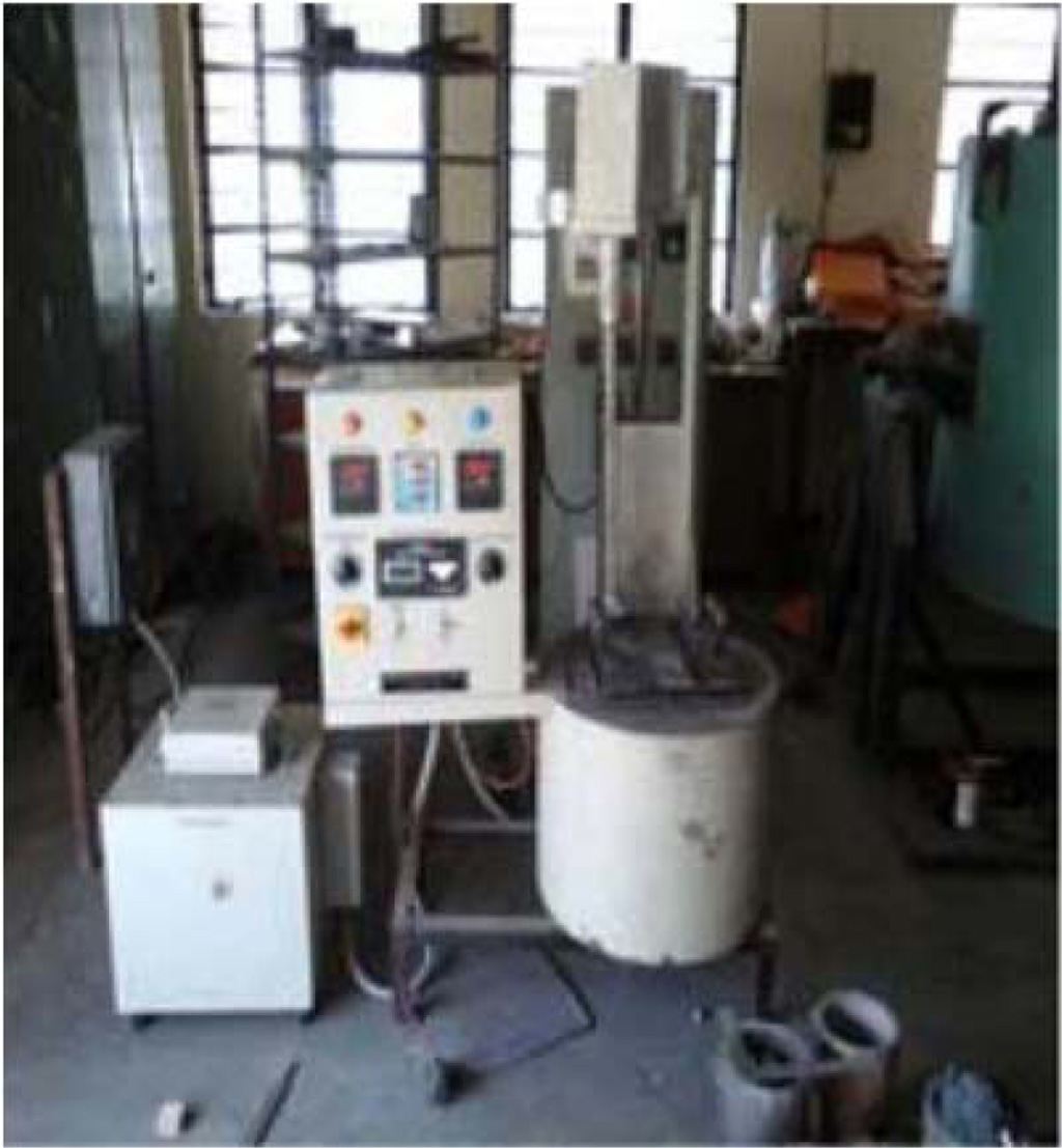
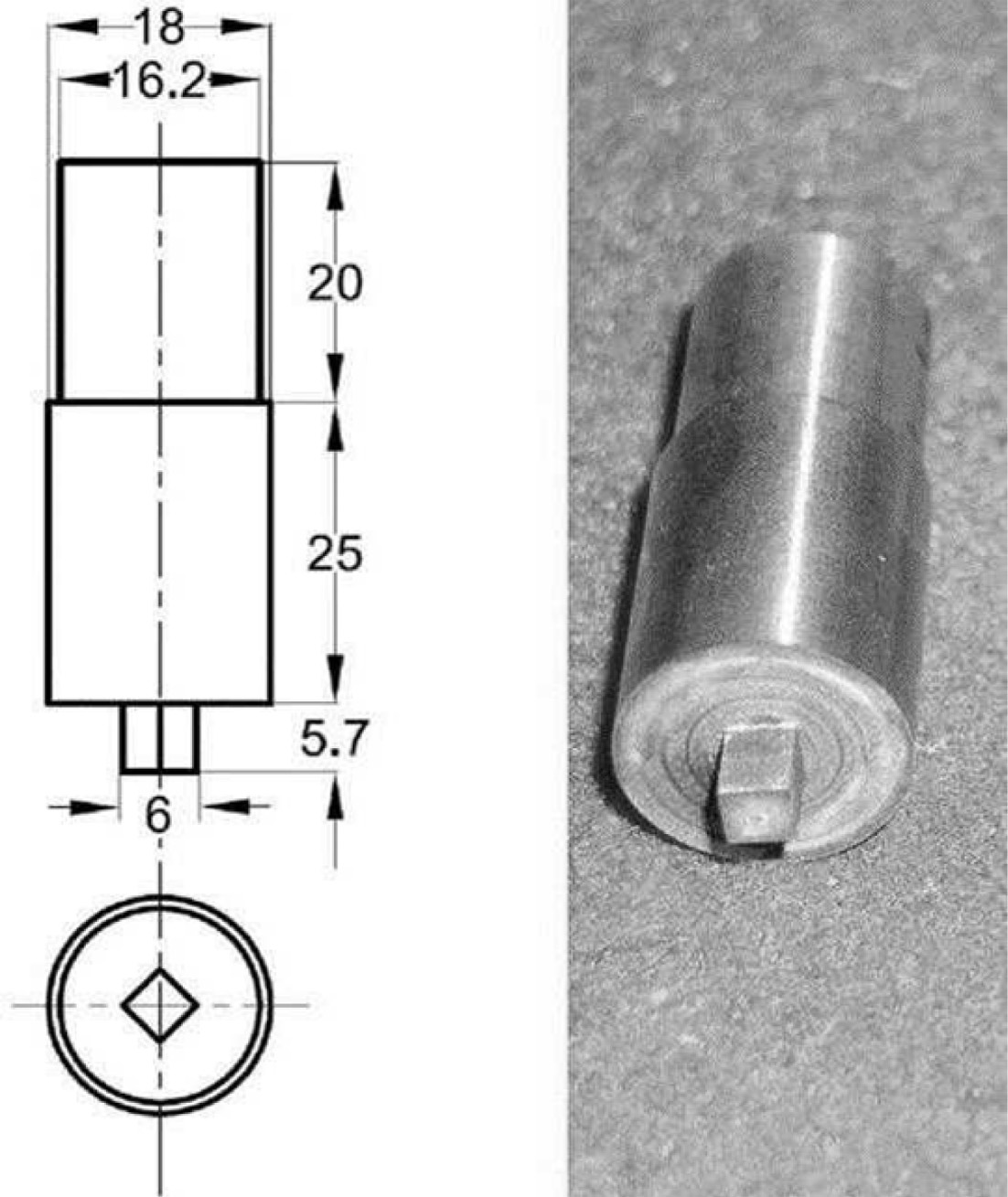
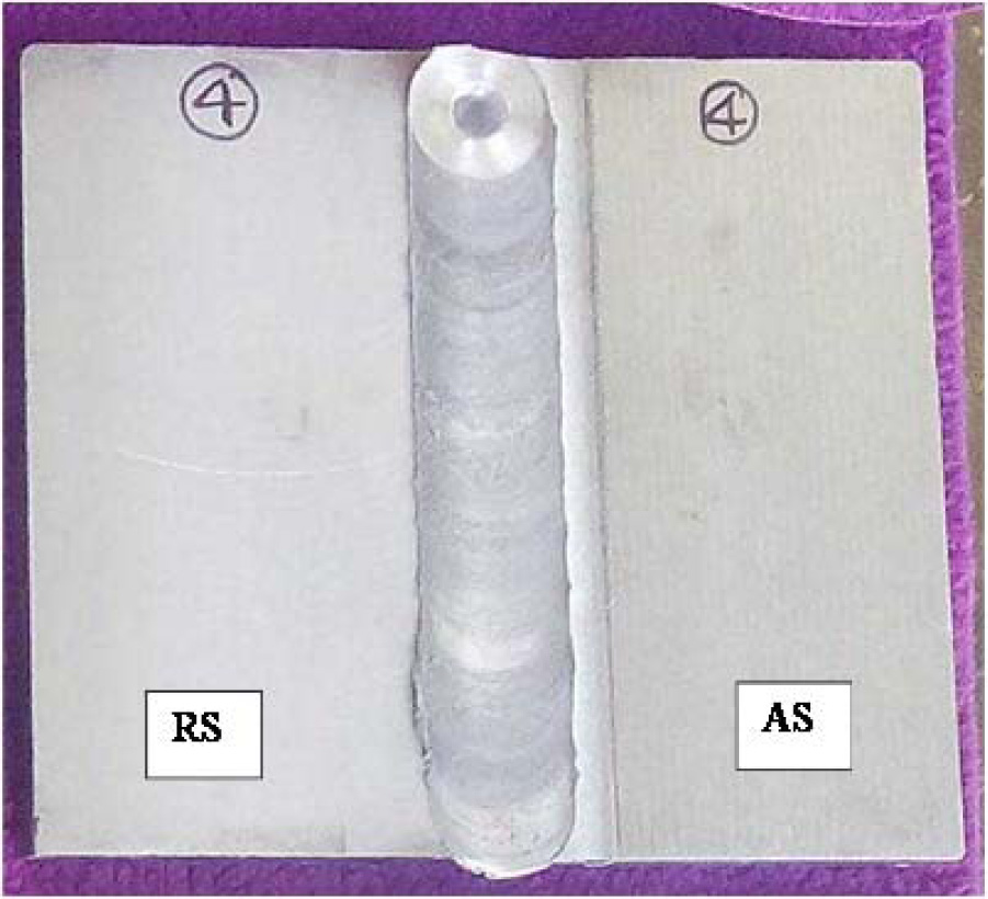
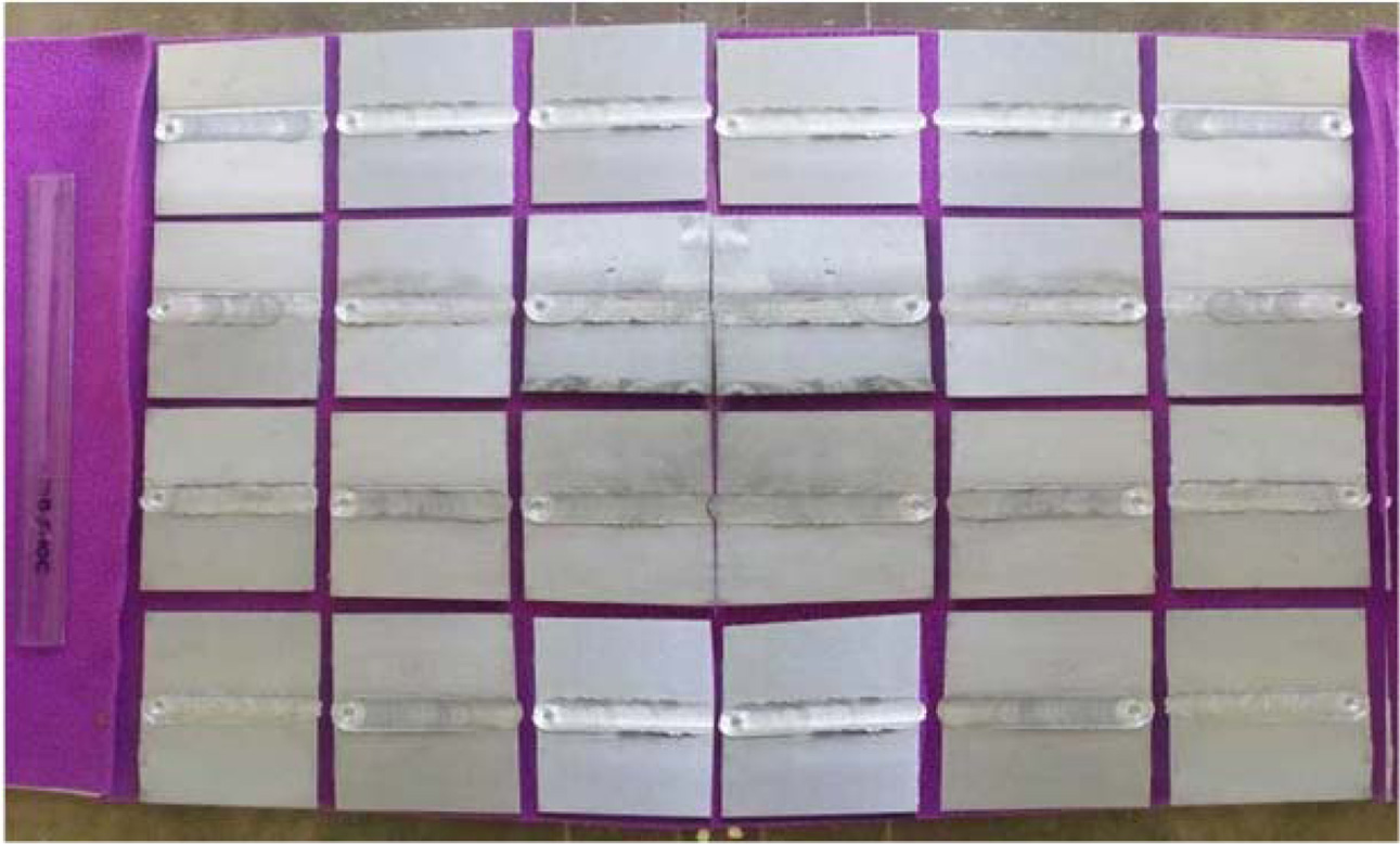
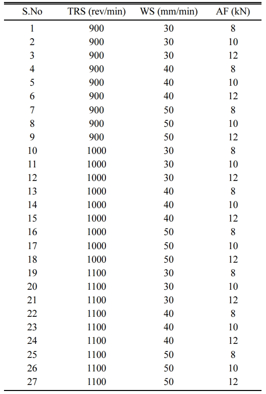
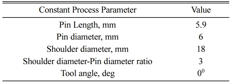
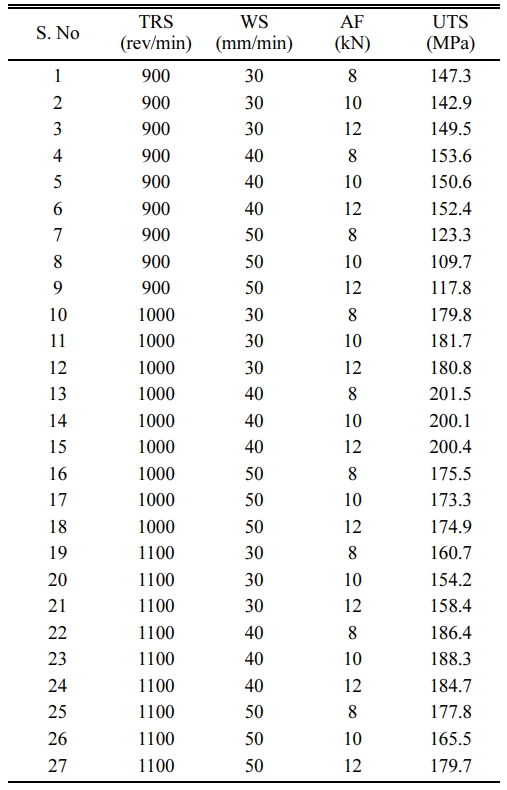
Trial welds were tried out to find the range of FSW process parameters that fetch good welding results. The parameters and their range were selected as: Tool rotation speed (TRS) 900-1100 rpm, Weld speed (WS) 30-50 mm/minute and Axial Force (AF) 8-12 kN. Butt joint configuration was selected to fabricate the FSW joints [26]. A non-consumable square tool, made of high carbon high chromium steel, was used to fabricate FSW joints in a vertical milling machine. The dimensions of the FSW tool are given in Fig. 1. Taguchi design is used to find the proper control factor settings. For the design of 3 parameters with each 3 levels, L27 orthogonal array is selected to carry out the experiments. The process parameters of FSW are shown in Table 2. The FSW machine and the weld specimen are shown in Fig. 2.
Ultimate Tensile Strength (UTS) Test
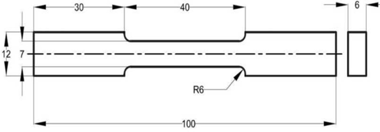
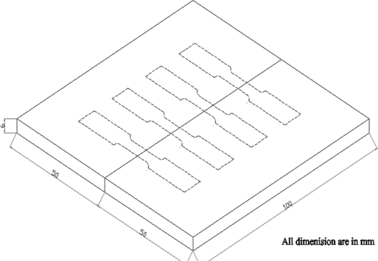
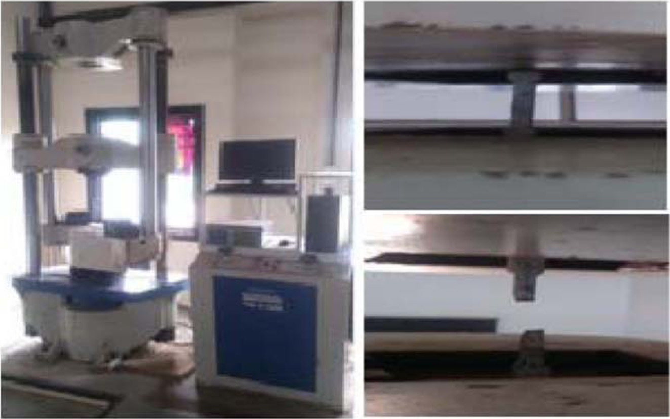
Tensile strength (TS) is one of the mechanical char- acteristics used to find the nature of FSW processed hybrid composites. The FSW joints was made based on Taguchi’s L27 orthogonal array design. The plates, after welding, were cut into the required size by wire EDM machine and then machined as per the ASTM E8 standard which is mentioned in Fig. 7. The TS values of 27 weld specimens were mentioned in Table 3. The schematic diagram of tensile specimen was shown in Fig. 6. The Tensile strength was analysed by universal testing machine which is mentioned in Fig. 8.
Taguchi design and ANOVA results
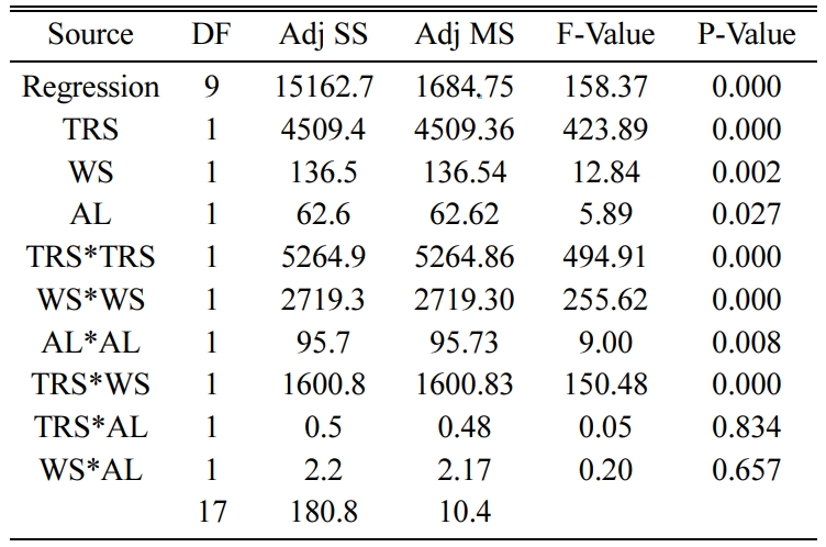
The adequacy of the experiments conducted is checked using ANOVA table using MINITAB V17 software shown in Table 4. ANOVA table shows the significance of each parameter involved in the process. The Probability value (or P-Value) for all parameters given shows values less than 4% or 0.05 thereby indicating that all three parameters of FSW are significantly influencing the TS value of the weld joint. TRS is the most significant parameter affecting the response followed by AF and WS. The R-Square and Adjusted R-Square values are greater than 90 % stating that strong relationship exists between the response and the predictor. The regression formula for the UTS is obtained and shown below:
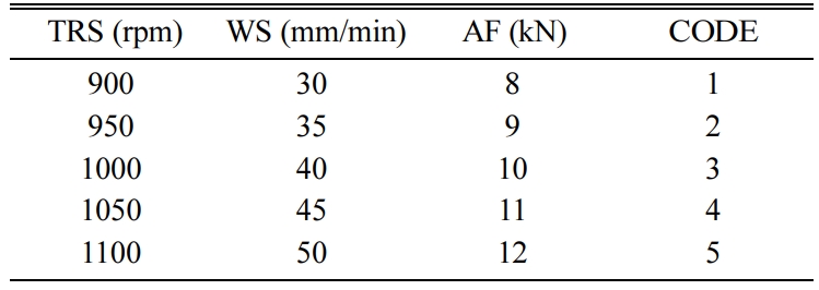
The levels of process parameters are increased from 3 to 5 considering the flexibility in the machine settings. The levels are decoded accordingly as shown in Table 6. The design space for the optimization is thus increased from 33 = 27 to 53 = 125.
Genetic Algorithm Methodology
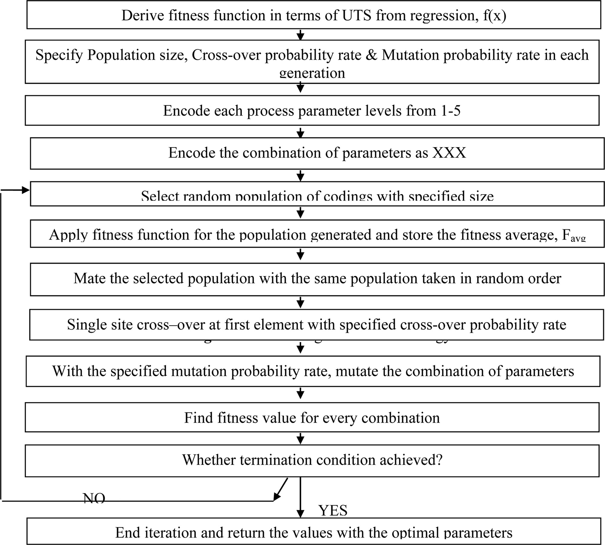
The methodology used in the study are summarized as flowchart in Fig. 9. The regression formula derived from the Taguchi design comprises the simple terms of process parameters. As the adequacy is safe, the fitness function for the GA analysis can be taken as the maximization of UTS in the design space. The design space selected in GA is similar to the levels used in Taguchi design but to find the best solution that maximizes the UTS requires a lot of time, man power, utilization of resources etc., in the conventional way. The best solution can be predicted through GA using the regression formula as GA explores the desired output within the space through iterations. Programming for the Genetic Algorithm is prepared in C package [27].
Genetic algorithm methodology.
The implementation of the genetic algorithm is essential to define the solution string or chromosome for the optimization problem. The bits or genes in the chromosome may be taken as binary or real integer number. In this work, TRS, AF and WS were considered to be the process parameters for the FSW process. Each of these variables is represented in real integer format. The length of the string is 3 in which every bit is used for the representation of TRS, WS and AF in sequence. The strings (111) and (999) represent the lower and upper limits of the process parameters. The coding for the FSW parameters is given in Table 8.
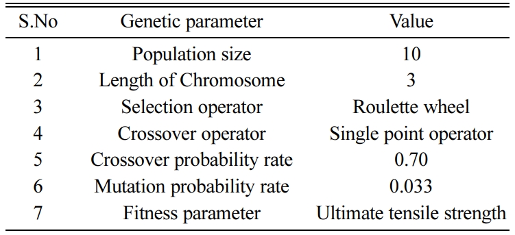
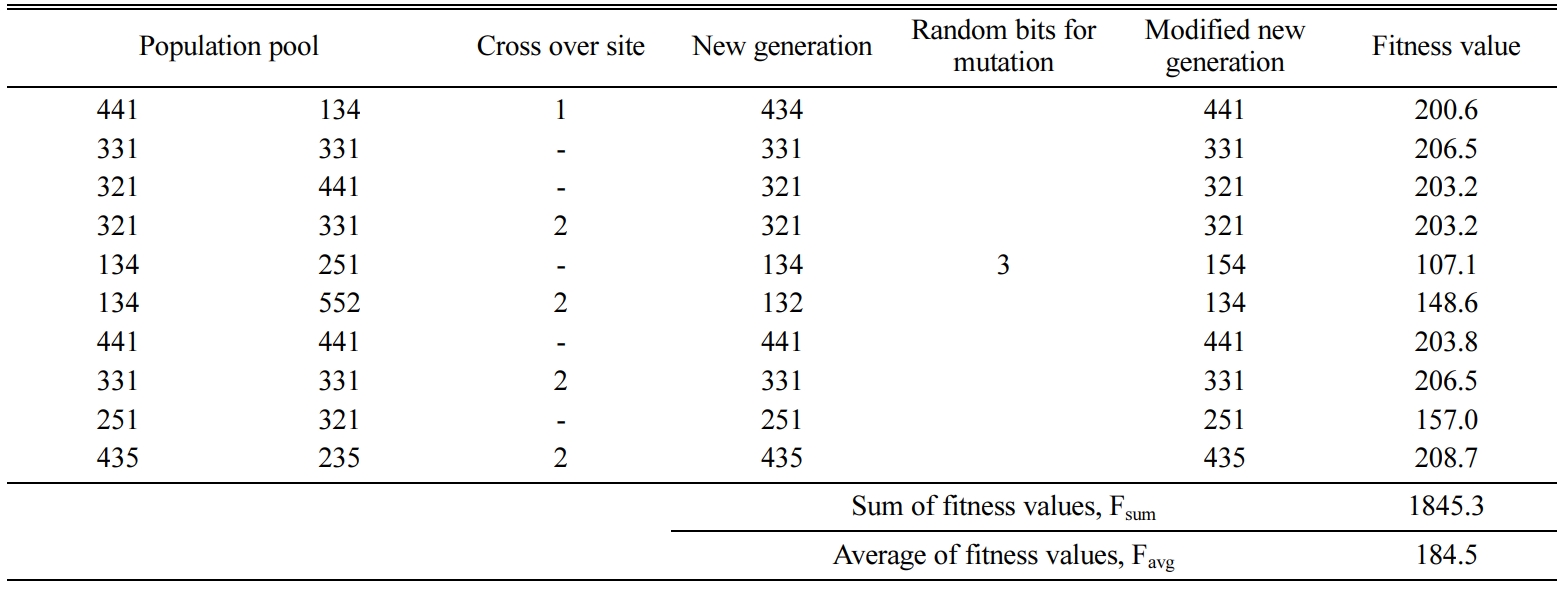
At the point of initialization, the solution space of a population lot is generated from the set of parameters mentioned above. The limit of the population lot is considered as 10 as shown in Table 10. Column 1 re- presents the string of the parameters. Columns 2, 3 and 4 represent the corresponding values of FSW process parameters. Column 5 shows the fitness value of the string derived from the empirical relation from Table 10. Columns 6, 7, 8, 9 and 10 represent the proportion (β), expected count (E), cumulative probability (C), random number (R) and string (S). The values for proportion (β) and Expected count (E) are tabulated from the following formulae:

The sum and average of the fitness values are also tabulated and saved as Fsum and Favg respectively.
Evolution
In GA, the fitness function is calculated for each string of chromosome in the population lot using the empirical relation. The fitness function is constructed from the empirical equation with the maximum R2 value as shown in Table 7. The fitness function taken for the genetic algorithm analysis was taken as follows:
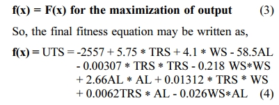
The population size, cross-over probability rate and Mutation probability rate are considered as shown in Table 10. Cross-over rate is selected to 0.70 to ensure that the better combination of parameters with good fitness value is retained to the next generation. In order to get the desired variability in the population, mutation rate is selected to 0.033 to change one bit in the population of 10.The levels are decoded accordingly as shown in Table 11.
Selection and Reproduction
Roulette wheel method of selecting the best parents for mating is used here for the cross-over phase. Random number is selected after the initial population evolution. Depending upon the space occupied by the random number, string number is decided.
Cross-over
Crossover is the mechanism used in GA for diversification of genes. The strings selected randomly in the population lot are crossed with the random number string. A single-point crossover is used in the analysis. The crossover probability is 0.70. For the population lot of 10 strings, cross-over of strings are programmed in 7 strings either at the end of first or second bits. The concept of crossover is explained below.
Before cross-over:String 1: 111; String 2: 555
After cross-over: (Cross-over site is 1)
New offstring: 155
After the cross-over at the end of the site 1 of parent 1, the string of parent 2 is copied and thus the new string for the offspring is obatined.
Mutation
Mutation is the selective modification of a randomly selected string in one bit. For every generation of population lots, the formula for the bits to be changed for mutation is derived from the following formula.

In this work, one bit is changed for the population lot of 10 strings. This is explained as below.
Before mutation: String 3: 333; String 6: 777
After cross-over: (Cross-over site is 2)
Offstring: 337
After mutation: (Mutation site 3)
New offspring: 339
This completes one iteration of the genetic algorithm and the best valued string is stored. The strings available at the end of previous iteration will be treated as the parents for the next consecutive iteration. This procedure is repeated for the number of iterations as specified by the user. Fig. 3 Fig. 4 Fig. 5 Table 5
|
Fig. 1 Stir casting setup. |
|
Fig. 2 FSW tool dimensions (All dimensions are in mm). |

|
Fig. 3 (a) Schematic diagram of the FSW Joint (b) Clamped test plates (c) FSW Experimental setup |
|
Fig. 4 Typical FSW plate. |
|
Fig. 5 Samples of FSW butt joint plates. |
|
Fig. 6 Dimension of tensile specimen. |
|
Fig. 7 Extraction of tensile specimen from FSW joints. |
|
Fig. 8 Universal testing machine. |
|
Fig. 9 Flowchart of Genetic Algorithm. |
The results of the first generation is shown in Table 11. The values for the codes 5,6 and 9 are observed less than the Favg.. These values have the less probability to get selected in the population pool while using Roulette wheel since the circumference of the wheel is linear with the expected count. Similarly, the values 1, 2, 3, 4, 7, 8 and 10 with expected count greater than Favg are likely to be selected in the population pool. The cumulative probability (C) is calculated from the expected count, E. Thus, the C value for the last row is 2.
Programming is done in such a way that 10 random numbers are generated and the corresponding parents are selected based on the intervals of cumulative probability in terms of string, S. It is observed that the parents in rows 2,3,5,7 and 9 are not selected; 1 are selected once; 4,6,8 and 10 are selected twice as tabulated. Correspondingly the new population pool is generated and are mated with the previous generation as shown in Table 11. It is also noted that any code providing high Fi value may also be neglected and vice versa thereby improving the Favg value for every generation progressively.
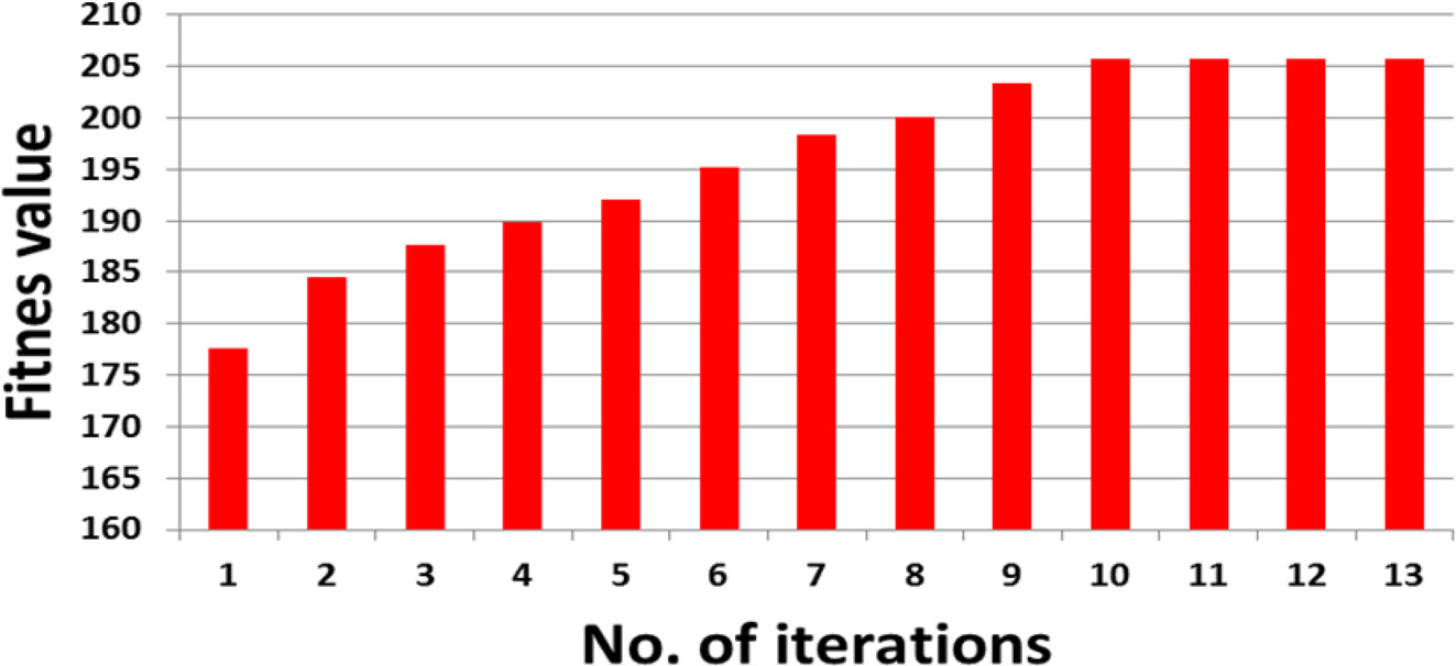
It is noted that the number of bits for mutation are calculated as 1 and changed in the first bit of 5th row.The bit selected for mutation is programmed such that the old codes are not selected in order to explore the undiscovered design space. It is observed that Favg value for the first iteration process has improved from 177.6 to 184.5. The same procedure is repeated until all the possible combinations are verified. It is observed that fitness value, Favg value increases and reaches the maximum value of 208.7 MPa as shown in the fitness evolution in Fig. 10.
Confirmation test
The final Favg value after the program run obtained is to be verified with the experimental results in order to validate the GA methodology. The corresponding parameters for the maximum UTS were obtained as code 442 indicating TRS – 1050 rpm; WS – 45 mm/min; AF – 10 kN. The code 442 is set with the vertical milling machine and five trial welds were carried out in order to eliminate any unwanted noise in the run. The average value of the trial welds results for the confirmation test obtained as 205.8 MPa with 1.22% error at 98% confidence level.
|
Fig. 10 Plot between fitness value vs Generations. |
The present study has made to optimize the tensile characteristics of AA6063-SiC-B4C using GA. Initially, AA6063-SiC-B4C hybrid composites were produced by stir casting technique. The stir casted hybrid com- posite was joined by FSW process by varying the tool rotation speed, weld speed and axial force and keeping the other key FSW parameters as constant. Taguchi L27 orthogonal array was followed to design the ex- periments. GA was used to optimize the maximum ultimate tensile strength of the hybrid composite through C programming. FSW of AMMC was used efficiently for joining of aluminium alloys. The tensile strength of the weldment of composites depends upon the FSW parameters and each parameter has its effect over the tensile strength. The maximum tensile strength was obtained 208.7 MPa with optimum FSW parameters such as TRS – 1050 rpm; AF – 10 kN and WS – 45 mm/min. The tensile strength of trial welds were 205.8 MPa which validated was with the optimized results by GA and proved that the experimental results are agreeable with 1.22% error at 98% confidence level.
- 1. K.K. Chawla, in “Composite materials: science and en- gineering” (Springer, 2012) p.1.
- 2. M.K. Surappa, Sadhana 28[1-2] (2003) 319-334.
-

- 3. S.V. Prasad and R. Asthana, Tribo. Let. 17[3] (2004) 445-453.
-

- 4. T. Miyajima, and Y. Iwai, Wear 255[1-6] (2003) 606-616.
-

- 5. C.S.Ramesh, R. Keshavamurthy, B. H. Channabasappa, and Abrar Ahmed, Mater. Sci. and Eng: A 502[1-2] (2009) 99-106.
-

- 6. S.P. Dwivedi, J. Mech. Sci. Tech. 28[1] (2014) 285-291.
-

- 7. K. Kalaiselvan, N. Murugan, and S. Parameswaran, Mater. Des. 32[7] (2011) 4004-4009.
-

- 8. P. Pugalenthi, M. Jayaraman, and V. Subburam, Materiali in tehnologije 53[1] (2019) 49-55.
- 9. V.C. Uvaraja, N. Natarajan, K. Sivakumar, S. Jegadheeshwaran, and S. Sudhakar, Indian J. Eng. Mater. Sci. 22[1] (2015) 51-61.
- 10. W.B. Lee, Y.M. Yeon, and S.B. Jung, Scripta. Materi. 49[5] (2003) 423-428.
-

- 11. Y. Lin, J. Hung, H. Chow, and A.C. Wang, J. Ceram. Process Res. 16[2] (2015) 249-257.
- 12. T. Sakthivel, G.S. Sengar and J. Mukhopadhyay, The Int. J. Ad. Manuf. Tech. 43[5-6] (2009) 468-473.
-

- 13. Y. Li, D. Sun, and W. Gong, Metals 9[8] (2019) 894.
-

- 14. U. Acharya, B.S. Roy, and S.C. Saha, Defen. Tech. 16[2] (2020) 381-391.
-

- 15. H. Park, H. Youn, J. Ryu, H. Son, H. Bang, I. Shon, and I. Oh, J. Ceram. Process Res. 13[6] (2012) 705-712.
- 16. C. Sharma, D.K. Dwivedi, and P. Kumar, Mater. Des. 36 (2012) 379-390.
-

- 17. S.O. Salih, N. Neate, H. Ou, and W. Sun, J. Mater. Process. Tech. 275 (2020) 116366.
-

- 18. A.M. Faradonbeh, M. Shamanian, H. Edris, M. Paidar, and Y. Bozkurt, J. Mater. Eng. Perf. 27[2] (2018) 835-846.
-

- 19. K.K. Ramachandran, N. Murugan, and S. Shashi Kumar, The Int. J. Ad. Manuf. Tech. 86[9-12] (2016) 2373-2392.
-

- 20. P. Jayaseelan, T.V. Christy, P.G. Rubesh, and R. Srinivasan, J. Comp. Theo. Nanoscience 16[2] (2019) 719-724.
-

- 21. W.H. Ho, J.T. Tsai, J.H. Chou, and J.B. Yue, IEEE Access 4 (2016) 2304-2313.
-

- 22. K. Elangovan and V. Balasubramanian, Mater. Des. 29[2] (2008) 362-373.
-

- 23. B.S. Babu, G. Chandramohan, C. Boopathi, T. Pridhar, and R. Srinivasan, J. Ceram. Process Res. 19[1] (2018) 69-74.
- 24. R. Whenish, B Sureshbabu, A Johnrajan, R Srinivasan, S N. kumar, A Kavitharan, C Pandikrishna and S Ragupathi, IOP Conf. Ser.: Mater. Sci. Eng. 988 (2020) 012063.
-

- 25. S. Lezhnev, D. Kuis, A. Volochko, A. Shegidevich, N. Svidunovich, and A. Naizabekov, J. Mater. Sci. Eng. 4[3] (2015) 3-5.
-

- 26. M. Dehghani, A. Amadeh, and S.A.A. Akbari Mousavi, Mater. Des. 49 (2013) 433-441.
-

- 27. K.K. Babu, K. Panneerselvam, P. Sathiya, A.N. Haq, S. Sundarrajan, P. Mastanaiah, and C.V.S. Murthy, Int. J. Adv. Manuf. Technol. 94 (2018) 3117-3129.
-

 This Article
-
2021; 22(1): 16-24
Published on Feb 28, 2021
- 10.36410/jcpr.2021.22.1.16
- Received on Mar 31, 2020
- Revised on Aug 23, 2020
- Accepted on Nov 11, 2020
 Services
Shared
 Correspondence to
- B. Suresh Babu
-
Assistant Professor, Department of Mechanical Engineering, Sri Krishna College of Technology, Coimbatore, Tamil Nadu, India
Tel : +91-9360556961 - E-mail: babusrptc@yahoo.co.in




 Copyright 2019 International Orgranization for Ceramic Processing. All rights reserved.