


- Estimation of ceramic material properties using specific rate of breakage determined from grinding tests of nepheline syenite
Serhan Haner*
Department of Industrial Design, Dinar Yerleşkesi, Afyon Kocatepe University, Cumhuriyet Mh. Kooperatif Cd. No:1, Dinar, Afyonkarahisar, Turkey
In this study, the effect of
specific rates of breakage of nefelinli siyenit, which is a magmatic,
feldspathic rock, on technological properties of ceramic bodies is examined.
The ceramic material properties considered in this study derived from the
application of non-destructive and destructive tests and include firing
shrinkage, water absorption, mercury porosimeter and firing strength, while the
specific rate of breakage (Si) determined from batch grinding
tests. In order to Si values, in the range of -63+53 μm
mono-size fraction was prepared. The nepheline syenite prepared in these
interval were ground with 1/4, 5/16, 3/8, 1/2 and 3/4 inches alloy steel balls
for different durations. The results indicate that the technological properties
of ceramic materials examined show very good correlation and can be used to
predict Si. Overall, it is deduced that multiple regression
analysis involving two independent variables is a reliable approach and can be
used to identify correlations between technological properties of ceramic
materials and specific rate of breakage values for nepheline syenite.
Keywords: Nepheline syenite, comminution, specific rate of breakage, ceramic materials, technological properties
Nepheline syenites are formed through a process that involves
both ordinary magmatic separation and volatile enrichment.
Nepheline syenites are alkali volcanic rocks that are
magmatic in origin, and that crystallize at a very advanced stage of magmatic
separation, while phonolites are their volcanic equivalents. Some of the
Canadian deposits are known to have metamorphosed during regional tectonic
events, while a metasomatic origin has been proposed for the older Livaara bed
in Finland [1, 2]. Typically associated with alkali or carbonatite
complexes, nepheline syenites have attracted considerable
worldwide interest in both economic and academic circles. Economic nepheline
syenite deposits that can be used in glass or ceramics are rare. Nepheline
syenite deposits usually have a high iron content. The largest reserves can be
found in Russia, Canada, Norway, Brazil, China and Turkey, all of which are
major global producers. In 2013, nepheline syenite with a total value of $59.3
million (491,000 tonnes) was imported worldwide [1, 3, 4]. In Turkey,
nepheline syenite is mined in the Buzlukdağı locality of the Akpınar district
of Kırşehir province, 12 km from the Kırşehir-Ankara road. The visible
nepheline syenite deposits in this field are 2,250 m long, 1,850 m wide and 450
m deep, and have properties suitable for the tile, vitrified tile, frit,
porcelain, glass, insulator, cement, insulation and electrode sectors.
Feldspathic materials have been the main melters used in
the ceramic sector for hundreds of years. In this highly
competitive environment, nepheline syenite plays an important
role. Due to its low melting point and melting ability, the use of nepheline
syenite in glass and ceramics has been analyzed in many studies conducted since
the early 1900s. Its main use is in the glass,
ceramic, filler, pigment, paint, coating and roofing granule
sectors. Its use for ceramic sanitaryware, tiles, electric porcelains,
tableware and glazes is based on its low firing temperatures and fast firing
programs [1].
Ball mills have been used in the ceramic sector and in
various other industries for close to 100 years, although the basic mechanisms
involved in breakage are yet to be fully understood. Early
theories of crushing were based on the simple empirical
relationship between energy input and size reduction ratio [5, 6].
As no attention was paid to the kinetics of breakage and the sub-processes
involved in grinding, the equations applied in these models led to design
problems during attempts to increase scales for commercial applications. Thus,
the process of grinding, which was not very efficient to begin with, became
even less so. To address these problems and to increase grinding efficiency,
models based on the kinetics of breakage in mills were developed [7, 8].
Through the advances in mathematical modeling and
simulation techniques, significant improvements have been
achieved, especially in the optimization of grinding circuits.
There have been several studies proposing different approaches to this issue,
including Herbst and Fuerstenau (1980), Austin et al. (1982), Kavetsky and
Whiten (1982), and Morrell and Man (1997) [9-12]. All of the proposed methods
involve laboratory or pilot-scale test data, a ball mill model based on the
equivalence of the amount of materials in each size fraction, and different
scale-enlargement processes. Methods based
on modeling and simulation consider the circuit as a whole, and as such, allow
the interaction between the ball mill
and other equipment to be identified. This makes it possible to calculate the
effect of any changes in the design or operation variables on flow tonnages and
particle size distributions.
One of the variable parameters affecting the grinding
process in a ball mill is the properties of the grinding balls, such as their
shape, size and specific weight. These are the main factors affecting the
particle size of the ground product, particle size distribution, grinding cost,
energy consumption, capacity and efficiency. To avoid problems during grinding,
the shape and size of the grinding ball should be appropriate for the area
being used.
Previous studies have examined the grinding behaviors
of various raw materials, while to the best of our knowledge there has yet to be
any study examining the effects of breakage rate parameters on the
technological parameters of ceramic materials [13-23]. Also, in some other
studies, the effect of nepheline syenite on ceramic materials is
examined [24-27]. The relationship between the
technical properties of rocks and their breakage parameters have been
ascertained in earlier studies, while the present study certainly offers
something new and original, identifying the potential correlation
between the specific rates of breakage of raw materials on one
hand, and firing shrinkage, water absorption, total porosity and firing
strength, on the other, as the most critical technological properties of
ceramic materials [28, 29].
The present experimental study made use of nepheline
syenite obtained from the Akpınar region of the province of Kırşehir, the
specific weight of which was found to be 2.44 g/cm3 [30]. The
nepheline syenite was characterized through determination of X-ray fluorescence
(XRF) using Spectro equipment, model X-Lab 2000; X-ray diffraction (XRD) using
Philips equipment, model X’Pert MPD, with radiation Cu-Kα (45 kV/40 mA).
Table 1 presents the chemical composition of nepheline syenite. The amounts of
Fe2O3 and MnO in the nepheline syenite were 0.29 and
0.01 mass-%, respectively. Nepheline syenite contains a very small amount of
TiO2.
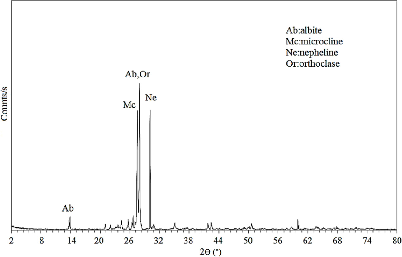
Fig. 1 shows the X-ray diffraction patterns of nepheline syenite.
Akpınar nepheline syenite consists of nepheline, orthoclase,
albite and microcline. The XRD results were confirmed by XRF.
First, the specific rate of breakage (Si)
of the nepheline syenite to a
mono-size fraction was identified, based on the kinetic model developed by
Austin, Klimpel and Luckie (1984). Accordingly, the specific rate of breakage
of nepheline syenite with a particle size range of -63+53 μm was calculated
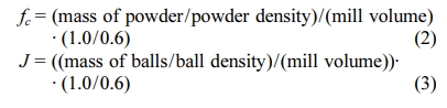
using Equation (1), while Eqs. (2), (3) and (4) were used, respectively, to calculate the
fractional powder filling (fc = 0.12), the fractional ball filling (J = 0.30)
and powder-ball loading ratio (U=1). The mill charge consisted of 1/4,
5/16, 3/8, 1/2 and 3/4 inches alloy steel balls with density ρb = 8.09
g/cm3. Experiments were performed in a laboratory-scale ball mill
with a volume of 2650 cm3 operating at a constant speed of N = 83-88
rpm (1.38-1.47 Hz), which is 75% of its critical speed.
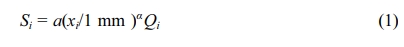
Qi are the correction factors. Qi=1
for smaller sizes and becomes small for large sizes. Xi, represents
the upper size (mm) of the range i. The value of α is a positive
number, normally in the range 0.5 to 1.5, which is characteristic of the
material (providing the test conditions are in the normal operating range) but
the value of a will vary with mill conditions [8].
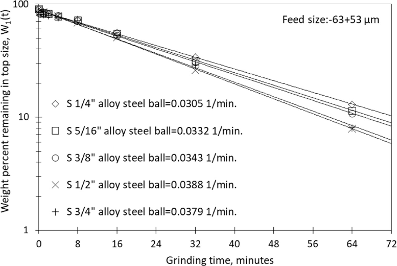
In kinetic experiments conducted in dry environments
under specified conditions, materials of a mono-size fraction have been ground
for linearly increasing grinding periods (0.5, 1, 2, 4, 8, 16, 32, and 64 min).
After each grinding period, semi-logarithmic graphs of the material fractions
remaining in the top particle size range were plotted against the grinding
periods, and the region in which the graph declines linearly is defined as the
first-order breakage region. The slope of the line in the first-order breakage
region indicates the specific rate of breakage of the material in that particle
size range.
The following stage involved the production of the bodies
of ceramic materials. Instead of the sodium feldspar found in the standard
recipe for ceramic bodies, grinding products from the 64th minute of the
kinetic grinding experiment were used. The goal was to investigate the
relationship between the specific rates of breakage (Si)
for a given size fraction and the technological properties of the newly developed
ceramic bodies, the formula of which is
given in Table 2.
The coding for the formulas of the ceramic materials is
given in Table 3.
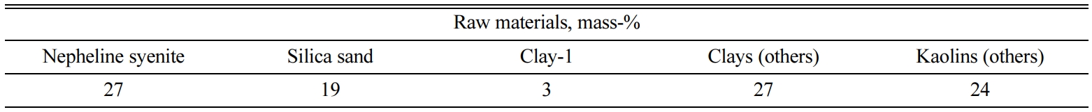
Following the formula in Table 2, the five different ceramic
material bodies noted in Table 3 were prepared. For the preparation
of the ceramic materials, first, the clay-1 and the silica sand that make up
the first phase mixture of the clay were placed in a mill containing porcelain
balls, following the formula, and ground for 7.5 h in an aqueous medium. The
nepheline syenite was then ground for 64 min (a product of kinetic model
experiments) and added to the raw materials, following the formula. In order to
obtain a homogeneous sludge, other clays and kaolins were added and mixed for 2
h at 750 rpm in a laboratory mixer. To ensure that clays were completely
dissolved, deflocculants (Na2SiO3), BaCO3
and water were added to the mixture in a controlled
manner. The preparation of the casting sludge in
accordance with the SM1, SM2, SM3, SM4 and SM5 formulas
was thus completed. A magnetic separator was used to
remove any magnetic impurities from the sludge, and finally, the casting sludge
was passed through a 150 μm sieve. To obtain the desired casting qualities,
deflocculant (Na2SiO3) was added to the sludge until the
liter weight, viscosity and thixotropy values were within the appropriate
ranges. A liter weight of the sludge was measured using a stainless steel
pycnometer (TQC, 100 mL), viscosity was measured using a
Brookfield viscometer, and thixotropy was measured
using a Torsion viscometer (Gallenkamp type). The
particle size measurements of the casting sludge were carried out using a laser
particle size analyzer (Malvern, Hydro 2000G). After being kept in the
laboratory environment for 24 h, the shaped samples were dried completely in an oven at a temperature of 105±2 oC.
Dried test rods and tablets were fired in a Riedhammer brand tunnel oven
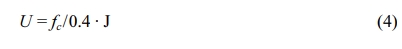
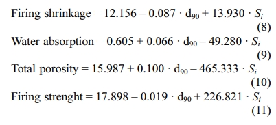
(fueled by natural gas, 110 m long), set at 1,200 oC. Eqs. (5),
(6) and (7) were used to calculate the firing shrinkage, firing strength and
water absorption values, respectively. The total porosity of the fired ceramic bodies was measured using a Poremaster 60 mercury porosimeter (Quantachrome
Corporation).
L1 is the
diagonal measurement when the tablet is green, L2 is the size
after drying and L3 is the size after firing in the oven.
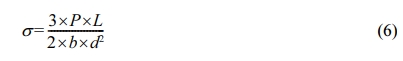
σ is the breaking strength (kg/cm2),
P is the breaking force (kg), L is the distance between supports
(cm), b is the the length of the broken surface of the sample (cm) and d
is the thickness of the broken region of the sample (cm).

Water absorption was measured following the TS 800 EN 997
standard. m0 is the first weight of the fired tablet, while m1
is the weight of the tablet after removal from the water absorption device.
|
Fig. 1 X-ray diffraction patterns of nepheline syenite |

|
Table 3 Grinding ball diameters of nepheline syenite and formula codes of ceramic bodies. |

Breakage
rate values of nepheline syenite
Nepheline syenite of a mono-size fraction was ground
for linearly increasing grinding periods using five different ball sizes. After
each grinding period, graphs of the material fractions remaining in the top
particle size range were plotted against the grinding periods. Fig.
2 reports the first-order breakage kinetics, and Table 4 reports the results.
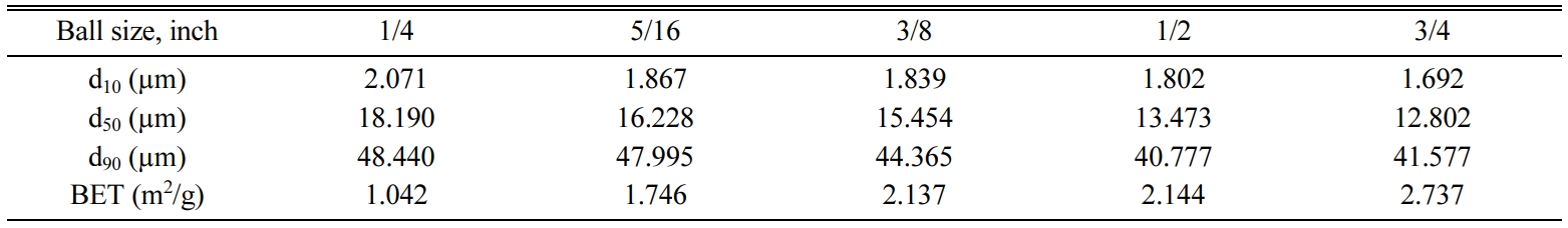
The d10, d50 and d90
values of the nepheline syenite, after being ground for 64 min, were measured
using a laser particle size analyzer (Malvern brand, Hydro 2000G). Multipoint
surface areas were measured using a Quantachrome Corporation's
Autosorb-6 BET (Brunauer, Emmet and Teller method) device.
The results are reported in Table 5.
Technological
properties of ceramic materials
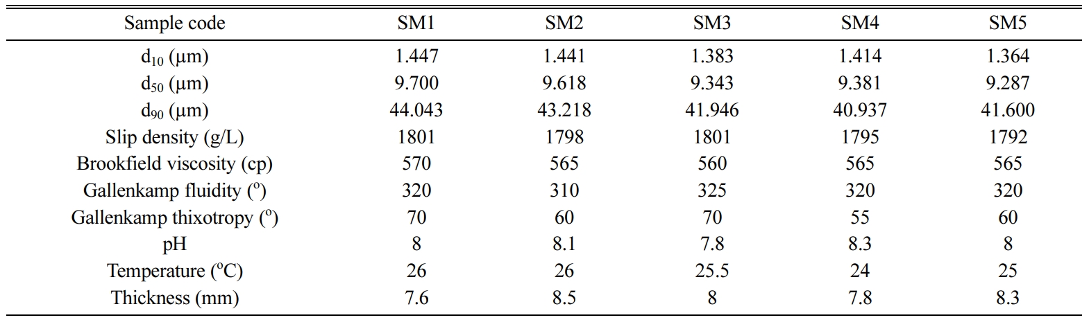
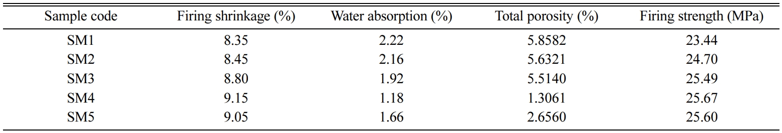
Table 6 reports the d10, d50, d90,
liter weight, viscosity and thixotropy values of the casting sludge of the
ceramic materials.
Table 7 presents the technological properties of the
ceramic materials fired in a Riedhammer-brand tunnel oven (fueled by natural
gas, 110 m long), set at 1,200 oC. Of the parameters affecting the
technological properties of the ceramic bodies, the body composition, the
casting properties and the firing regimes were kept constant in
all of the conducted tests. The only parameter that was varied was the particle
size distribution of the nepheline
syenite samples in the compositions (Table 5).
Table 7 reports the results of the ceramic bodies fired at
1,200 oC, in which it can be seen that tablets with larger
particle sizes recorded lower firing shrinkage and firing strength values, and
higher water absorption values. The firing shrinkage and
water absorption values under constant production conditions
serve as control parameters in the production of ceramic materials. The firing
shrinkage test is the most common approach to controlling the size of ceramic
materials. The technological
properties of ceramic materials may be related to their firing shrinkage
behaviors. The firing shrinkage of ceramic products is, in turn, affected by
many factors, including the particle size distributions of the raw materials
that make up the composition, their chemical and mineralogical properties and
ratios within the sludge, the firing regime of the oven (temperature and time)
and the amount of vitreous phase formed during firing. Firing shrinkage takes
place as the liquid phase that forms during firing surrounds solid particles
fills in the spaces within the body through capillary action [31, 32].
Evaluating Tables 5 and 7 in general terms, lower particle
sizes and lower firing temperatures result in greater firing shrinkage values
and lower water absorption values for ceramic bodies. The particles that make
up the composition were observed to be more reactive when the particle sizes
were small. Particle size is the main factor influencing the differences in the
firing shrinkage values of bodies with the same body composition that are fired
using the same oven regime. Bodies made of clays with fine particle sizes and
distributions are considered to have smaller pores, which are easier to remove
from the body during firing. This is supported by earlier studies in literature
[33-35]. The condensation and shrinkage caused by the liquid phase formation
during sintering reduces the number of pores as a result of the rearrangement
of particles through capillarity and surface tension effects [32, 36]. Smaller
particle sizes increase the reactivity of particles due to the increased
surface area, and as a result, the sintering process becomes more efficient
(Table 5). Moreover, sintering accelerates with the increase in the number of
contact points in cases with smaller particles [37]. Measurements conducted
using a mercury porosimeter show that total porosity declines with smaller
particle sizes (Table 7). The liquid phase that forms as the particle sizes
become smaller creates a highly condensed structure by supporting the reorganization
of particles and effective packaging. As porosity declines, the firing
shrinkage of the bodies increases. Previous studies in literature have revealed
that porosity and density values change depending on the amount of shrinkage
that bodies undergo [38, 39]. Moreover, a decline in water absorption is a
clear indicator of lower open porosity.
The strength of ceramic materials is defined as the amount
of energy required to break the atomic bonds in the material [40]. Tables 5 and
7 show that as particle sizes are decreased, the firing strength of the ceramic
bodies increases. At 1,200 oC, which is the industrial firing
temperature, the firing strength values for SM4 (d90 =
40.937 µm) and SM1 (d90 = 44.043 µm) were 25.67 MPa
and 23.44 MPa, respectively, offering a clear
indication of the influence of particle size. The rate of dissolution of
particles during sintering is inversely proportional to the particle size.
During sintering, smaller particles dissolve
and disappear, leaving behind only
larger particles, which is why strength is affected by the presence of larger
particles. Three different hypotheses
have been developed regarding the variables affecting the strength of ceramic bodies, being the mullite hypothesis,
the matrix reinforcement hypothesis and the strength through dissipative phase
hypothesis. The mullite hypothesis was first proposed by Zoellner (1908), and
is one of the oldest theories explaining the strength of ceramics. According to the mullite hypothesis, the greater the amount of mullite in the
structure, and the higher the strength. Mullite crystals have excellent
mechanical, creep resistant, thermal and chemical properties [41]. That said,
there have also been studies reporting that, contrary to the mullite
hypothesis, no parallel increase in strength values occurs as the amount of
mullite in the structure is increased [42-45]. According to the matrix
reinforcement hypothesis, the differences between the thermal expansion
coefficients of the matrix (the vitreous phase) and the dispersed particles
(such as quartz and alumina) or crystalline phases (such as mullite and cristobalite) generate strong compressive stresses. The thermal compressive
stress resulting from differences in
thermal expansion increase the
strength of ceramic bodies. Finally, according to the strength through
dissipative phase hypothesis, crystal phases in the vitreous phase of the
ceramic body improve strength by limiting the size of cracks [46]. It has been
reported in a previous study that strength is unaffected by the amount of
mullite phases, and that porosity, microstructural defects and larger particles
have a greater effect in this regard [47]. Tables 5 and 7 indicate that larger
particle sizes are associated with higher water absorption and lower firing
shrinkage values, and consequently, with lower strength values. One of the
leading parameters affecting the breaking strength of bodies is the porosity of their microstructures. Tables 5 and 7 show that pores and coarse
particles left in the microstructure facilitate the formation of cracks, and
thus have a negative effect on breaking strength. Lower porosity and higher
density are associated with higher strength in ceramic materials.
Theoretically, it would be possible to maximize breaking strength by eliminating
all of the pores in the microstructure [43, 45, 48-50]. The findings of both
previous studies and the present study reveal the breaking strength of ceramic
bodies to be affected by the number, shape and size of the pores in the
microstructure of the body. The total porosity and firing strength values
reported in Table 7 show that bodies with finer particle sizes have lower total
porosity values. At 1,200 oC, which is the industrial firing
temperature, the total porosity values for
SM4 (d90 = 40.937 µm) and SM1 (d90 = 44.043 µm) were
1.3061% and 5.8582%, respectively. This indicates larger particle sizes led to a decreased vitrification rate and an
increase in porosity, and as a result, firing strength declined. Stress is
concentrated in the pores in brittle ceramic materials. When the stress in the
pores reaches a critical value, the formation of cracks begins and progresses.
As there is no process to absorb energy throughout the deformation, the crack
propagation continues until a break occurs [51].
Correlation
between ceramic material properties, specific rate of breakage and particle
diameter
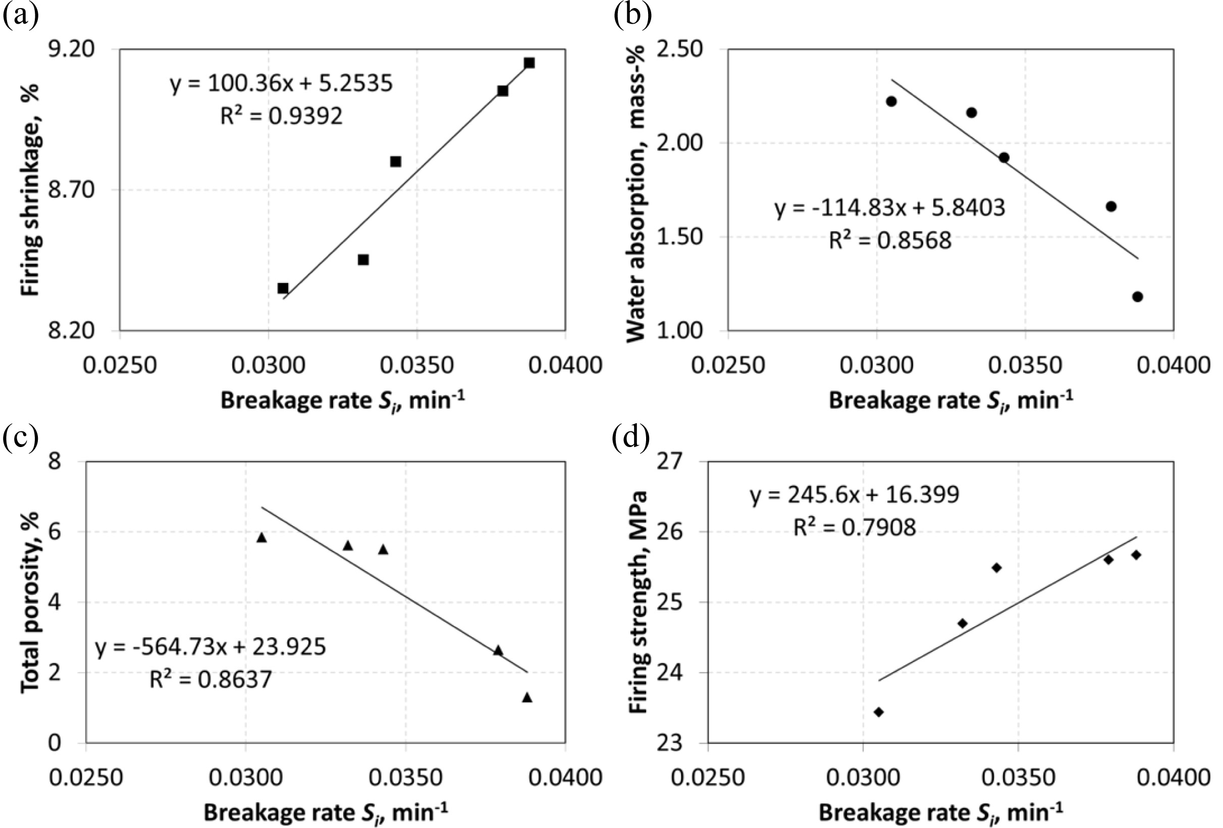
Using the concept of a linear curve and a simple
regression analysis in Excel, an estimating equation is developed between the Si
(Table 4) and d90 values (Table 5) of the nepheline syenite, and the
firing shrinkage, water absorption, total porosity and firing strength values
(Table 7) of the ceramic materials. The correlations between the Si
and d90 values on the one hand, and firing shrinkage, water
absorption, total porosity and firing strength on the other, are reported,
respectively, in Figs. 3 and 4.
Graphs (a), (b), (c) and (d) in Fig. 3 show a linear
relationship. It is seen that very strong correlation between Si
and firing shrinkage (R2=0.9392) and strong correlations
between Si and water absorption (R2=0.8568),
total porosity (R2=0.8637) ve firing strength
(R2=0.7908).
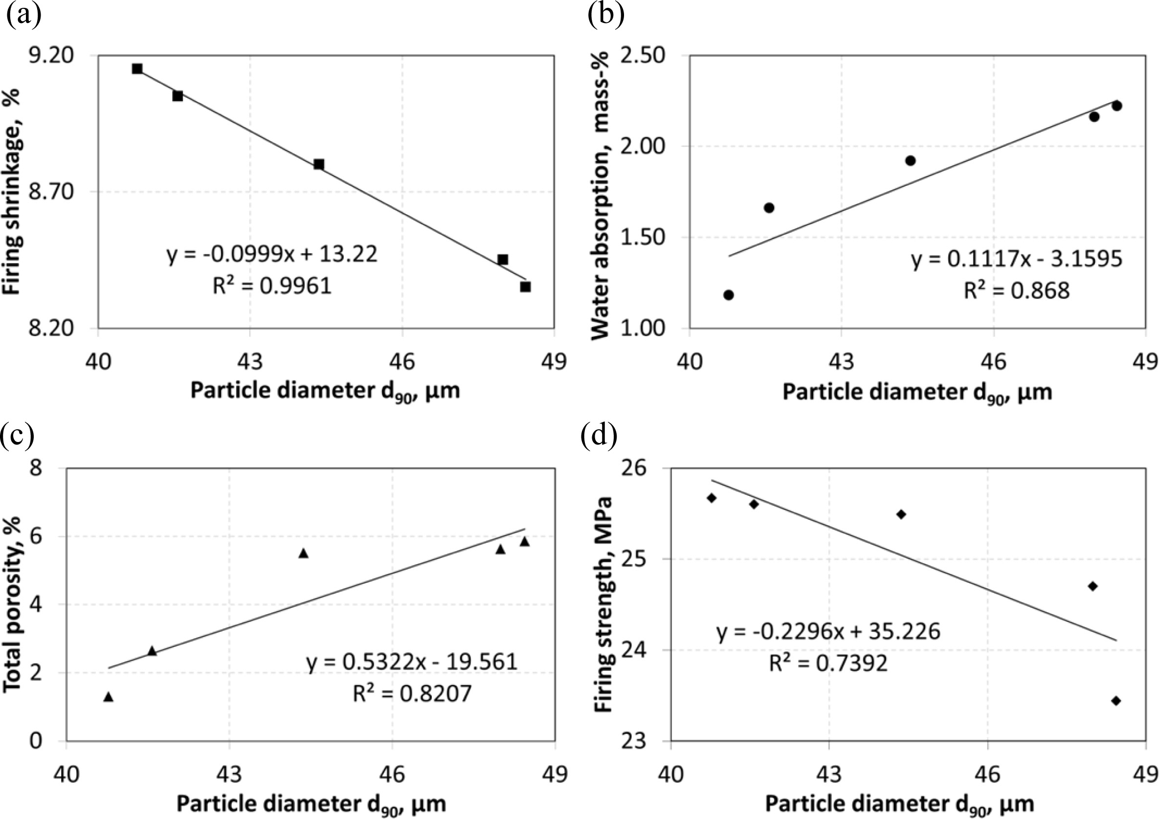
Graphs (a), (b), (c) and (d) in Fig. 4 show a linear
relationship. It is seen that very strong correlation between d90
and firing shrinkage (R2=0.9961) and strong correlations between d90
and water absorption (R2=0.8680), total
porosity (R2=0.8207) ve firing strength (R2=0.7392).
When materials are ground in the mill, the sizes of
products and the rate at which they are produced are an outcome of the
size-mass balance. Different rates of breakage are observed within the mill,
depending on the particle size. Si represents the specific
rate of breakage of the particles in a given size range “i”, and the unit of
the specific rate of breakage is time-1.
In other words, the Si value of materials classified in a
mono-size range is determined through a particle size analysis conducted at the
end of each grinding period. In order to control such technological properties
of ceramic materials as firing shrinkage, water absorption, total porosity and
firing strength, it is important to identify the particle sizes and particle
size distributions of the raw materials used. The particle size and the degree
of particle size distribution affect the reactivity of the components in the
composition during firing, and thus the number of of new phases (vitreous and
crystal) to be formed. Literature contains many studies on this topic [45,
52-54]. It is thus particle size that underlies the relationship between the
technological properties of ceramic materials and the specific rate of breakage
of the non-plastic materials used in ceramic materials
(Table 5). Looking at the relationships between the Si
and d90 values of non-plastic materials and firing shrinkage, water
absorption, total porosity and firing strength, which are among the
technological properties of ceramic materials (Fig. 3 and 4), coefficients of
determination (R2), are observed to vary between 0.9961 and 0.7392.
These results indicate strong or very strong relationships between the Si
and d90 values of the nepheline syenite used in ceramic materials
and the technological properties of ceramic bodies.
It is not always possible to explain a dependent variable
with a single independent variable. Variations in the technological properties
of ceramic materials are usually a result of multiple factors, and a large
number of variables may come together to produce an effect on another variable.
Furthermore, these variables may also have interactive effects on each other.
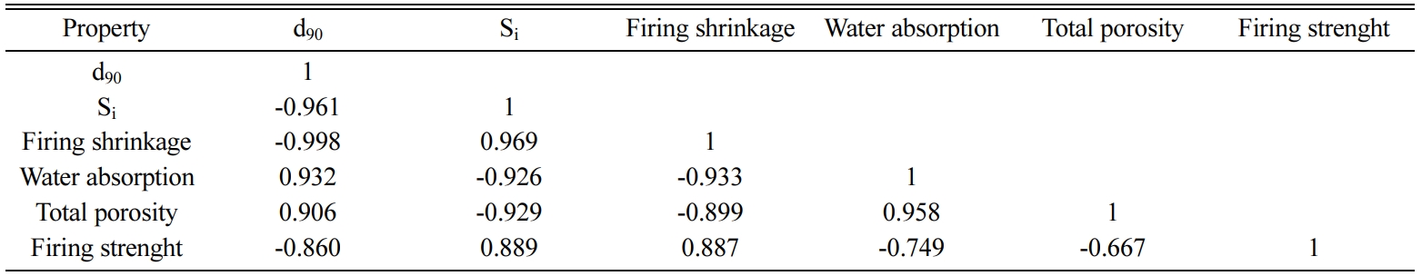
For this reason, in this study, to identify correlations between two
independent variables, which are Si values (Table 4) and d90
values (Table 5) of nepheline syenite, and firing shrinkage, water absorption,
total porosity and firing strenght of ceramic materials (Table
7) multiple regression analysis was performed by using
excel software. The correlation matrix for d90, Si,
firing shrinkage, water absorption, total porosity and firing strenght is shown
in Table 8.
According to the results of multiple regression analysis,
for each dependent variable the two independent variables with the highest correlation coefficients, as shown in
the correlation matrix, were used to perform the analysis. The firing strength
of ceramic materials may be influenced by variables other than firing
shrinkage, water absorption, porosity and particle size. Changes in firing
strength should be evaluated on the basis of mullite, matrix reinforcement and
strength through the dissipative phase hypotheses discussed in previous parts.
For the reasons explained here, it was expected that the correlation
coefficients between firing strength and the independent variables would be
slightly lower. Table 8 shows that high correlation coefficients were obtained
between firing strength and independent variables.
|
Fig. 2 First-order plots for balls with different diameters of
nepheline syenite |
|
Fig. 3 Correlations between breakage rate Si and (a) firing shrinkage, (b) water absorption, (c) total porosity and (d) firing strength. |
|
Fig. 4 Correlations between particle diameter d90 and (a) firing shrinkage, (b) water absorption, (c) total porosity and (d) firing strength. |
|
Table 4 Specific rates of breakage for balls with different diameters of nepheline syenite [30]. |

|
Table 5 The distributions of particle size and BET surface area of nepheline syenite which is used in ceramic composition. |
In the first stage of this study, 1/4, 5/16, 3/8, 1/2 and 3/4
inches alloy steel balls were used to identify changes in the specific rate of
breakage of the nepheline syenite in a particle size range of -63+53
μm, as a non-plastic raw material used as an alternative melter for ceramic
materials. All mill parameters aside from ball size were kept constant.
Products obtained after 64 minutes of grinding using these five
different ball sizes were added to the ceramic material composition as an
alternative to sodium feldspar. In the final stage, correlations
between specific rates of breakage of non-plastic raw material (Si)
and the technological properties (water absorption, firing shrinkage, total
porosity and firing strength) of ceramic materials were examined.
The Si values obtained from experiments
conducted using 1/4, 5/16, 3/8, 1/2 and 3/4 inches alloy steel balls showed
effective breaking until the ball size of 1/2 inches was reached, as the
original particles were quickly reduced to smaller sizes.
The d90 particle sizes of the sludge were
reduced with the addition of grinding products to the composition of the
ceramic materials, and this seemed to result in further condensation in the
fired bodies. As a result, the bodies’ firing shrinkage and condensation values
were higher, and water absorption and porosity values were lower, and higher
breaking strength values were obtained for bodies with smaller particle sizes.
The relationship between the specific rate of breakage
of nepheline syenite and the technological properties of the ceramic products
is related to the particle size in the melting phase in the structure of
ceramic materials.
The author would like to acknowledge the TUBITAK for
financially supporting this study (project name: TUBITAK-MAG-118M224).
- 1. J.E. Kogel, N.C. Trivedi, J.M. Barker, S.T. Krukowski, in “Industrial Minerals & Rocks, 7th Edition” (Society for Mining, Metallurgy, and Exploration, Inc., 2006) p.653-670.
- 2. N. Tuzcu, in “Petrografi-I (Magmatik Kayaçlar) (3.Baskı)” (Dokuz Eylül Üniversitesi Mühendislik-Mimarlık Fakültesi Basım Ünitesi, 1992) p. 222.
- 3. S. Haner and M. Demir, J. Geological Engineering 42[1] (2018) 107-120.
- 4. A.O. Tanner, in 2013 Minerals Yearbook (U.S. Geological Survey, 2015) p. 24.1-24.9.
- 5. F.C. Bond, in “The Third Theory of Comminution” (Transaction AIME (Mining), 1952) p. 484-494.
- 6. R.J. Charles, in “Energy-Size Reduction Relationship in Comminution” (Transaction SME/AIME, 1957) p. 80-88.
- 7. L.G. Austin, R. Bagga, and M. Çelik, Powder Technol. 28 (1981), 235-241.
-

- 8. L.G. Austin, R.R. Klimpel, and P.T. Luckie, in “Process Engineering of Size Reduction: Ball Milling” (American Institute of Mining Metallurgical and Petroleum Engineers Inc., 1984).
- 9. J.A. Herbst and D.W. Fuerstenau, Int. J. Min. Pro. 7[1] (1980) 1-31.
-
- 10. L.G. Austin, R.R. Klimpel, P.T. Luckie, and R.S.C. Rogers, in “Simulation of Grinding Circuits for Design Design and Installation of Communitaion Circuits” (AIME, 1982 p. 301-324.
- 11. A. Kavetsky and W.J. Whiten, in “Scale-up Relations for Industrial Ball Mills” (Proc. Australasian Institute of Mining and Metallurgy, 1982) p. 47-55.
- 12. S. Morrell and Y.T. Man, Miner. Eng. 10[12] (1997) 1311-1327.
-
- 13. F.H. Abd EL-Rahiem, EJMP&EP 5[2] (2005) 119-129.
- 14. Z. Bolin and Q. Haiyan, China Powder Science and Technology 17[3] (2011) 44-46,50.
- 15. D. Çuhadaroğlu, S. Samanlı, and S. Kizgut, Part. Part. Syst. Charact. 25 (2008) 465-473.
-
- 16. H. Hacıfazlıoğlu, Ö. Bilgin, S. Samanlı, B. Sungur, and İ. Toroğlu, J. Ore Dress. 9[18] 2007 25-31.
- 17. H. İpek, Y. Ucbaş, M. Yekeler, and Ç. Hoşten, Ceram. Int. 31 (2005) 1065-1071.
-
- 18. H. İpek, Miner. Eng. 19 (2006) 91-93.
-
- 19. N.S. Lameck and M.H. Moys, Miner. Eng. 19 (2006) 1377-1379.
-
- 20. W.E. Lee and Y. Iqbal, J. Eur. Ceram. Soc. 21 (2001) 2583-2586.
-
- 21. S. Houngaloune, K.S. Ariffin, H. Hussin, K. Watanabe, and V. Nhinxay, ASEAN J. Chem. Eng. 1[3] (2011) 144-153.
- 22. M. Yekeler, in Endüstriyel Hammaddeler Sempozyumu, April 1995, (TMMOB Mad.MO. İzm. Şb., 1995) p. 179-184.
- 23. H. Çelik, J. Ceram. Process. Res. 11 (2010) 622-626.
- 24. L. Esposito, A. Salem, A. Tucci, A. Gualtieri, and S.H. Jazayeri, Ceram. Int. 31 (2005) 233-240.
-
- 25. A. Salem, S.H. Jazayeri, E. Rastelli, and G. Timellini, J. Ceram. Process. Res. 10 (2009) 621-627.
- 26. A. Salem, S.H. Jazayeri, E. Rastelli, and G. Timellini, J. Ceram. Process. Res. 11 (2010) 74-81.
- 27. M.S. Elmaghraby, A.I.M. Ismail, D. Sadek Ghabrial, and Z.A. Abd El-Shakour, Silicon 12 (2020) 1125-1136.
-
- 28. A. Kılıç, A. Teymen, O. Özdemir, and C.D. Atiş, Iran J. Sci. Technol. Trans. Civ. Eng. 43 (2019) 171-178.
-
- 29. E. Petrakis and K. Komnitsas, Appl. Sci. 8 (2018) 1-17.
-
- 30. S. Haner, J. Min. Sci. 56 (2020) (in press).
- 31. E.M.H. Sallam and A.C.D. Chaklader, Ceram. Int. 11 (1985) 151-161.
-
- 32. A. Salem, S.H. Jazayeri, E. Rastelli, and G. Timellini, J. Mater. Process. Technol. 209 (2009) 1240-1246.
-
- 33. F.J.S. Arantes, D.F. Galesi, E. Quinteiro, and A. Boschi, in Proceedings of Qualicer 2002, March 2002, p. 139-142.
- 34. E.S. Vilches, in Proceedings of Qualicer 2002, March 2002, p. 57-83.
- 35. J.L. Amoros, M.J. Orts, J. Garcia-Ten, A. Gozalbo, and E. Sanchez, J. Eur. Ceram. Soc. 27 (2007) 2295–2301.
-
- 36. H. Baccour, M. Medhioub, F. Jamoussi, and T. Mhiri, Am. J. Appl. Sci. 5 (2008) 263-269.
-
- 37. E. Kivitz, B. Palm, J.G. Heinrich, J. Blumm, and G. Kolb, J. Eur. Ceram. Soc. 29 (2009) 2691-2696.
-
- 38. M.J. Orts, A. Escardino, J.L. Amoros, and F. Negre, Appl. Clay Sci. 8 (1998) 193-205.
-
- 39. V.G. Lee and T.H. Yeh, Mat. Sci. Eng. A 485 (2008) 5-13.
-
- 40. D.W. Richerson, in “Modern Ceramic Engineering: Properties, Processing and Use in Design” (Marcel Dekker, 1992) p. 399.
- 41. W.E. Lee and Y. Iqbal, J. Eur. Ceram. Soc. 21 (2001) 2583-2586.
-
- 42. Y. Kobayashi, O. Ohira, Y. Ohoshi, and E. Kato, J. Am. Ceram. Soc. 75 (1992) 1801-1806.
-
- 43. C. Leonelli, F. Bondioli, P. Veronesi, M. Romagnoli, T. Manfredini, G.C. Pellacani, and V. Cannillo, J. Eur. Ceram. Soc. 21 (2001) 785-793.
-
- 44. Ö.I. Ece and Z. Nakagawa, Ceram. Int. 28[2] (2002) 131-140.
-
- 45. G. Stathis, A. Ekonomakou, C.J. Stournaras, and C. Ftikosa, J. Eur. Ceram. Soc. 24 (2004) 2357-2366.
-
- 46. W.M. Carty and U. Senepati, J. Am. Ceram. Soc. 81 (1998) 3-20.
-
- 47. C. Zanelli, G. Dondi, G. Guarini, M. Raimondo, and I. Roncorati, Key Eng. Mater. 264 (2004) 1491-1494.
-
- 48. S.K. Das and K. Dana, Thermochim. Acta 406 (2003) 199-206.
-
- 49. C. Gil, M.C. Peiro, J.J. Gomez, L. Chiva, E. Cersueleo, and J.B. Carda, in Proceedings of Qualicer 2006, February 2006, p. 43-48.
- 50. L.C. Sivaldo, D. Hotza, and A.M. Segadaes, J. Mater. Sci. 43 (2008) 696-701.
-
- 51. W.F. Smith, in “Principles of Materials Science and Engineering” (McGraw-Hill Companies, 1995) p. 896.
- 52. S. Villegas-Palacio and D.R. Dinger, Am. Ceram. Soc. Bull. 75[7] (1996) 71-83.
- 53. E. Özel, D.Y. Tunçel, and M.K. Kara, J. Fac. Eng. Arch. Gazi Univ. 26[2] (2011) 299-306.
- 54. J.L. Amoros, M.J. Orts, S. Mestre, J. Garcia-Ten, and C. Feliu, J. Eur. Ceram. Soc. 30 (2010) 17-28.
-
 This Article
-
2020; 21(6): 736-744
Published on Dec 31, 2020
- 10.36410/jcpr.2020.21.6.736
- Received on Sep 9, 2020
- Revised on Nov 6, 2020
- Accepted on Nov 11, 2020
Services
- Abstract
introduction
materials and methods
results and discussion
conclusions
- Acknowledgements
- References
- Full Text PDF
Shared
Correspondence to
- Serhan Haner
-
Department of Industrial Design, Dinar Yerleşkesi, Afyon Kocatepe University, Cumhuriyet Mh. Kooperatif Cd. No:1, Dinar, Afyonkarahisar, Turkey
Tel : +905055794925 Fax: +02722183232 - E-mail: serhan.haner@gmail.com
Clean-Energy Research Institute(CRI), Hanyang University, 222, Wangsimni-ro, Seongdong-gu, Seoul, 04763, Korea
E-mail: jcpr@hanyang.ac.kr