


- Characterization of AA6061-ZrO2-C friction stir welded composite joints
R. Pandiyarajana,* and M. P. Prabakaranb
aAssistant Professor, Dept. of Mechanical, K.L.N College of Engineering -Pottapalayam, Tamil Nadu-63061, India
bAssistant Professor, Department of Mechanical Engineering, Erode Sengunthar Engineering College, Tamilnadu, India
In present work, investigation
of metallurgical and mechanical characterization of Friction Stir Welded MMC
material, the influence of micro structural properties on mechanical properties
using different heat inputs were conducted. These heat input generation depend
on the FSW process parameters such as Tool Rotational Speed, Welding Speed and
Axial Load. The FSW process parameters were set such as the tool rotational
speed in the range of 800 to 1000 rpm, axial load in the range of 4 to 6 kN and
a constant welding speed 50 mm/min to fabricate the FS welded specimen of MMC
materials. These process parameters play a major role in determining grain
growth, phase transformation and change in microstructure of different zones of
weldment like welded nugget zone (WNZ), thermo- mechanically affected zone
(TMAZ), heat affected zone (HAZ) and base metal (BM). Moreover, the effects of
changes in the microstructure help in improvements of mechanical properties
like tensile strength and hardness. The weld joints obtained with medium heat
input produced the fine grains and maximum tensile strength of 198 MPa and
hardness of 56 HRB at the tool rotational speed of 800 rpm, welding speed of 50
mm/min and axial load of 5 kN. The optical microscope (OM) and EDX analysis are
employed to identify the presence of the matrix, reinforcement particulates in
HMMCs and to confirm defect free welds attained at the WZ, TMAZ and HAZ during
the medium heat input condition.
Keywords: MMC, FSW, Metallurgical Characterization, Mechanical Characterization
Advanced lightweight engineering applications like
Aerospace, Automotive, Energy, Military, Electronics and Packaging industries
mostly make use of Friction Stir Welding process (FSW). The FSW is a low heat
input solid-state welding process invented by The Welding
Institute, the UK in 1991 [1]. The FSW process produces
plastic deformation in the material by generating an immense amount of heat.
The welding process of aluminium based MMC is very delicate due to aluminium
being difficult to weld than other metals. However, in the case of aluminium
based MMC, joints made by Fusion Welding processes possess many defects and are
not suitable to serve its purposes. Based on the previous research work carried
out on fusion welding on Aluminium Matrix Composites (AMCs), both
aluminium alloy matrix and hard ceramic reinforcing phase create
some problems during fusion welding like high thermal expansion, high thermal
conductivity, solidification shrinkage, incomplete mixing of parent and filler
materials, coarse grain structure at weld zone due to high heat input, high
solubility of gases in the molten state, presence of oxide inclusions [2-4]. To
this end, several investigations were carried on the FSW of Aluminum Metal
Matrix Composites (AMMCs) and its welding process parameters,
studying their microstructures and mechanical properties of these
joints.
Li et al. [5] investigated the microstructure and
mechanical properties of friction stir welded B4C / Al6061 joints,
and found the uniform distribution of B4C reinforcement in the
excited zone. Compared with base metal (BM) grain size, the weld nugget zone
(WNZ)’s grain size was smaller due to this nature and better mechanical
properties were observed in the WNZ. Shojaei et al. [6] studied the
microstructure and mechanical properties of FSW’ed aluminum based MMC with
bronze material joints, the improvement of mechanical properties from 10 to 15%
in FS welded joints. Also found the WNZ’s microstructure was completely
differed from BM’s microstructure. Guo et al. [7]
investigated the microstructure and mechanical properties
of dissimilar FSW’ed AA1100 / B4C MMC and AA6063 alloy joints, found
better improvements in mechanical properties such as tensile strength and
hardness. The maximum hardness and different grain sizes were observed in the
WNZ, also studied single – sided FSW of thin or dense AMMCs plates. Satish et
al. [8] studied and reported the effects of FSW process parameters of 5083
aluminum alloy joints, also known WNZ had achieved better
mechanical properties with fine grain size. Vijayavel and
Balasubramanian [9] investigated the effects on mechanical properties
for different tool pin profile designs and justified the square pin profile
which produced superior tensile strength compared with other design of profile
pins. Seyed et al. [12] studied the microstructure (OM, SEM and EDS) and
mechanical (microhardness and tensile strength) properties of
friction stir welded Mg-12Li-1Al
Alloy. The simultaneous improvement in grain structures
(19 μm to 73 μm) was to improve the hardness and tensile
strength properties up to 13%.
The survey revealed the most
common types of reinforcement materials such as TiC, Tib2, B4C,
Al2O3, SiC, Si3N4 etc and it also found
that the including usage of ZrO2 based reinforcement materials in
Aluminium MMC were limited. Based on the technical gaps noted from the
literature survey, the objectives have been framed for the present
investigation on enhancement of mechanical and metallurgical characterization of
Friction Stir Welded AA6061- ZrO2-C AMMC. The
present work consists, the investigation of metallurgical and
mechanical characterization of friction
stir welded MMC material, study of the influence of micro structural properties
on mechanical properties in the effect of three different heat inputs
generation such as low, medium and high of FS welded MMC materials. The range
of FSW process parameters were set as the follows: Tool Rotational Speed of 600
rpm, 800 rpm and 1,000 rpm, a constant Welding Travel Speed of 50 mm/min and
Axial Load levels of 4 kN, 5 kN and 6 kN to evaluate the optimum heat input
conditions and to obtain superior mechanical properties (tensile strength and
hardness) to produce a defect free joint. Stir Casting method was used to
fabricate the 92 wt% of AA6061, 6 wt% of ZrO2 and 2 wt% C of MMC
materials.
MMC
Materials preparation
A 92 wt% of AA6061 aluminum alloy was used in this
investigation along with 6 wt% of Zirconium Di-oxide (ZrO2) as the
primary reinforcement particulate and 2 wt% of Graphite (C) as
the secondary reinforcement particulate, the primary
reinforcement particulate of ZrO2 is more sought after in the
multi-industrial and technological applications due to its low co-efficient thermal
expansion, low cost and high thermal conductivity [10], also
it possess hard refractory ceramic quality and better
compatibility with aluminum alloys. For example, ZrO2
has a thermal conductivity of 175 W/mK which is less than the 250 W/mK for SiC.
In this regard, the materialistic stability of ZrO2 is better
because it is more heat resistant than SiC. In addition, ZrO2
possesses hard refractory ceramic compatibility
with Al alloy. The secondary reinforcement particulate,
Graphite (C) has much flexibility (though not elastic), valuable electric as
well as thermal conductivity and high wear resistance. The specification
of reinforcement particulates is of 99.5% purity, 11-39 µm particulate size of
ZrO2 and 98% purity, a 325 mesh size for C to fabricated the MMC
materials.
To fabricate the aluminum metal matrix composite (AMMC)
by stir casting method, AA6061 was chopped into smaller
pieces and placed inside the induction furnace crucible. It was melted at a
furnace temperature of 850 oC. In this molten stage the
primary and secondary reinforcement particulates were
gradually mixed with AA6061 matrix before mixing the particulates it were preheated
to 350 oC for removed moisture contents. The
semi-liquid composition was stirred well for the time duration of 10 minutes at
constant speed of 450 rpm to obtain a homogeneous distribution of particulates
in the mixture [11]. Then the stirred semi-liquid composition
material was poured into a rectangular mold to cast the required number of work
pieces in the size of 100 × 50 × 6 mm.
Friction
stir welding of MMCs
The stir cast MMC plates were successfully welded by
friction stir welding (FSW) process by using square profile tool as shown in
Fig. 1. There are three main process parameters that highly influence the
quality of FS welded joints in MMC such as tool rotational speed,
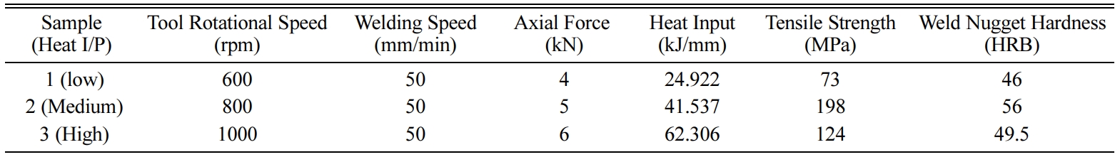
welding speed and axial load [12-14]. The process parameters and their
respective levels are presented in Table 1.
Heat
input calculation
The square pin profile design tool was used to fabricate
the FS welded MMC material to cause the plastic deformation in the stirred zone
by producing an immense amount of heat during at FSW process. As a result, the
micro structures’ changes were observed in the weldments. Eqs. (1) and (2) were
used to calculate the amount of total torque and heat input values, and Eq. (3)
were employed for finding the average heat input under the tool shoulder pin
[15]. The total frictional torque and heat average input were developed by the
tool rotational speed (rpm) are given by
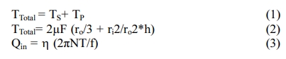
where, TS = Torque
generated by the tool shoulder (in N-m), TP = Torque generated by
the tool pin (in N-m), µ = Co-efficient of Friction, F = Applied Axial Force
(in N), ri = Radius of the tool shoulder (in m), ro =
Radius of the tool pin (in m), h = height of the tool pin (in m), TTotal=
Total torque (in N-m), h =
Efficiency, N = Tool rotational speed (in rpm), f = welding speed (in mm/min)
and Qin= Average heat input (in kJ/mm). Table 1 presents the amount
of heat generated by the FSW tool for different welding conditions, also each
welding conditions and corresponding amount of heat generations were influenced
in grain growth, phase transformation in the microstructure and hardness of
welded and heat-affected zones. In this study, three levels of
heat inputs were considered to better understand the
effects of heat input in metallurgical characterization. From Table
1, they can be seen as, 24.922 kJ/mm as low, 41.537 kJ/mm as medium and 63.306
kJ/mm as high level of heat inputs generated by FSW tool.
Metallurgical
and mechanical properties
The metallurgical study was carried out along various
zones across the cross sections of FS welded specimens by using of a
metallurgical microscope in different magnification ranges. The chemical
composition of the AMMC’s samples was detected by using of SEM with EDX
spectrum analysis. The FS welded MMC specimen in the size
of 15 mm ´ 15
mm ´ 10 mm
was cut and polished with emery sheets, having the grits in the range
of 220 to 1,200. The specimen surface was further polished
using a diamond polishing disc of 6 µm, 3 µm, and 0.5 µm. Further polishing was
made again by applying the alumina solution to give a glossy finish to the
specimen. Finally, the specimen was etched with the help of Keller’s agent. The
specimen was well prepared to observe the Base Composite (BC), Heat Affected
Zone (HAZ), Thermo Mechanically Affected Zone (TMAZ) and Welded Nugget Zone
(WAZ) under different magnification levels (100X / 100 µm,
100X / 50 µm, 200X / 50 µm) on an optical microscope
and EDX analysis (Zhang et al., 2015; Vijay et al., 2010).
The FSW joints are tested for their mechanical properties
as per ASTM standards E08 M-04 for the tensile test and E10 for the hardness
test. The tensile test characterizes the elastic-plastic behaviour of a
material by applying a uniaxial tensile load. All the tensile tests are
conducted in a displacement control mode at a rate of 0.1 mm/min. The localized
strain variations in the tensile samples were measured using an extensometer,
it is used to measure the change in length of the FS welded MMC. Engineering
stress-strain relation is calculated for each specimen.
The hardness test specimen samples were made in
rectangular shape using the wire-cut EDM process, as per the specification
mentioned earlier (15 mm ´ 15
mm ´ 10 mm).
These samples were placed on the hardness testing machine and subjected to an
axial load of 500 g using a ball indenter for a dwelling period of 10 s. The
spherical indentation induced by the 1/16’ diameter indenter was measured on
various locations in the sample surface. The micro hardness survey is made at
different positions in various zones of welded joints.
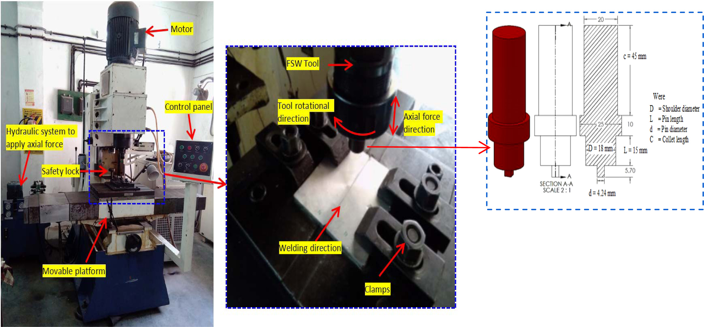
|
Fig. 1 Experimental setup of FSW. |
Microstructure
friction stir welded MMCs
The Scanning Electron Micrograph (SEM) image of 92% Wt% of
AA6061, 6 Wt% of ZrO2 and 2 Wt% of C particulate stir cast aluminum
matrix composite materials is shown in Fig. 2. It clearly shows the
uniform dispersion of reinforcement
particulate in stir cast aluminum AA6061, ZrO2 and C reinforced
composite materials. It is noticed that the particulate
agglomeration was reduced considerably. It makes sure that proper
stirring was employed during fabrication of MMC. The random orientation of
particulates provides uniform strength to cast material in all directions.
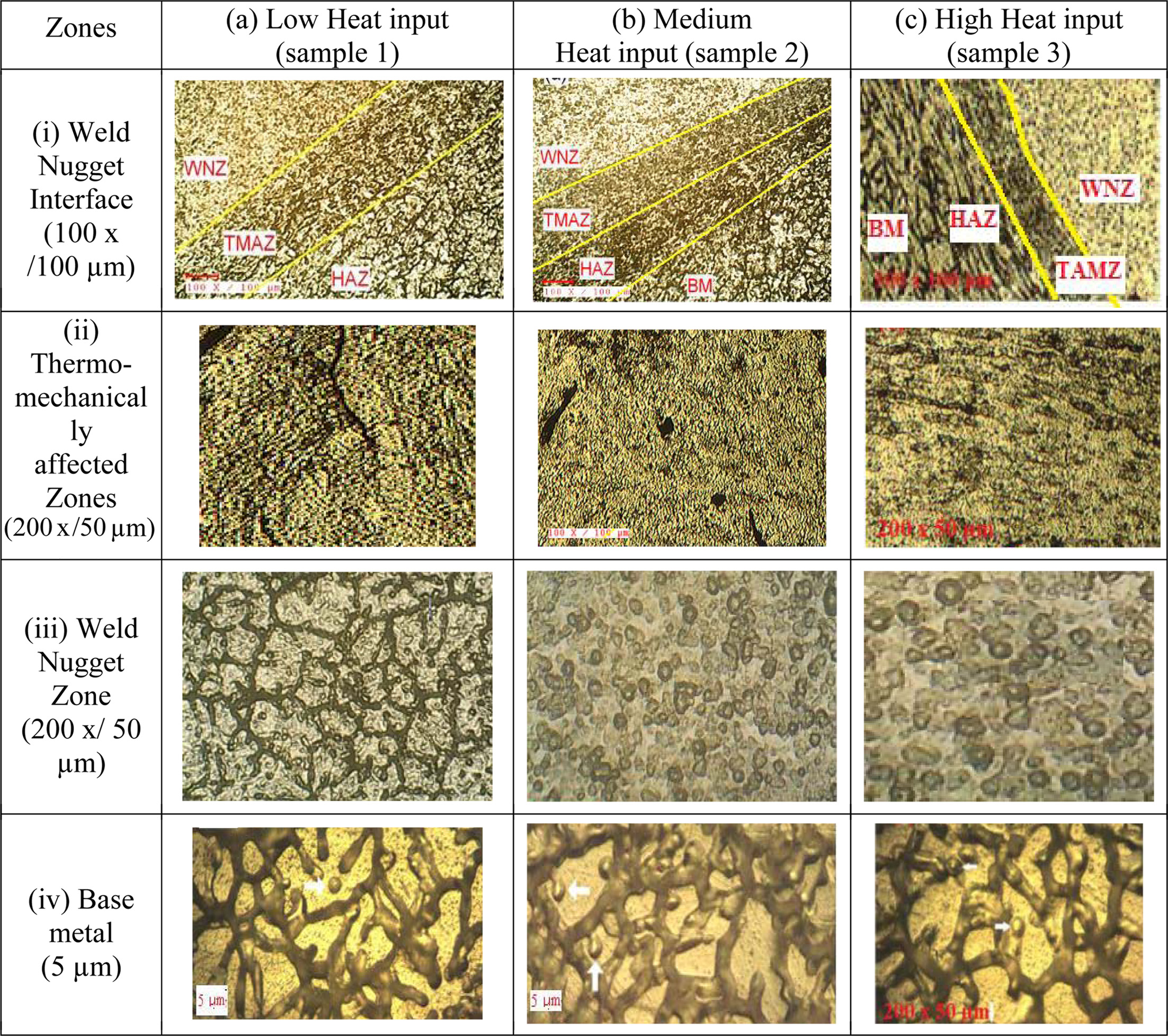
Fig. 3 shows that the optical microscopy images of
friction stir welded joints with different zones like base metal (BM),
thermos-mechanically affected zone (TMAZ), weld nugget zone (WNZ) and heat affected
zone (HAZ), also represents the size, shape and distribution
of the grain structure of reinforced particulates. Compared
all samples, the sample 1 weld zone had poor penetration and columnar dendrites
along with pores and it causing lower tensile strength. Also it has more
recrystallized structure in the TMAZ surface. Sample 2 & 3 obviously shows
that the cluster and even distribution of C particulates in the FSW’ed WNZ
surface that occurred throughout the matrix, similarly ZrO2
particulates were also evenly distributed. The FSW’ed MMCs of WNZs were
presenting columnar dendrites towards the welding direction, and the TMAZs were
found that the distribution of particles across the matrix was very fine and
uniform. But some amount of coarsening grains was observed in the friction stir
welded TMAZ surfaces of samples 1 & 2. Compared with sample 1, samples 2
& 3 ensuing improved mechanical and metallurgical properties of the welded
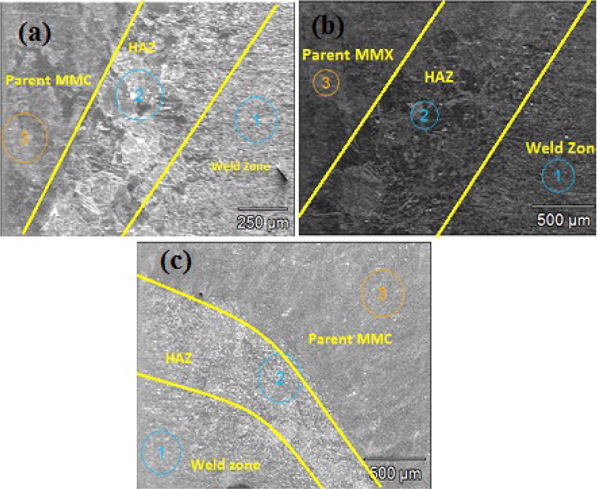
joints. The SEM with EDX spectrum analysis clearly shows the presents of other
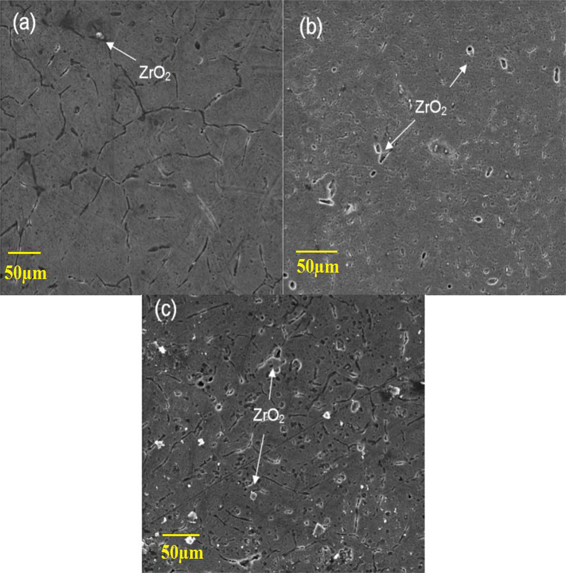
elements like Al, Zr, SiC, Mg, C, etc. Fig. 4(a-c) shows the SEM image of the
weld nugget interface zone and also shows the matrix and reinforcement
particulates in friction stir welded MMC and highlights the defect-free joints
of the cross weld. The SEM analysis of FS welded MMC
illustrates the other weld zone like WNZ, TMAZ, HAZ and BM. As observed, in
comparison to BM, the stir zone produces finer grain structure.
The matrix of this zone exhibits a fine grain size and has low segregation.
The grain structure is evenly dispersed in
this case when compared to Low heat input and High heat input conditions.
Furthermore, as observed in section
(ii) of Fig. 3, the thermo mechanically
affected zones of the matrix under Low heat input and High heat input conditions
are very much affected by the process parameters, thereby resulting in uneven
particulate dispersion. The composite matrix under the Medium Heat input
condition has better reinforcement grain
structure dispersion and fewer particulate dislocations. Section (iii) of Fig. 3 compares the Weld nugget
zone of the composite matrix under Low, Medium and High heat inputs. Here the Medium heat input zone is
observed to have better phase
dispersion between the base metal matrix and particulate reinforcements. Section
(iv) compares the base metal under similar conditions as above, therefore there
are no significant differences observed in cases of heat input.
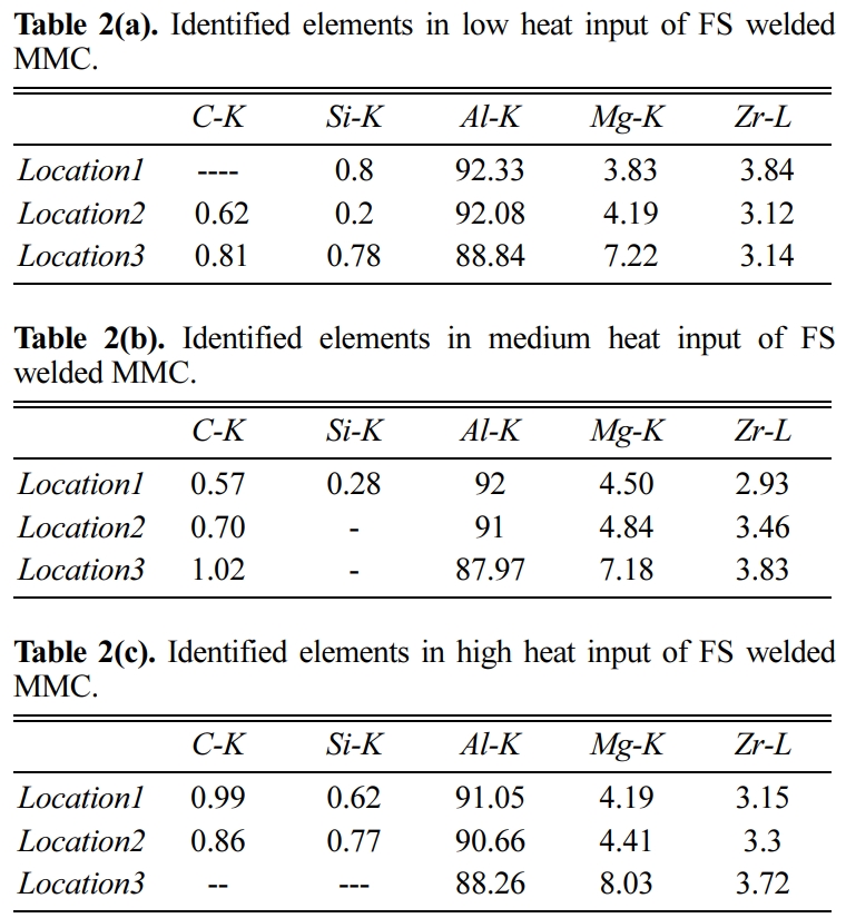
Chemical
composition
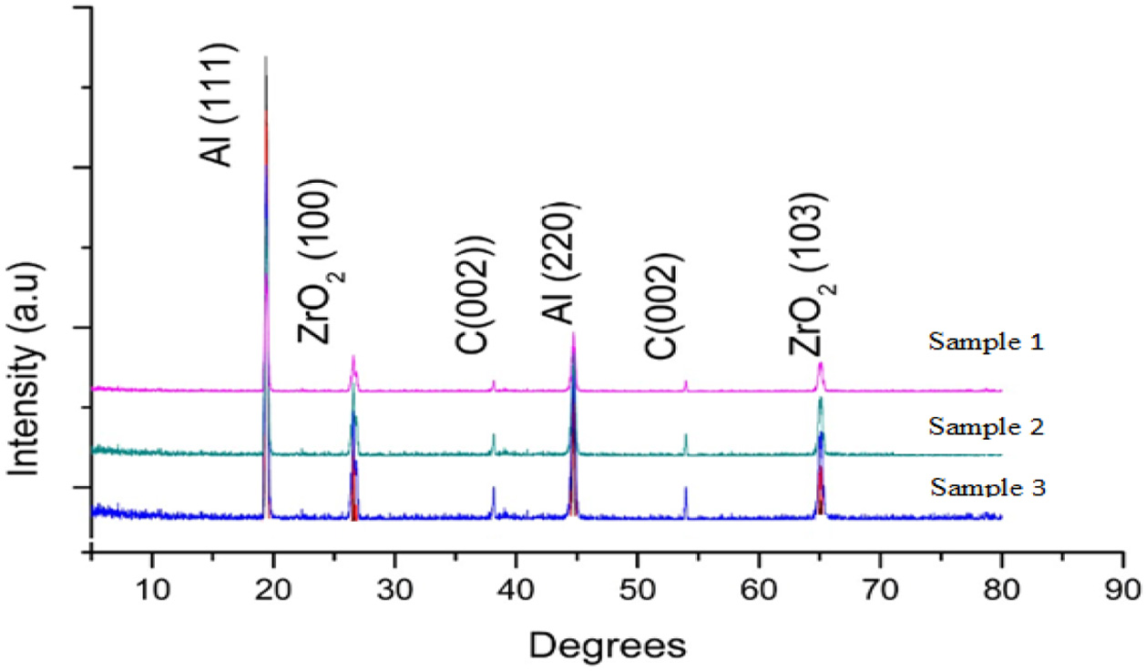
The chemical composition of the FSW’ed MMCs was measured
in the WNZs, and it presented the amount of alloying elements. Fig. 5 shows the
XRD analysis of FS welded AMMC with different heat input conditions like low,
medium and high. It also shows the presence of reinforcement particulates in FS
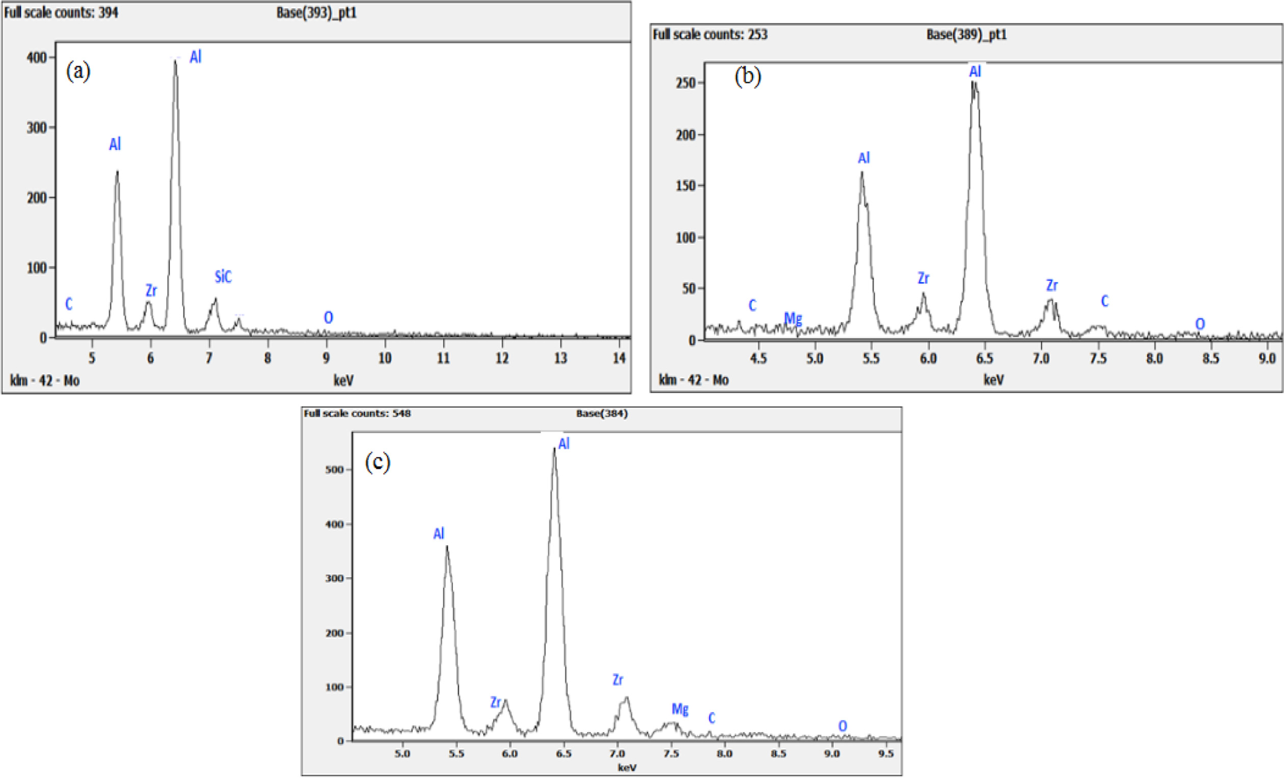
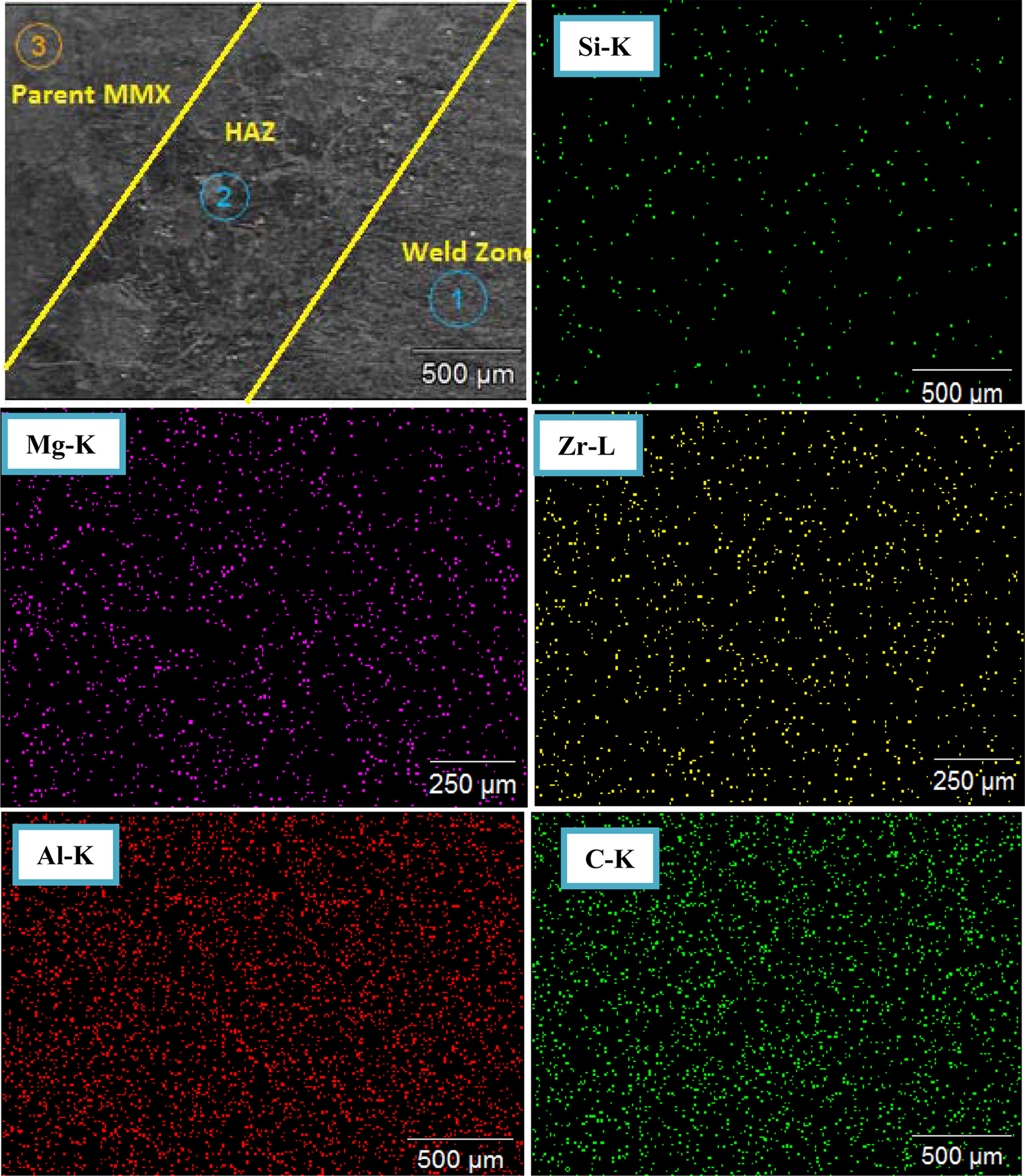
welded AMMCs materials. Fig. 6(a-c) shows the spectrum analysis of three
samples, and the presence of matrix and oxides can also be noticed. The zones
are marked in SEM image Fig. 6(a-c) at lactation 1, 2 and 3. Table 2(a-c) shows
the presence of elements in FS welded MMC at three different weld zones. The
EDS analysis clearly shows the present alloying elements such as Al, Zr, Si, C,
Mg, etc. in the MMCs welded zones. It has proven the uniform distribution of
matrix and uniform micro structure of FSW’ed zones. Fig. 7(a) shows that the
matrix elements of sample 1, and few amount of matrix were present in uneven
distribution (uneven mixing) due to insufficient heat input, having poorer
mechanical properties. But sample 2 & 3 shows that the uniform distribution
of matrix (even mixing) because of sufficient heat input, and it has improved
mechanical and metallurgical properties. The identified alloying elements of FS
weld MMCs were recorded in Table 3, Fig. 7(b-f) were showed friction stir
welded MMCs EDAX element mapping.
Mechanical
properties
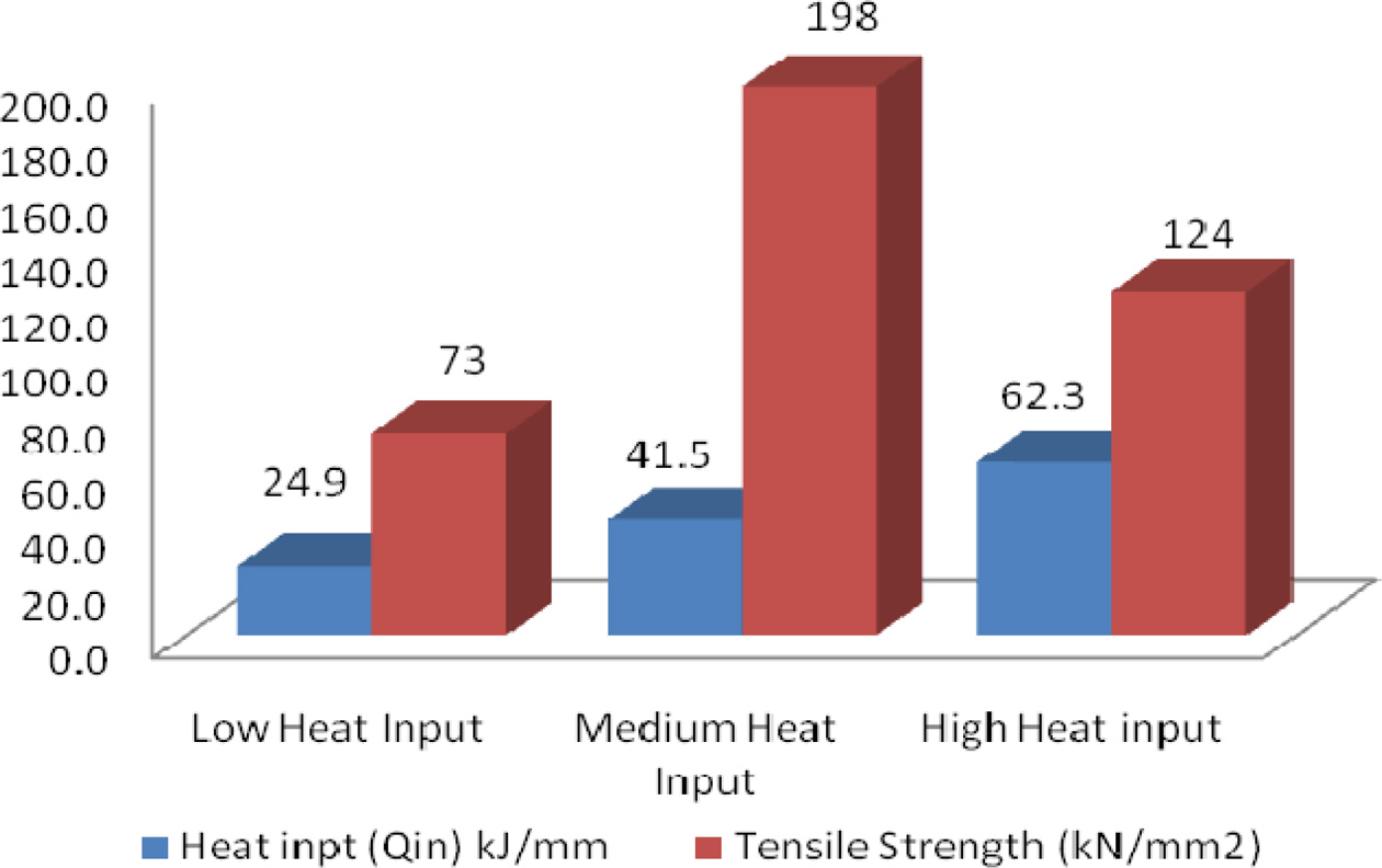
The mechanical properties such as Tensile Strength and
Hardness were measured after FSW’ed MMCs samples. By comparing three samples,
the sample 1 resulting lower tensile strength comparing with other two samples
(sample 2 & 3) due to insufficient heat input and uneven distribution of
matrix. Sample 2 & 3 ensuing higher tensile strength because of fine micro
structure and even distribution of matrix. These are all shown in Fig. 8.
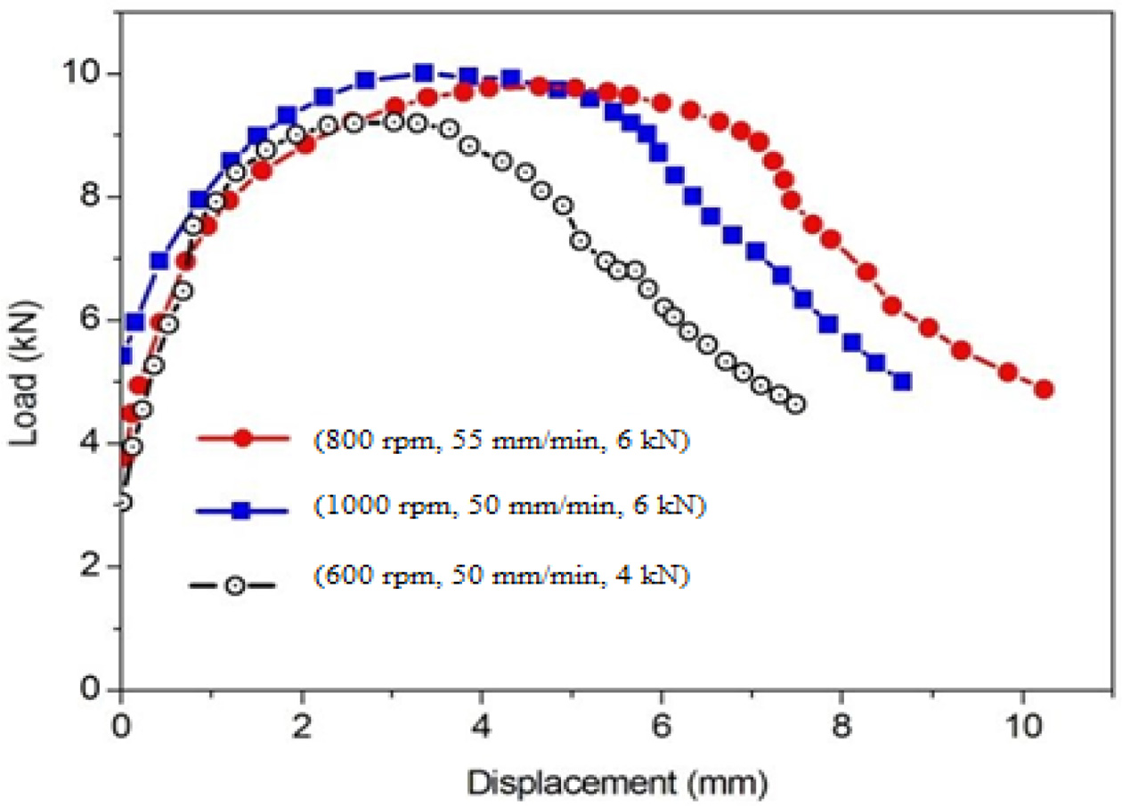
The significant contribution of reinforcement in the MMC
can be analyzed from Fig. 9. It is noticed that the variation in load-bearing
capacity of FS welded MMC is decreased by increasing the
heat input generation during FSW process. The maximum
breaking load of FS welded MMC is improved by lowering of heat generation to
the intermediate (Medium) conditions. Similarly the maximum displacement and
displacement at the breaking load of FS welded MMC is reduced by
increasing of heat generation and dispersion of reinforcement
due to stirring action of the FSW process. Due to
ceramic particulate reinforcement, it loses its strength rapidly during plastic
deformation.
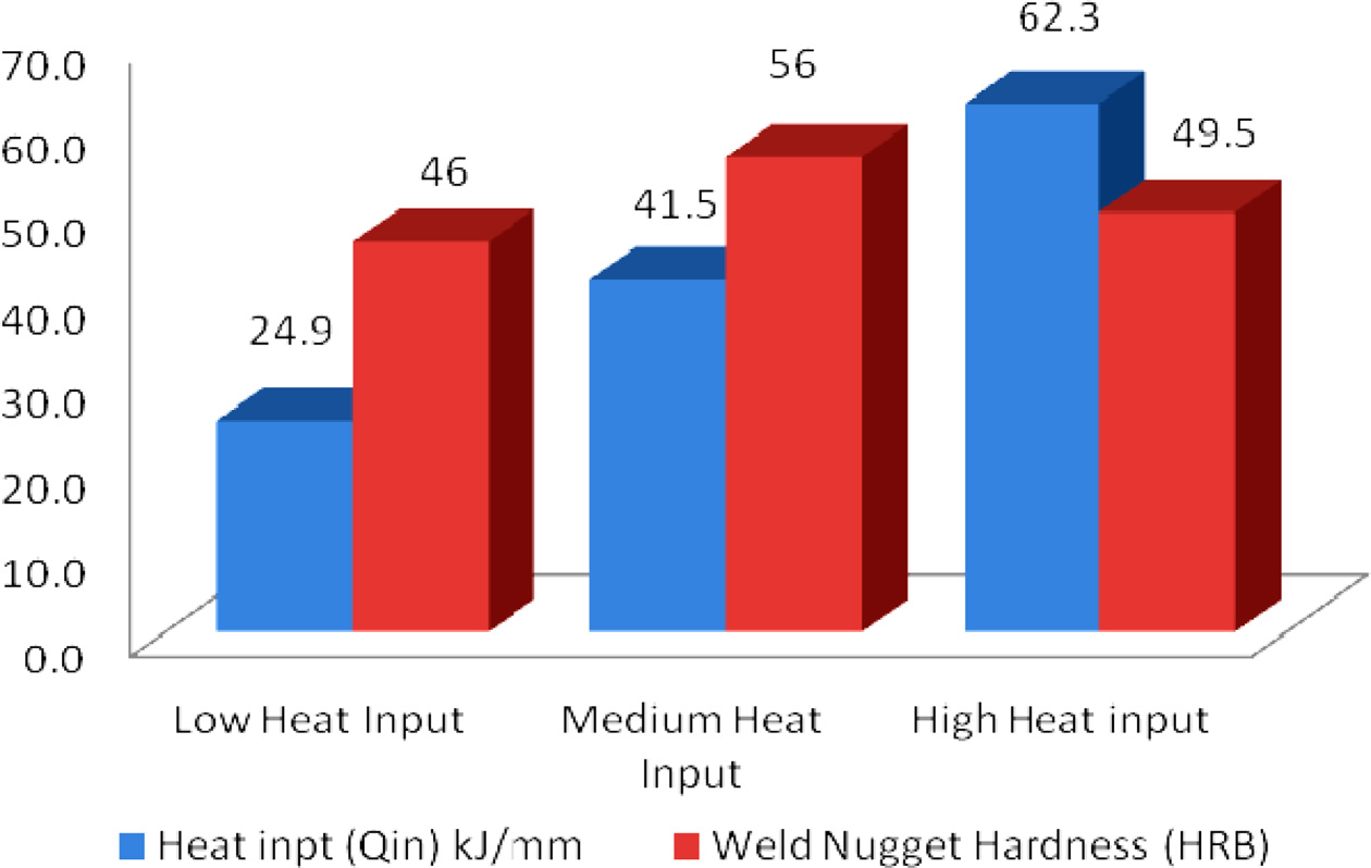
The hardness levels of the FSW’ed MMCs joints are shown in
Fig. 10. The higher hardness values were observed in
the sample 2 & 3 due to columnar dendrites with fine
and uniform mixing of matrix. Sample 1 has the resulting lower hardness value
compared to other samples because of its uneven mixing of matrix due to the
insufficient heat input.
The process parameters for these conditions were as
follow: For Low Heat Input condition, the parameters were: Tool Rotational
Speed -600 rpm, Welding Travel Speed- 50 mm/min, Axial Force- 4 kN
and the obtained Tensile strength and Hardness values were 73 kN/mm2
and 56 HRB respectively. Correspondingly, the process parameters for the Medium
Heat Input condition were: Tool Rotational Speed - 800 rpm, Welding Travel Speed-
50 mm/min, Axial Force- 5 kN, observed Tensile strength
-198 kN/mm2 and Hardness of 46 HRB. In the case of High Heat Input condition,
the parameters were, Tool Rotational Speed -1000 rpm, Welding Travel Speed- 50
mm/min, Axial Force- 6 kN which resulted in the observed Tensile strength of
124 kN/mm2 and Hardness of 49.5 HRB.
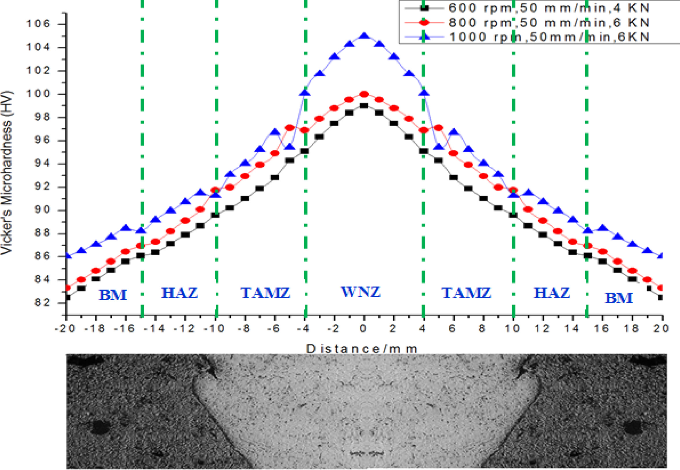
While Fig. 11 shows that the micro-hardness survey of
friction stir welded MMCs, it also proves the uniform mixing of
matrix and uniform heat inputs during entire friction stir welding process. In
micro-hardness survey analysis, the whole surface of FSW’ed joints was measured
against the affected zones. The result of the survey
provides accurate and detailed information about the surface
features of FSW’ed AMMCs that have fine microstructure
and multi-phases of homogeneous matrix. The weld nugget zone (WNZ)
was considered as the centre-line for the hardness measurement of test sample’s
surface, based on the centre-line the hardness values that were measured on
both sides (negative and positive) of the surface against the zones. From the
survey result, found the WNZs had highest hardness value compared with other
zones, also found the hardness values gradually reduced from centre-line to
tail ends on both sides and zones had approximately equal value range on both
sides. Based on the hardness values, the hardness range of the zones are in the
manner of
BM < HAZ < TMAZ < WNZ > TMAZ >
HAZ > BM. Furthermore, it was
found that Sample 2 & 3 ensuring higher hardness value at all zones in
comparison with sample 1 because of the uniform mixing of matrix due to the
sufficient heat inputs. The hardness is measured in Vickers Hardness scale
(HV).
|
Fig. 2 SEM micrograph of stir cast MMC material (a) sample 1, (b) sample 2, (c) sample 3. |
|
Fig. 3 Micro structural analysis FS welded MMC (a) sample 1, (b) sample 2, (c) sample 3. |
|
Fig. 4 SEM micrographs of FSW’ed MMCs of (a) Sample 1, (b) Sample 2, (c) Sample 3. |
|
Fig. 5 XRD analysis of FSW’ed MMCs of (a) sample 1, (b)
sample 2, (c) sample 3. |
|
Fig. 6 Spectrum analysis of FSW’ed MMCs of (a) sample 1, (b) sample 2, (c) sample 3. |
|
Fig. 7 (a) SEM images of FS welded MMC, (b)–(f) EDAX results from designated area for element mapping. |
|
Fig. 8 Tensile strength Analysis of FS welded MMC. |
|
Fig. 9 Load-displacement curve of FS welded joint in MMC. |
|
Fig. 10 Hardness analysis. |
|
Fig. 11 Micro-hardness survey Analysis of FS welded MMC. |
This
investigation has dealt with the metallurgical characterization of Friction
Stir Welded MMC and has observed that, the homogeneously distributed reinforcements and recrystallized grain structures
were the predominant characters of the weld zone. In the FSW’ed joints, the
weld nugget zones resulted in columnar dendrites along with even mixing of
matrix and fine microstructure, also observed the grains coarsening in the TMAZ
of the FSW’ed joints of AMMCs. During the FSW process, an optimum (Intermediate)
heat input resulted in even mixing of matrix, obtained higher mechanical and
metallurgical properties of the joints whereas, insufficient heat input lead to
uneven mixing of matrix, obtained lower mechanical and metallurgical properties
of the joint.
Metallurgical characterizations of the welded MMC were
done by SEM, EDX and EDX analyses. Microstructure comparison was done between
the WNZ, TMAZ, HAZ and BM under three heat input levels: Low heat input, Medium
heat input, and High heat input conditions. The Tensile strength and Hardness
are higher in the case of the Medium Heat Input condition when compared to low
and high heat input conditions. The process parameters for the Medium Heat
Input condition were: Tool Rotational Speed - 800 rpm, Welding Travel Speed- 50
mm/min, Axial Force- 5 kN, observed propertied were: Tensile Strength -198
kN/mm2 and Hardness of 46 HRB. The weld nugget hardness was found on
the WNZ, TMAZ, HAZ, and BM. The maximum micro hardness of 62.3HRB was observed
under 800 rpm Tool Rotational Speed, 4 mm/min Welding Travel Speed, 6 kN of
Axial Force.
- 1. W.M. Thomas, E.D. Nicholas, J.C. Needham, M.G. Murch, P. Temple-Smith, and C.J. Dawes, GB Patent No. 9125978.8 (1991).
-

- 2. A. Urena, M.D. Escalera, and L. Gil, Comp. Sci. Tech. 60[4] (2000) 613-622.
-
- 3. D. Storjohann, O.M. Barabash, S.S. Babu, S.A. David, P.S. Sklad, and E.E. Bloom, Mett. Mat. Trans. A. 36A (2005) 3238-3247.
-
- 4. F.F. Wang, W.Y. Li, J. Shen, S.Y. Hu, J.F. dos Santos, Mat. Des. 86 (2015) 933-940.
-
- 5. Y.Z. Li, Q.Z. Wang, BL. Xiao and Z.Y. Ma, J. Mat. Process. Tech. 251 (2018). 305-316.
-
- 6. A. S. Zoeram, S.H.M. Anijdan, H.R. Jafarian, and T. Bhattacharjee, Mat. Sci. Engg. 687 (2017) 288-297.
-
- 7. J. Guo, P. Gougeon, F. Nadeau, and X.G. Chen, Can. Metall. 51[3] (2012) 277-283.
-
- 8. P. S. Kumar, S.R. Shastry, and A. Devaraju, Mat. Tod. Proc. 4[2] (2017) 330-335.
-
- 9. P. Vijayavel and V. Balasubramanian, J. All. Comp. 729 (2017) 828-842.
-
- 10. R. Pandiyarajan, P. Maran, S. Marimuthu, and K.C. Ganesh, J. Mech. Sci. Tech. 31 (2017) 4711-4717.
-
- 11. X.J. Wang, N.Z. Wang, L.Y. Wang, X.S. Hu, K. Wu, Y.Q. Wang, and Y.D. Huang, Mat. Des.57 (2014) 638-645.
-
- 12. A.A. Seyed, P. Hassan, and M. Mahdi, J. All. Comp. 724 (2017) 859-868.
-
- 13. R. Ashok Kumar, M.R. Thansekhar, Metallofiz. Noveishie Tekhnol. 41[2] (2014) 203-211.
-
- 14. R. Pandiyarajan, P. Maran, N. Murugan, S. Marimuthu, and T. Sornakumar, Mat. Res. Exp. 6[6] (2019) 066553.
-
- 15. H. Lombard, D. G. Hattingh, A. Steuwe, and M .N. James, Engg Fracture Mech. 75[3-4] (2008) 341-354.
-
 This Article
-
2020; 21(6): 690-698
Published on Dec 31, 2020
- 10.36410/jcpr.2020.21.6.690
- Received on Jul 21, 2020
- Revised on Oct 7, 2020
- Accepted on Oct 23, 2020
Services
Shared
Correspondence to
- R. Pandiyarajan
-
Assistant Professor, Dept. of Mechanical, K.L.N College of Engineering -Pottapalayam, Tamil Nadu-63061, India
Tel : +91 9940833549 - E-mail: pandiyan.rajan8@gmail.com
Clean-Energy Research Institute(CRI), Hanyang University, 222, Wangsimni-ro, Seongdong-gu, Seoul, 04763, Korea
E-mail: jcpr@hanyang.ac.kr