- Parametric studies in friction stir welding on Al-Mg alloy with (HCHCr) tool by Taguchi based desirability function analysis (DFA)
C. Chanakyana,* and S. Sivasankarb
aResearch Scholar, Department of Mechanical Engineering, Government College of Engineering, Thanjavur, Tamilnadu, India
bAssistant professor, Department of Mechanical Engineering, Government College of Engineering, Thanjavur, Tamilnadu, India
The present investigation is
to optimize the welding parameters designed for friction stir welding (FSW) of
aluminium magnesium alloy (AA5052). The authentic configuration of automated
linear friction stir welding machine used to weld the AA5052. The experiments
were conducted by selecting the different welding process parameters like tool
rotation speed (rpm), traverse speed (mm/min), and tool pin profiles. The pin
profile made with ceramic tool type (high carbon high chromium). Taguchi based
desirability function analysis engaged in establishing the optimal process
parameters with multi-objective function in order to maximize the tensile
strength and the nugget hardness. The welding parameter of optimum level was
attained by the highest composite desirability value. An optimal level of
welding parameters acquired the tool rotation speed at 1200 rpm, traverse speed
at 30 mm/min, and the pentagonal tool pin profile. Further, ANOVA (analysis of
variance) implemented to intimate the major impact of welding parameters on the
output responses (tensile strength and nugget hardness). An outcome perceived
that the tool pin profiles and tool rotational speed are the important
consequence factors to manipulate the mixed output responses. Contour plots and
mean effect show that the interaction of parameters of welding on the required
output response.
Keywords: DFA, HCHCr tool, FSW, Tensile, Microhardness, Microstructure
In the fusion welding process, the joining of aluminium
alloy was inflexible, and blemish joints occurred due to a low melting point
and high shrinkage. The welding institute introduced Friction stir welding
(FSW) to solve this issues in the fusion welding process. There are many
benefits in FSW such as, better mechanical properties, fine grain structure,
free porosity, and extending the enormous amount of production in the
automotive and marine sectors [1]. For setting the optimal level of welding
process parameters, it is indispensable to produce the exceptional quality of
the welding. There are different methods available to detect the optimal
parameters of welding in which Desirability function analysis (DFA) is found as
a precise method because it is less time consuming and materials for this
current investigation [2]. Periyasamy et al. [3] reported the multi-objective
optimization of FSW on the metal matrix composites by using the desirability
function. The optimum process parameters of welding were achieved by
desirability function to improve the responses of tensile strength, hardness,
and notch strength. Ambedkar et al. [4] examined the process parameters of FSW
multi-response by the approach of principal component analysis and artificial
neural network. They conducted the experiments on AA2024 aluminium alloy by
utilizing the friction stir welding. These approaches considered the control
factors as weld speed, tool rotation speed, and the tool dimensions ratio. They
determined 3 D/d ratio, 670 r/min spinning speed of tool, and 0.017 m/min weld
rate of optimal parameters by using principal component analysis. Devaiah et
al. [5] summarized the dissimilar FSW between the AA5083 and AA6061 to attain
the optimal welding parameters by utilizing the Taguchi. The most influencing
parameters of weld rate and spinning speed of tool was indicated by the ANOVA
outcomes and statistical model to create the correlation among the input
variable and the result responses. The Taguchi technique produced the optimal
parameters such as 1,120 rpm rotation speed of tool, 70 mm/min traverse
speed, and 20o tilt angle from the multi-objective optimization.
Devarasiddappa et al. [6] discussed the optimization of multi-objective in the
WEDM process of the material Inconel 825 which composed by
desirability function. The composite desirability produced the
pulse off time for significant impact compared to other parameters namely peak
current and pulse on time. The output responses namely surface roughness-SR and
material removal rate-MRR with percentage of 3.73, 1.22, and 4.46, respectively.
Jenarthanan et al. [7] studied the impact of friction stir dissimilar welding
between the AA2014 and AA6061 to develop the tensile strength coupled with
ANOVA and response surface methodology. They fabricated the high strength
welding by using the control parameters such as weld speed, tool spinning, and
the diameter of the tool pin. The CCD model validated by the ANOVA and also
examines the mechanical response. John et al. [8] investigated the friction
stir processing on AA2014 for developing the mechanical properties
by the optimization and manipulate of input parameters. By an approach
of desirability based response surface methodology to optimize the
parameters of welding. The main objective of this
examination was to find the optimal tool pin profile with an approach of
desirability function. Kumar et al. [9] predicted and developed the tensile
strength with the mathematical model for dissimilar FSW between the aluminium
alloy 6061 and 2024 by ANN and Taguchi. At the 2nd level of processing parameters,
the optimum value of the tensile strength of 189.1 MPa
was obtained. The model results confirmed with an
artificial neural network produce precise tensile strength compared to the
Taguchi method. The good welded joint between the aluminium alloy 6061 and 2024
was produced with significant control parameters like weld rate, tool spinning
rate, and axial load. Shashi Kumar et al. [10] identified the
optimal process parameters of FSW on the 316 L material for
maximizing the tensile strength by RSM based Box-Behnken
design. The regression model established the response of tensile
strength of the joint as an input factor such as spindle rate, weld rate, and
axial load of tool. Those input factors significantly proved by
the response surface method and desirability approach. Further, optimal
outcomes of tensile strength 604 MPa corresponding to optimum input process
parameters followed 597 rpm tool spindle speed, 74 mm/min tool weld speed, and
3 kN downward force. Kumar Naik et al. [11] proved that the optimization and
investigation of Hardox 400 plasma arc cutting by desirability analysis based
on the Taguchi method. To improve the quality of plasma arc cutting, Taguchi
based desirability analysis-TBDA is utilized to obtain the optimal condition of cutting
parameters. The plasma arc cutting efficiency was enhanced by setting optimal process parameters, which was verified by
the confirmation test. Muthu Krishnan et al. [12] investigated the statistical
modelling for the FSW of A319 and AA6063 using the ANN and response surface
method. They proved that the welding process
parameters like welding tool, tool spindle speed, axial force and traverse
speed play an influential function in
deciding the properties of the welded joints. The method ANN predicted the
tensile strength of AA6063 and A319 FSW. The ANN regression model found the error
in predicted values which was best technique in ANN compared to other ANN
techniques. Nwobi-Okoye et al. [13] compared the modeling between artificial
neural network and neuro-fuzzy system for multi-objective optimization of age hardening on A356 aluminium alloy. The
neuro-fuzzy system with a coefficient 99.8% was the predicted hardness values
which are finer than the artificial neural network having coefficient 99.2%. So
that outside experimental points of ANN, which were the fitness functions of
age hardening parameters using the
(GA) genetic algorithm. Banglong Fu
et al. [14] reported that the dissimilar friction stir welded joints between
the AZ31B and AA6061 alloy. The transitional combination of rate of tool
rotation 600rpm to 800rpm, the cross speed 30 mm/min to 60 mm/min and tool
offset 0.3mm to obtain the welding. The eutectic structure survived in the
nugget zone due to the intermetallics compounds of base metal. The tensile strength
of the dissimilar joint reached 70% of AZ31B base metal. The spindle torque
used to compute the heat-input between the base metal of AZ31B and AA6061
throughout the FSW process. The selected welding condition composed of the
proper heat input and material mixing, which was studied in this investigation. Arun Kumar Kadian et al. [15]
studied the material flow movement
between the dissimilar AA 6061 aluminium alloy and B370 copper alloy through
the friction stir welding. The material flow for the dissimilar FSW on the base
material has been projected and
located on the strain rate and temperature distribution. The temperature distributions were irregular in
the welded samples because of the enormous amount of heat transmitted in copper
material than the aluminium material. By maximizing the tool spinning speed,
the material movement in welded plates can be improved. During the corrosion
test, the volume of the fluid level was lower in the nugget region of the
copper alloy due to lesser fluidity at the higher welding temperature. Palani
K. et al. [16] conducted the dissimilar FSW on AA 8011 and AA 6061 al alloys.
The three different tool pin profiles, such as hexagonal, pentagonal, and
square, were played an essential role in promoting mechanical behavior during
the welding process. The 1,500 rpm spinning speed of the tool, 40 mm/min
traverse speed, and 2.5 mm depth of plunge with the hexagonal pin profile composed the excellent
mechanical properties of dissimilar welded joints. Next to
hexagonal pin profile, pentagonal pin
produced defect-free AA 8011 and AA 6061 al alloy welded joints. Prabhakar et
al. [17] investigated the FSP along with composite material of 5083 aluminium
alloy and its reinforcement of fly ash particles. The FSP was fabricated at tool
speeds 1,400 rpm, and varying weld
speed of 20 and 25 mm/min which was concluded as the optimal condition. The
maximum hardness attained in processed
composite specimens when compared with base metal 5083. The current density of corrosion was maximized with
processed 5083 aluminium alloy. The
Al 5083 composites of processed specimens accomplished the fine grain size due
to the presence of fly ash particles. Successfully, the researchers improved the performance of
mechanical characteristics of processed composite 5083 aluminium alloy. Gopi Krishnan et al. [18]
had undergone the stir casting method with aluminium oxide and silicon carbide
to produce the welded joints of AA7010. The working parameters, namely, axial force, traverse speed, and tool spinning speed, were varied. The
welding parameter was designed with
the L27 Taguchi technique. This
investigation focused on the development of welded tensile strength by using
regression analysis. The optimized parameters were done by the method of the
Genetic algorithm.
In the present investigation, Taguchi based desirability
function analysis implemented to determine the optimal process parameters for
the Friction Stir Welded joints of AA5052, which was performed by ceramic tool
material. There are several strengthening tool materials, namely,
HSS, die steel, etc. Among these tool materials, high carbon
high chromium (HCHCr) is a ceramic tool that possesses
better strength for treating the surface of metals to
improve the metallic characteristics in aluminium alloy. Moreover, ANOVA
implemented to resolve the most critical impact of concerned
parameters for the multiple responses, namely, tensile strength and nugget
hardness. At last, the optimum process parameters confirmed by
performing the verification test.
In this investigation, the friction stir welding of AA5052
was fabricated in FSW machine. AA5052 was good selection for integrated among
aluminium alloys due to fine weldability, wear resistance, better
corrosion, and superior hardness. Chemical composition and properties of the
AA5052 base showed in Tables 1 and 2, correspondingly. HCHCr (High Carbon High Chromium Die Steel) utilized to manufacture the
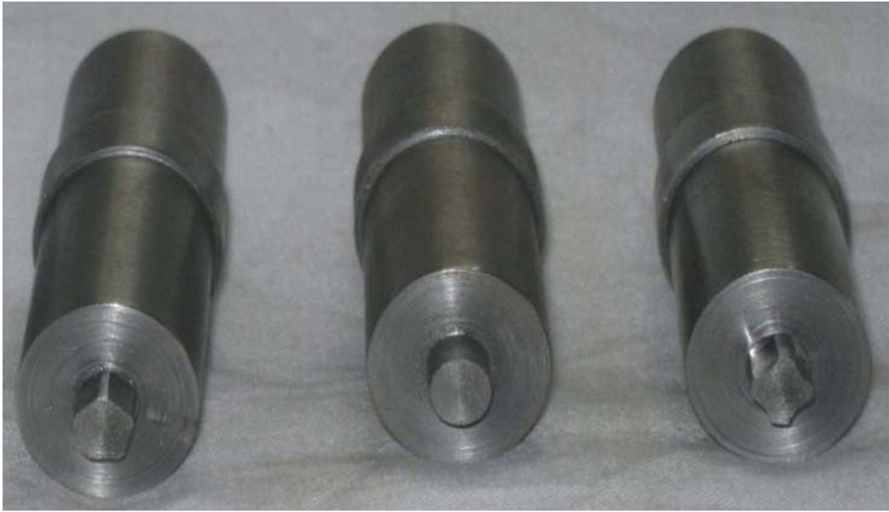
FSW tool. Fabricated tool pin profiles such as a Pentagonal pin cylinder (PC),
straight cylinder (SC), and fluted cylinder (FC) displayed in Fig. 1. Aluminium
alloy AA 5052 plates were having dimensions (100 mm ´ 50 mm ´ 6
mm), which are the required size of both specimen [19]. Square butt joint
designed with size of 100 mm ´
100 mm and equipped with welded joints. In the framework of single-pass
welding, the welded joint was created. The revolving direction was typical for
the welding direction with constant axial load of 5 kN was applied for all the
experimentation. Table 1, 2
Fig.
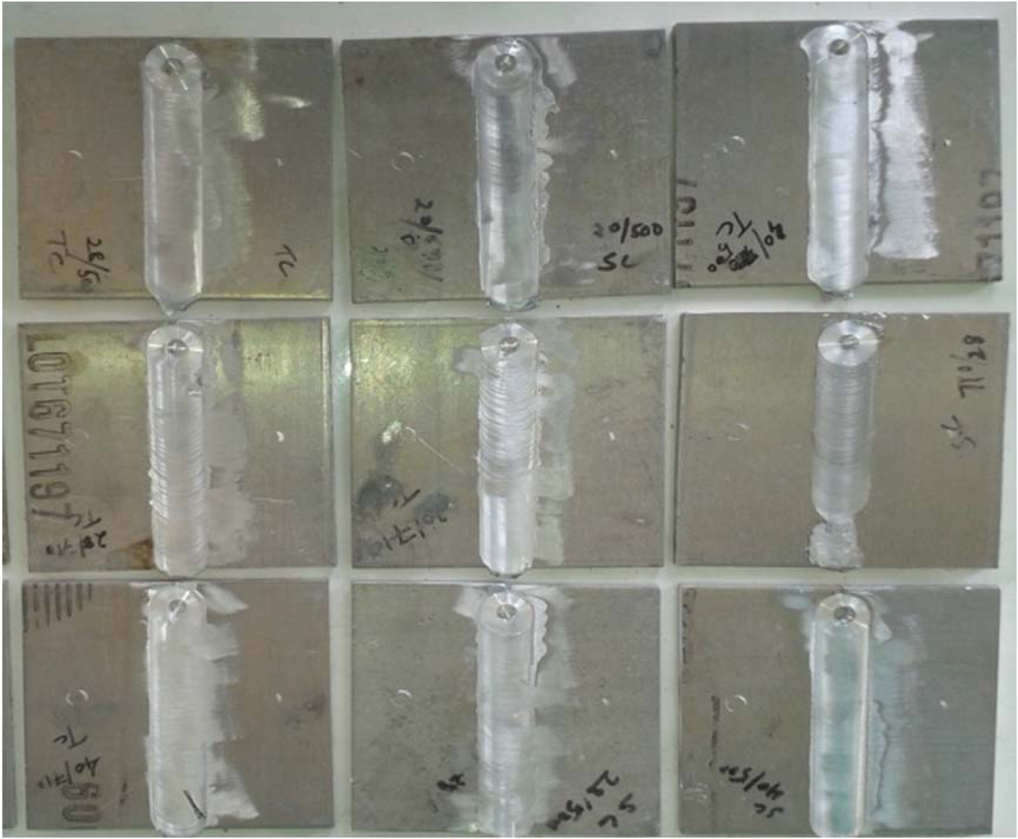
2 exhibits the photographic view of friction stir welded joints of AA5052.
During the investigation, influence of tensile strength and nugget hardness of
FSW on various welding parameters were examined. In present examination, the
impacts of process parameters of welding with 3-levels were chosen and it’s
given in Table 3. The L9 orthogonal array selected for
investigational outline of friction stir welding [20]. Tensile strength
verified by the UTM-universal testing machine
as per the standard of ASTM E9 used to prepare the tensile specimens. The
microhardness analyzer with 0.5 N loads used to calculate the nugget hardness
at three various spots for each nugget zone surface of welded specimen and the
nugget hardness average value was
measured. Investigational input process
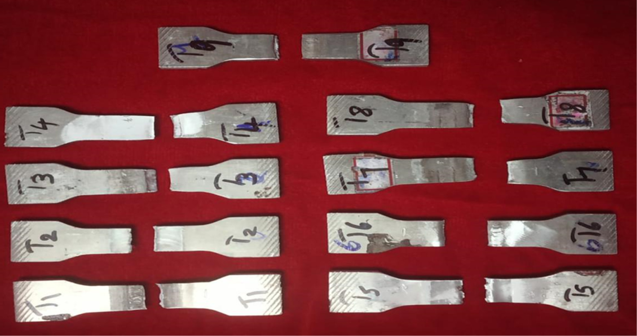
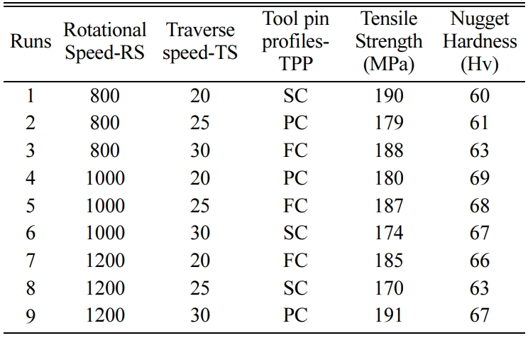
parameters of FSW and the outputs were exhibited in Table 4. Similarly, the
photographic view of fractured tensile specimen displayed in Fig. 3.
|
Fig. 1 The fabricated FSW tool pin profiles |
|
Fig. 2 Friction stir welded joints of AA5052. |
|
Fig. 3 Fractured tensile specimen of FSWed AA5052. |
Desirability
Function Analysis (DFA)
Derringer and Suich proposed the Desirability function analysis
on optimizing multi-objective attributes conditions [21]. DFA utilized to
transform multiple-response attributes
interested in single response attributes among the composite desirability
inspection [22]. In present experimentation, the multiple responses namely
tensile strength and nugget hardness mixed as composite desirability method. The following steps of DFA
presented below:
Step (1): For all results of responses should be
calculated by the individual desirability index (di). Three equations utilized
to determine the index of individual desirability [23].
Larger-the-better found to be the target for maximum
objective function by using the following equation.

Nominal-the-best found to be a goal for appropriate
objective function by using the following equation.

Smaller-the-better found to be a goal for minimum
objective function by using the following equation.

Here, Xmax is the greatest value of ‘X’, Xmin
is the lowest amount of ‘Y’. T- Signifies target values. The weight of the
responses results was denoted by s, t, r. In the current investigation, tensile
strength and nugget hardness were measured while the larger-the-better
attributes.
Step (2): The individual desirability index of all
responses are combined and used to determine the (dG) composite
desirability by subsequent equation.

Here, di denotes the individual
desirability index along with wi signifies weight of the output
response.
Step (3): Once obtaining the composite desirability
results, the optimal combination of the parameter level was measured. Commonly,
composite desirability maximum value
measured towards the optimum level of
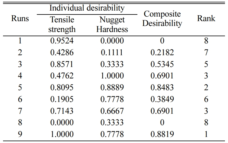
process parameters. Manipulated composite desirability among rank order was presented in Table 5.
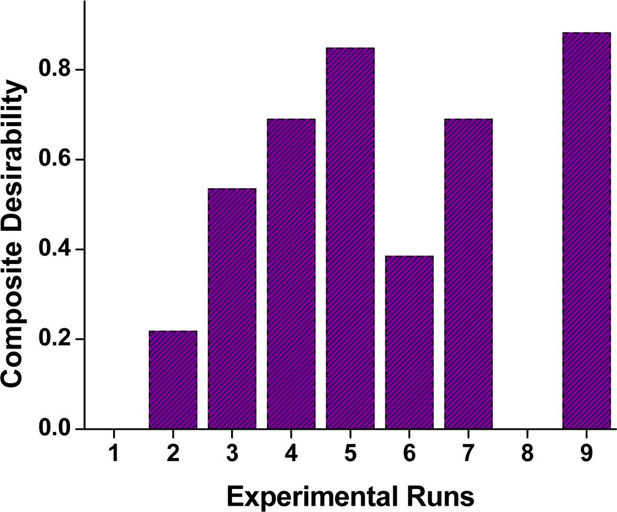
Fig. 4 exhibits the rank plots between the composite
desirability and the nine experimental runs. The Fig. 4 observed the 9th
experiments attains the maximum of composite desirability. In which the 9th
experiments intimates a superior combination of optimum level of welding
parameters tool rotation speed (1,200 rpm), tool traverse speed (30 mm/min),
and pentagonal pin profile. Multi-response attributes to maximize the tensile
strength and nugget hardness during the process of FSW on AA5052.
Analysis
of FSW process parameters on composite desirability
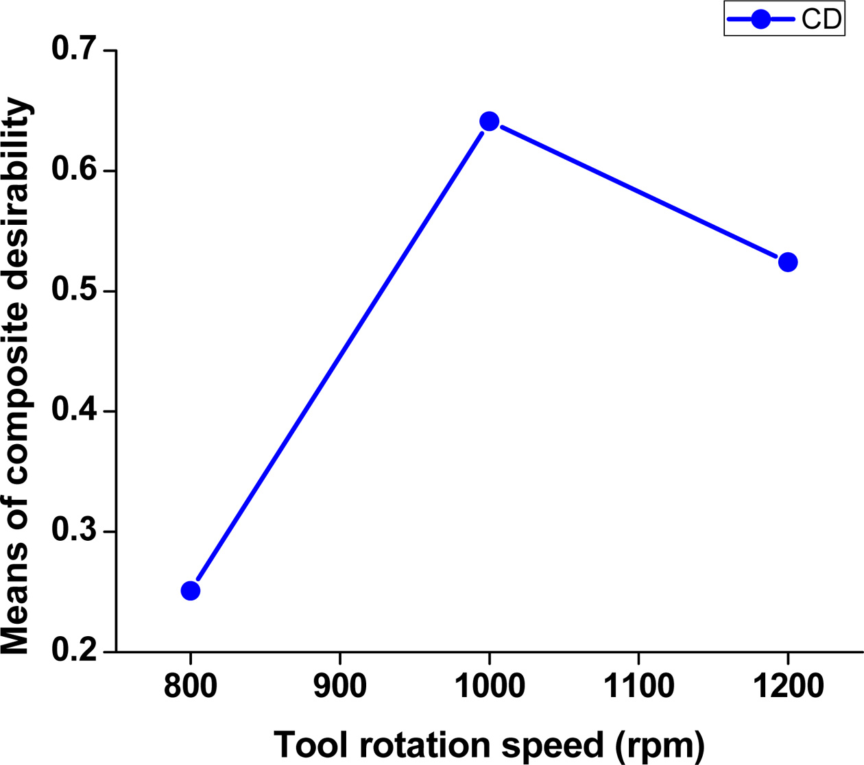
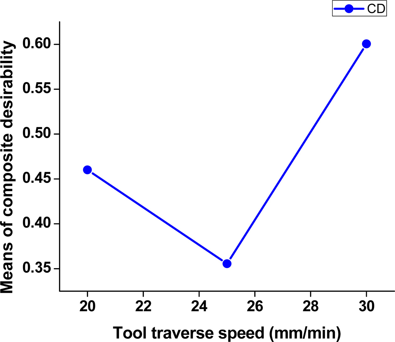
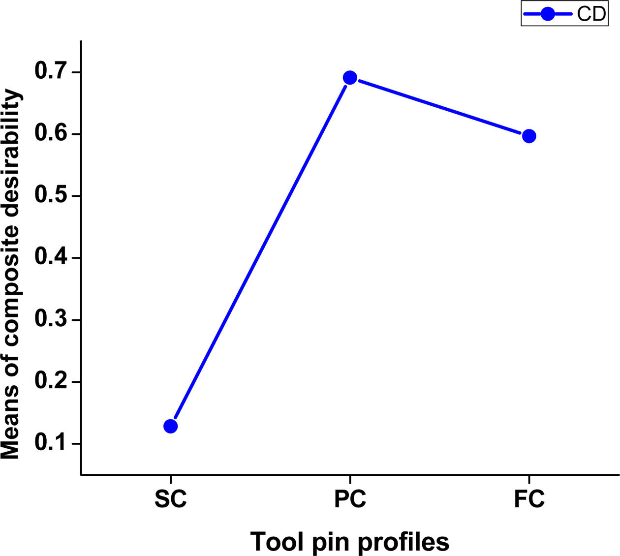
Fig. 5 to 7 6 presented means of composite desirability with
various FSW parameters. From the plots, the dotted line
signifies the mean value of composite desirability. It is observed that the
plots and the maximum value indicate the predicted
characteristics of multiple responses. It indeed that the optimal
level of FSW parameter arrangements obtained at the level A3B3C2,
which intimates that the tool rotation speed
(1,200 rpm) at level 3, tool traverse speed (30 mm/min) at level 3, and tool
pin profile (pentagonal cylinder) at level 2. Above the mentioned level of
welding process parameters enhances the multi-responses of tensile strength and
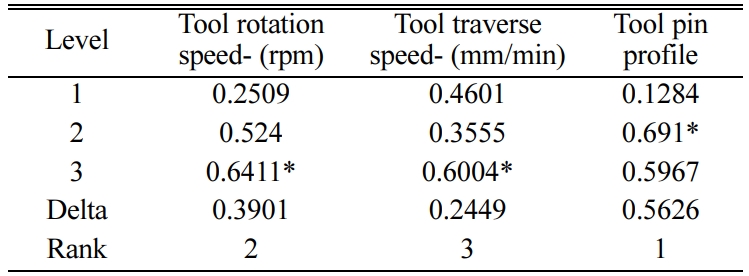
nugget hardness during the FSW process of AA5052 aluminium alloy. The mean and
the average composite desirability for every process parameters level was
displayed in Table 6. Therefore, table 6 clearly explains the order of control
process parameters verified by the delta result. The highest delta value
indicated as 1st rank, which denotes that, the control parameter
which are the significant impact of output response. From mean table, the tool
pin profile parameter was a significant aspect of the multiple performances of
the developed welding process
followed by the tool rotation speed.
Analysis
of composite desirability
ANOVA objective is to manipulate the FSW parameters with
contributions of integrated multi-response qualities [24].
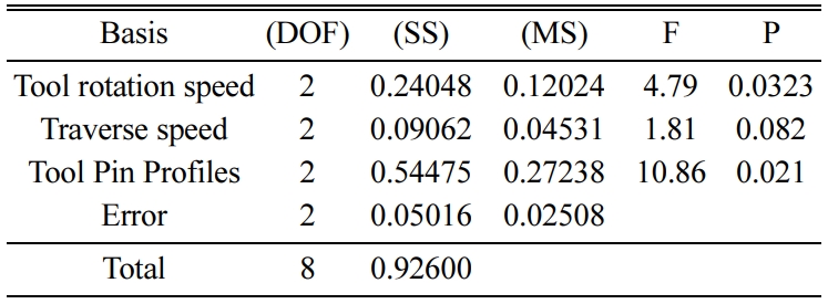
Table 7 exhibited the ANOVA results of composite
desirability. ANOVA results proved that the tool pin profile was the most
influencing factor in which 62.1% contribution followed by tool rotation speed
contributes 27.4%. The lowest contribution of 10.3% occurred in tool traverse
speed. At a 95% confidence interval, the significant process parameters were
indicated by less than 0.05 of P-value. In this analysis, tool pin profiles (p
= 0.021) and tool rotation speed (p = 0.032) severely affecting the
process parameters on the output of multiple responses through the FSW of
AA5052 [25].
Contour
plot analysis for composite desirability
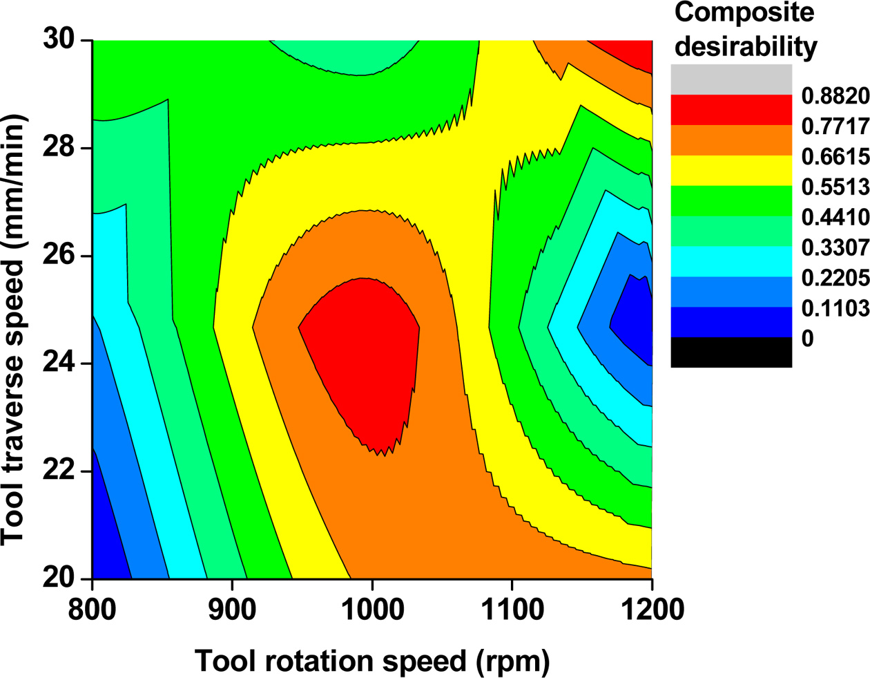
Fig. 8-10 exhibits the desirability contour plots with
processing parameters of welding at different levels. In Fig. 8 showed, the
impact of tool rate and tool traverse speed of composite desirability value. It
is perceived that the value of composite desirability was increased while
increasing the rate of tool rotation and weld speed. Maximum desirability value
of 0.8820 was occurred at the tool rotation speed (1,200 rpm) and tool traverse
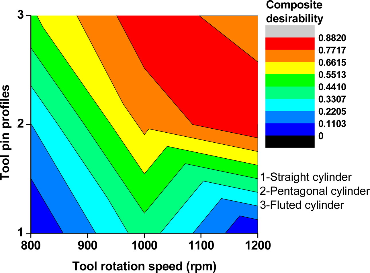
speed (30 mm/min). In Fig. 9 showed that the effect of tool speed and three pin
profiles of composite desirability value. It revealed that the tool rotation
speed (1,200 rpm) and pentagon pin profile produces the highest composite
desirability value. Due to higher tool rotation produced higher friction
between the base metal and the tool, thus the outcomes improved the tensile
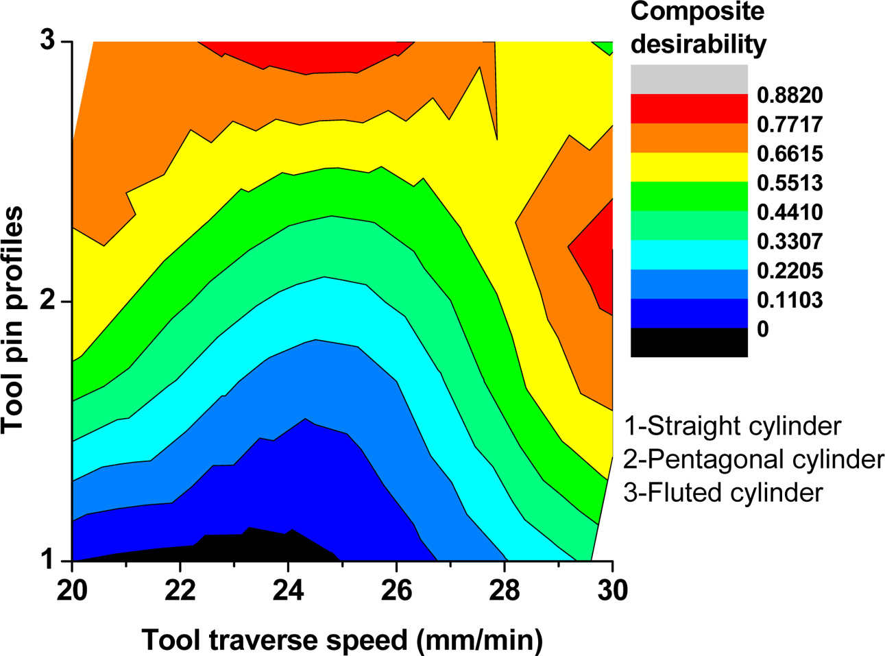
strength and nugget hardness. In Fig. 10 represents the
response of tool traverse speed and tool pin profiles of the
desirability values, the maximum value of composite desirability
attained at the 30 mm/min tool traverse speed and pentagonal tool pin profile
parameters.
Confirmation
analysis of composite desirability
The verification test engaged to verify the
investigational outcomes. An optimal level of FSW
parameters utilized to validate the multi-response
qualities during the process on AA5052. By
using below the equation, the predicted value of
composite desirability was determined.

The composite desirability of
average value and the mean value indicated by hm and hi by the optimum level of process parameters. K-denotes
the number of FSW parameters. Predicted,
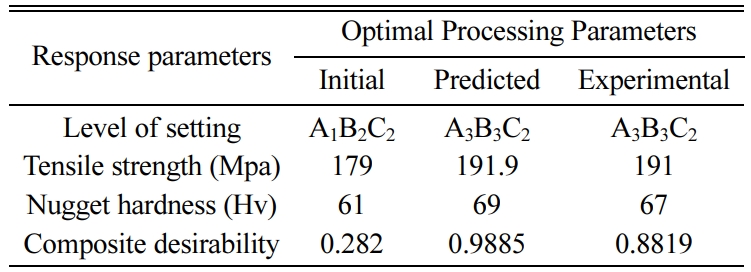
experimental and improved percentage on composite desirability value was presented in Table 8.
|
Fig. 4 The composite desirability vs the nine experimental runs. |
|
Fig. 5 Means of composite desirability vs Tool rotation speed. |
|
Fig. 6 Means of composite desirability vs Tool traverse speed. |
|
Fig. 7 Means of composite desirability vs Tool pin profiles |
|
Fig. 8 Contour plot of composite desirability for Tool traverse
speed vs Tool rotation speed. |
|
Fig. 9 Contour plot of composite desirability for Tool pin
profiles vs Tool rotation speed. |
|
Fig. 10 Contour plot of composite desirability for Tool pin
profiles vs Tool traverse speed. |
The optical microscopy investigation was conducted on the
microstructure analysis of the entire AA5052 welded region with the influence
of various welding parameters. The micrographs of stirred zone of joints were
observed to dynamic recrystallization appeared during the welding. Also
mentioned variations in grain size and homogeneity were determined in the
welding technique [26]. The grain size was measured at three deformation
zones, namely the nugget zone (NZ), thermo-mechanically
affected zone (TMAZ), and heat-affected zone (HAZ). Heyn’s line intercept
technique applied to determine the (AGD- Average Grain Diameter) of stirred
zone on welded specimens. The granular grains of the base metal modified to
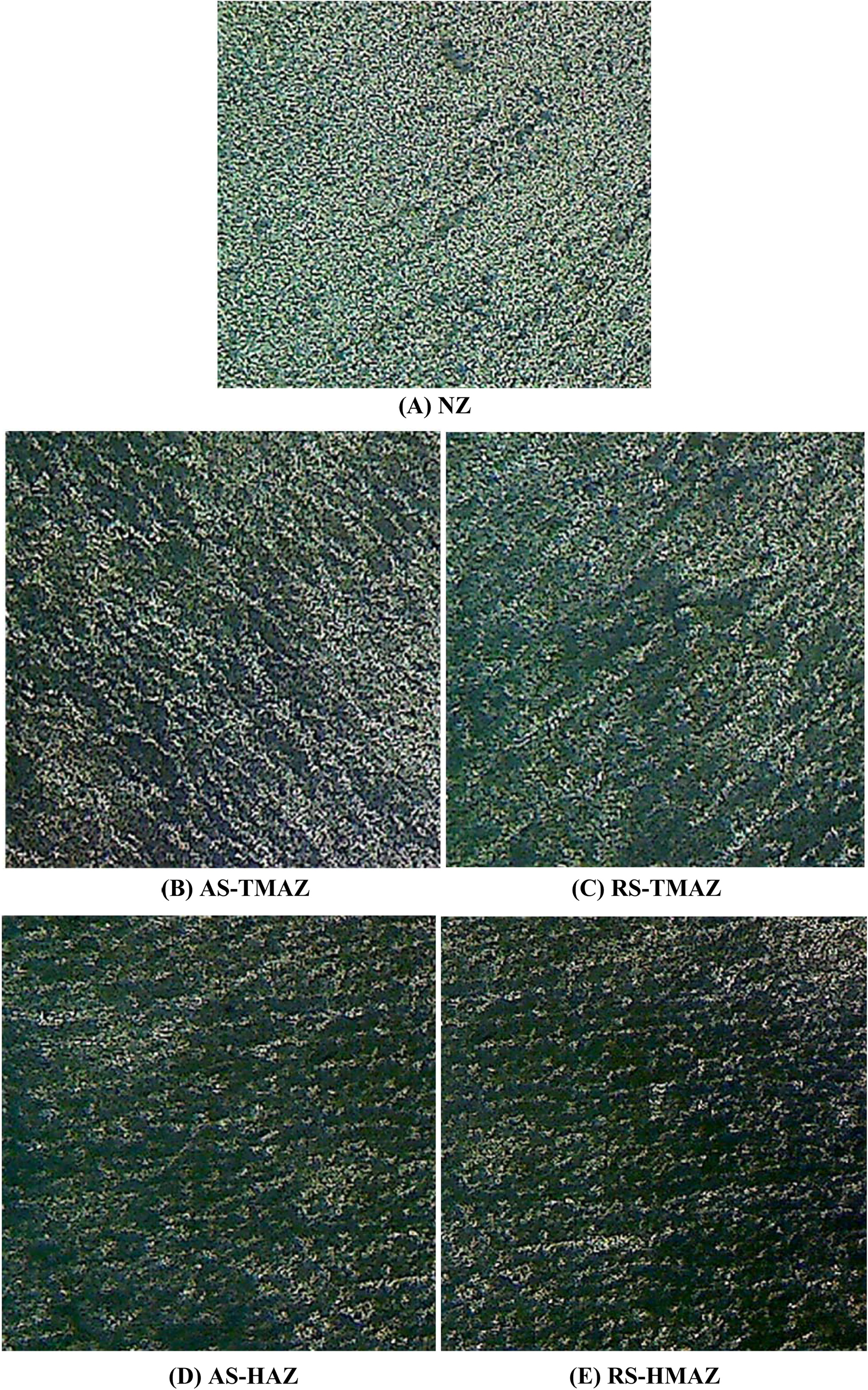
fine grains in the nugget zone. The microstructure of fabricated FSW joints
utilizing the optimum parameters were shown in Fig. 11. Mentioned
figure shows the grain structure of friction stir welded
at different zones with magnification of 100 ´
and 100 μm. In all the welded specimens, the nugget zone grain size is much
smaller than the TMAZ and HAZ. The advancing and retreating side of the TMAZ
grain size is finer than that of the HAZ. The welded joints thermo mechanically
affected zoneadvancing side (TMAZ-AS) fabricated by the indicated process
parameters exhibits coarse and elongated of deformed grains at the welded
interface. The welded joints thermomechanically
affected zone - retreating side (TMAZ-RS) shows the elongated
oriented grains due to the deformation of the welded interface
was slowly reduced. The heat affected zone on advancing side (AS) and
retreating side (RS) micrographs show the coarsening of grain
occurred in HAZ due to mechanically influenced deformation
not occurred [27-29]. Fig. 11 presents the microstructures
of various zones at the optimum process parameters
with tool rotation speed (1,200 rpm), traverse speed (30
mm/min), and the pentagonal cylinder tool pin profile. The nugget zone grain
size is much smaller than the TMAZ and HAZ. The advancing
and retreating side of the TMAZ grain size is finer than that of
the HAZ. The average grain diameter at the nugget zone is 1.59 μm.
|
Fig. 11 Microstructure of different zones at the optimum process parameters 1,200 rpm, 30 mm/min and pentagonal cylinder tool . |
1. The FSW of AA5052 aluminium alloy was
effectively fabricated throughout this welding process and the optimal
process parameters of FSW was investigated.
2. Taguchi based desirability function analysis
was successfully employed to verify the optimum level of welding parameters
during welding process.
3. The optimal level of process parameters are
tool rotation speed (1,200 rpm),
tool traverse speed (30 mm/min) and the pentagonal pin profile achieved maximum
tensile strength and nugget hardness.
4. ANOVA outcomes showed, the tool pin profiles
was the most significant factor for output responses with contribution of
62.1%. Subsequently, tool spinning rate and weld speed contributes the 27.4%
and 10.3%.
5. The confirmation analysis of composite
desirability utilized to validate the optimum level of process parameters
so as to improve the composite desirability with
68.02%.
The authors express their genuine gratefulness to
Coimbatore institute of technology (CIT), Coimbatore providing the amenities
for conduct of the research.
- 1. T.A. Barnes and I.R. Pashby, J. Mate. Proc. Tech. 99[1-3] (2000) 62-71.
-

- 2. S.V. Alagarsamy, M. Ravichandran, S. Dinesh Kumar, S. Sakthivelu, M. Meignanamoorthy, and C. Chanakyan, Mate. Today. Proc. 27[2] (2020) 853-858.
-

- 3. P. Periyasamy, B. Mohan, V. Balasubramanian, S. Rajakumar, and S. Venugopal, Tran. Nonf. Meta. Soci. Chin. 23[4] (2013) 942-955.
-

- 4. M. Ambekar and J. Kittur, Mate. Today. Proc. 27[1] (2019) 363-368.
-

- 5. D. Devaiah, K. Kishore, and P. Laxminarayana, Mate. Today. Proc. 5[2] (2018) 4607-4614.
-

- 6. D. Devarasiddappa, M. Chandrasekaran, and M.T. Sambandam, Mate. Today. Proc. 5[5] (2018) 11531-11547.
-

- 7. M.P. Jenarthanan, C. Varun Varma, and V. Krishna Manohar, Mate. Today. Proceedings 5[6] (2018) 14384-14391.
-

- 8. J. John, S.P Shanmuganatan, and M.B Kiran, Mate. Today. Proc. 5[11] (2018) 25458-25467.
-

- 9. A. Kumar, M.K. Khurana, and G. Singh, Mate. Toda Proc. 5[11] (2018) 25440-25449.
-

- 10. S. Shashi Kumar, N. Murugan, and K.K. Ramachandran, Measurement. 137 (2019) 257-271.
-

- 11. D.K. Naik and K.P. Maity, Mate. Today. Proc. 5[5] (2018) 13157-13165.
-

- 12. M. Muthu Krishnan, J. Maniraj, R. Deepak, and K. Anganan, Mate. Today. Proc. 5[1] (2018) 716-723.
-

- 13. C.C. Nwobi-Okoye, B.Q. Ochieze, and S. Okiy, J. Mate. Rese. Tech. 8[3] (2019) 3054-3075.
-

- 14. B. Fu, G. Qin, F. Li, X. Meng, J. Zhang, and C. Wu, J. Mate. Proc. Tech. 218 (2015) 38-47.
-

- 15. A.K. Kadian and P. Biswas. J. Manuf. Proc. 34 (2018) 96-105.
-

- 16. K. Palani, C. Elanchezhian, B. Vijaya Ramnath, G.B. Bhaskar, and E. Naveen, Mate. Today. Proc. 5[11] (2018) 24515-24524.
-

- 17. Prabhakar, N. Ravi Kumar, and B. Ratna Sunil, Mate. Today. Proc. 5[2] (2018) 8391-8397.
-

- 18. P. Gopi Krishnan, B. Suresh Babu, and K. Siva, J. Ceram. Process. Res. 21[2] (2020) 157-163.
- 19. C. Chanakyan and S. Sivasankar, Inte. J. Rapi. Manu. 8[1/2] (2019) 147-160.
-

- 20. C. Chanakyan and S. Sivasankar, M. Meignanamoorthy, M. Ravichandran, and T. Muralidharan, Mate. Toda. Proc. 21 (2020) 231-236.
-

- 21. B. Singaravel and T. Selvaraj, J. Adva. Manu. Syst. 15[1] (2016) 1-11.
-

- 22. M. P. Jenarthanan and R. Jeyapaul, Inte. J. Scie. Tech. 5[4] (2013) 23-36.
-

- 23. P. Sengottuvel, S. Satishkuma, and D. Dinakaran, Proc. Engi. 64 (2013) 1069-1078.
-

- 24. S.V. Alagarsamy and M. Ravichandran, Indu. Lubr. Trib. 71[9] (2019) 1064-1071.
-

- 25. R. Bobbili, V. Madhu, and A.K. Gogia, Engi. Scie. Tech. Inter. J. 18[4] (2015) 720-726.
-

- 26. G. Ugrasen, G. Bharath, G. Kishor Kumar, R. Sagar, P.R. Shivu, and R. Keshavamurthy, Mate. Toda. Proc. 5[1] (2018) 3027-3035.
-

- 27. K. Meena, A. Kumar, and S.N. Pandya, Mate. Toda. Proc. 4[2] (2017) 1978-1987.
-

- 28. H, Fujii, L. Cui, M. Maeda, and K. Nogi, Mate. Scie. Engi. A. 419[1-2] (2006) 25-31.
-

- 29. P. Thread Gill, Science and Technology of Welding and Joining 12[4] (2007) 357-360.
-

 This Article
-
2020; 21(6): 647-655
Published on Dec 31, 2020
- 10.36410/jcpr.2020.21.6.647
- Received on May 15, 2020
- Revised on Aug 15, 2020
- Accepted on Sep 4, 2020
 Services
- Abstract
introduction
materials and methods
result and discussion
microstructure
conclusion
- Acknowledgements
- References
- Full Text PDF
Shared
 Correspondence to
- C. Chanakyan
-
Research Scholar, Department of Mechanical Engineering, Government College of Engineering, Thanjavur, Tamilnadu, India
Tel : +91 9786964398 - E-mail: chanmech89@gmail.com


 Copyright 2019 International Orgranization for Ceramic Processing. All rights reserved.