


- Effect of process gas on deposition efficiency of zirconia film in granule spray in vacuum
Ochirkhuyag Tungalagtamira,b, Yoon-Soo Parka, Jaewon Leec, Scooter D. Johnsond, Dong-Soo Parkb and Chan Parka,*
aDepartment of Materials Engineering, Pukyong National University, Busan 48547, South Korea
bFunctional Ceramics Department, Korea Institute of Materials Science, Changwon, Gyeongnam, South Korea
cDepartment of Aero Materials Engineering, Jungwon University, Goesan, Chungbuk, South Korea
dMaterials Science and Technology Division, Naval Research Laboratory, Washington, DC, +USA
Monoclinic zirconia films were
deposited by spraying monoclinic zirconia granules on glass substrates in a low
vacuum environment. In order to spray the granules through a nozzle, air and He
were used to carry and accelerate the granules. Flow rates of air and He were
varied in order to study their effect on granule velocity and deposition
efficiency. For both air and He, granule velocity increased with their flow
rate. For the same gas flow rate, granule velocity was much higher when He was
used than when air was used. Variation of deposition efficiency according to
the gas and gas flow rate was similar to that of granule velocity. Highest
deposition efficiency was 1.87% which may be the highest deposition efficiency
of ceramic films by room temperature spray of ceramic particles or granules to
date. The results support that granule velocity is closely related to
deposition efficiency. The deposited films were quite dense and retained the
crystalline phase of the granules.
Keywords: Granule spray in vacuum (GSV), Zirconia film, Deposition efficiency, Granule velocity, Process gas
Aerosol deposition method (ADM) has been attracting a
lot of attention mainly due to its unique advantages for making ceramic films
[1-7]. It can deposit dense nano-structured ceramic films simply by spraying
the individual fine ceramic particles (with a particle size range of 0.08-2 μm)
mixed in a carrier gas through a nozzle in a vacuum chamber at room temperature
[1]. The deposited films have almost the same chemical composition as that of
the starting ceramic powder. ADM can also deposit films fast especially when
the film area is small. Although ADM has such attractive merits
for making ceramic films, it still needs improvement for a better
performance [8]. For example, Mihara et al. pointed out a problem with the
aerosol chamber which was mechanically vibrated for generating the aerosol [8].
The mechanical vibration gradually changed the state of powders from floppy to
densely packed inside the aerosol chamber. As the powders were densely packed,
the amount of particles floating up in the aerosol chamber and
mixed in a carrier gas decreased. That means the amount of particles delivered
to the nozzle by a carrier gas decreased as the deposition proceeded.
Granule Spray in Vacuum (GSV) was developed in order to
attain long-term-feed stability of of ADM. Since
flowable granules are used, GSV does not require mechanical
vibration for feeding the raw materials to a nozzle and thereby long-term-feed
stability can be accomplished. Details of GSV were introduced in the previous
reports [9, 10]. GSV is similar to ADM in many aspects. For example, it
deposits dense ceramic films at room temperature as ADM does [9]. There are
some differences between ADM and GSV, too. One of the biggest differences can
be found in what collides with the substrate. While individual particles well
dispersed in a carrier gas impinge upon the substrate in ADM, spherical
agglomerates of particles (granules) collide with it in GSV.
An important issue about both ADM and GSV may be the
deposition efficiency (DE) that is defined as mass of the deposited film
divided by mass of powder consumed. DE is considered important especially when
the film thickness and area are large. A high DE can decrease both the
deposition time and the raw material consumption at the same time. Naoe et al.
reported that DE of ADM for Al2O3 was as low as 0.088%
[11]. Johnson et al. reported average DE of 0.082% for barium hexaferrite films
deposited by ADM [12]. They found DE of ADM barium hexaferrite film weakly
increased with deposition time. Fuchita et al. reported on aerosol gas
deposition (AGD) of zirconia powder [4]. Details of AGD seem very similar to
ADM and may be categorized as the same method as ADM. Although Fuchita et al.
did not provide DE specifically in the report, we can estimate DE of the
zirconia film formation using data in the article and the theoretical density
of monoclinic zirconia (5.84 g/cm3) [13]. The maximum estimated DE
was 0.65%. It is apparent that the DE of ADM is quite low and
significant improvement is needed. Both Johnson et al. and
Akedo reported that very fine particles were forced to flow away without
collision with the substrate by the carrier gas because their mass was too
small [12, 14]. In GSV, those very fine particles as well as
larger particles are agglomerated into a granule that is massive
enough to reach and impact with the substrate. Therefore, GSV may be a possible
technique for improving DE compared to ADM.
We investigated DE of monoclinic zirconia film formation
by GSV. Since the only energy involved in the deposition is the kinetic energy
of the granules, we examined the effects of different types of carrier gases
and flow rates on the particle velocity and DE.
Granule
preparation
Commercially available monoclinic zirconia powder (Grade MIZ, Daiichi
Kigenso Kagaku Kogyo Co., Ltd., Osaka,
Japan) was used as the starting material. Average particle size of the powder
(d50) measured by a particle
size analyzer (LS 13320, Beckman Coulter, Inc., Fullerton, CA, USA) was 1.1 µm. The crystalline phase of the
powder was analyzed by an X-ray diffractometer (XRD) (D/Max-2500VL/PC, Rigaku,
Tokyo, Japan), and the obtained XRD pattern matched well to the monoclinic
zirconia (JCPDS card number 13-307). The zirconia powder was granulated by
spray drying at Dongjin Technology Institute, Ansan, Korea. Granules were
heated to 973 K for two hours in air to remove the organics added for spray
drying. There was about 2 wt%
decrease after the heat treatment that corresponded well to the organic additive content information
from Dongjin Technology Institute. After the heat treatment, granules were
passed through a sieve with a 425 µm mesh. Granules were observed by scanning
electron microscopy (SEM) (JSM 5800, Jeol, Tokyo, Japan). About 1,834 granules
from images of five different areas under the same magnification were used for
the size measurements, which was performed using an image analysis software
(Avizo Fire 7, Thermo Fisher Scientific Inc., Waltham, MA, USA).
Particle
velocity measurement (Slit cell method)
The particle velocity was measured by slit cell method
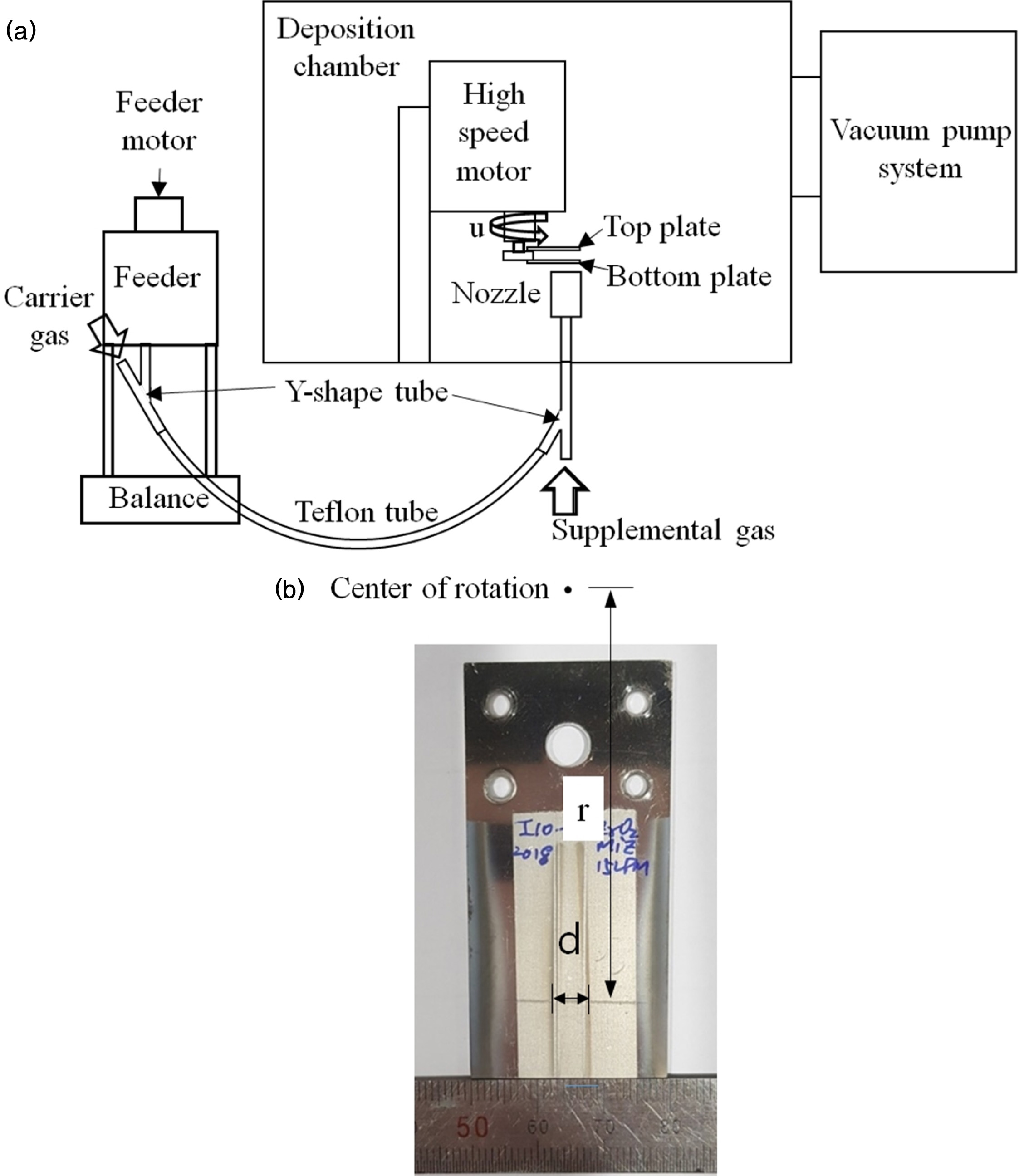
(SCM) according to the previous report [14]. Fig. 1(a) shows SCM apparatus
schematically. Two 1 mm thick stainless steel plates, bottom and top plate were
attached to a rotor. The top plate was the impact surface for the sprayed
granules and was positioned above the bottom plate at a distance, L of 10 mm
from the bottom plate. The bottom plate had slit dimensions of 35 mm ´ 0.8 mm and was positioned above the
spray nozzle which had a throat with dimensions of 35 mm ´ 0.8 mm. The nozzle throat was
aligned to the slit of the bottom plate so that granules ejected from the
nozzle passed through the slit of the bottom plate and impacted with the top
plate. Due to the high rotation speed (u) of the plates, collision with the top
plate occurred off the projection line of the slit of bottom plate. By rotating
the plate-assembly clockwise and counter clockwise, two lines were formed on
the top plate as shown in Fig. 1(b). Experiments were performed
as follows. Rotor assembly with the two plates were clamped to a high speed
motor and placed 2 mm off the nozzle. Rotor assembly, high speed motor and
nozzle were contained in a vacuum chamber called as deposition chamber. The
nozzle was connected to the outlet of a Y-shape tube with outside diameter of
9.525 mm as shown in Fig. 1(a). Granules from the feeder were carried by either
air or He and were introduced to one inlet of the Y tube. The other inlet of Y
tube was for supplemental gas which was also either air or He. After the
granules were poured into the feeder, the deposition chamber was evacuated by
vacuum pump system consisting of a filter, a rotary pump and a booster pump.
When vacuum level reached 6.5 Pa, the high speed motor was powered on to rotate
the plates at 9,000 rotation per minute (rpm). Then, both carrier gas and
accelerating gas were supplied. The carrier gas flow rate/supplemental gas flow
rate values are in liters per minute (LPM) were either 5/10 or 5/30. Each gas
flow rate was controlled by a mass flow controller (EL-Flow F-202AV,
Bronkhorst, AK Ruurlo, Netherlands). Since the MFC was calibrated for air, a
conversion factor of 1.454 was applied for flowing He [15]. After the gas flow
rates became stable, the feeder was powered on to allow zirconia granules to
flow into the carrier gas. Granules were sprayed for about 15 min for each
rotational direction. After spraying in both directions, the vacuum was broken
and the plates were removed from the rotor assembly. The distance between the
two lines (d) formed on the top plate and distance from center of rotation (r)
were measured as shown in Fig. 1(b). From these values the granule velocity was
calculated according to the equation based on assumption that traveling time of
the granule from the bottom plate to the top plate is the same as half that
taken for the plates to move d by rotation. Therefore, granule velocity in m/s
= πruL/(15,000d) where r, u and L are 52.5 mm, 9,000 rpm and 10
mm, respectively.
Zirconia
film deposition and characterization
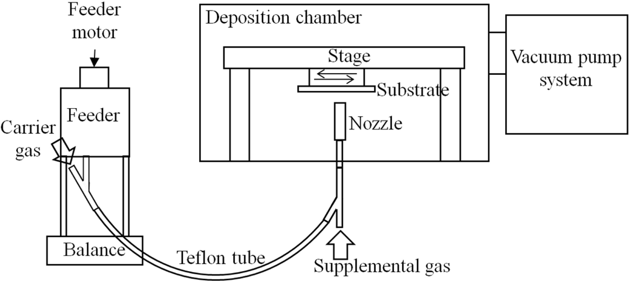
Fig. 2 shows a schematic diagram of the experimental
apparatus. In order to measure the granule consumption directly, the granule
feeder was placed on top of an electronic balance (HJ-33K, Shinko Denshi Co.,
Ltd., Tokyo, Japan) which can measure up to 33 kg with accuracy of 0.1 g. About
50 g of monoclinic zirconia granules were poured in the feeder. The mass of the
feeder with granules, Teflon tube between feeder and nozzle, and nozzle were
measured. A soda lime glass plate with dimensions of 60 ´ 90 ´ 2
(thickness) mm3 was used as a substrate. The mass of the glass
substrate was measured with a precision electronic balance (AG135,
Mettler Toledo, Greifensee, Switzerland) which can read 0.1
mg up to 101 g. The substrate surface was cleaned with ethanol and affixed to a
stage shown in Fig. 2 by using a scotch tape. Tape was placed to avoid any
interference with deposition. The stand-off distance from nozzle was 10 mm.
After the deposition chamber was evacuated to 6.5 Pa, the
stage with substrate traversed a distance of 65 mm back and forth at 200
mm/min. Both carrier gas and supplemental gas were on. Gases used and their
flow rates were the same as those used for granule velocity measurements. When
the gas flow rate was stabilized, the pressure in the chamber was recorded.
Then, the feeder was activated and the granules were delivered to
the nozzle. Granules were further accelerated by the
supplemental gas. Deposition was performed for about 400 s. The sample
surface was cleaned with laboratory tissue and compressed air. Then, the mass
of the sample was measured with a precision electronic balance for obtaining
the film mass. The mass of the feeder, tube and nozzle after the experiment was
also measured by the electronic balance for obtaining granule consumption.
DE was calculated as the film mass divided by amount of
granules consumed. Each experiment was repeated 4
times and the average value and standard deviation were calculated. Ultrasonic
cleaning was performed on some of the samples by immersing them in ethanol for
30 min in order to test film stability and adhesion. Both top surface and
fracture surface of the sample was observed with SEM. XRD was carried out for
phase analysis of the sample.
A three pass experiment was
carried out by using a double-side carbon tape as substrate that travelled only
once in order to examine smashed granules on the substrate. Carrier gas flow
rate and supplemental gas flow rate were 5 LPM and 10 LPM, respectively. All
the other experimental conditions and procedures were the same as described
above.
|
Fig. 1 Schematic diagram of apparatus for granule velocity measurements (a) and the top plate after the experiment (b). |
|
Fig. 2 Schematic diagram of GSV system. |
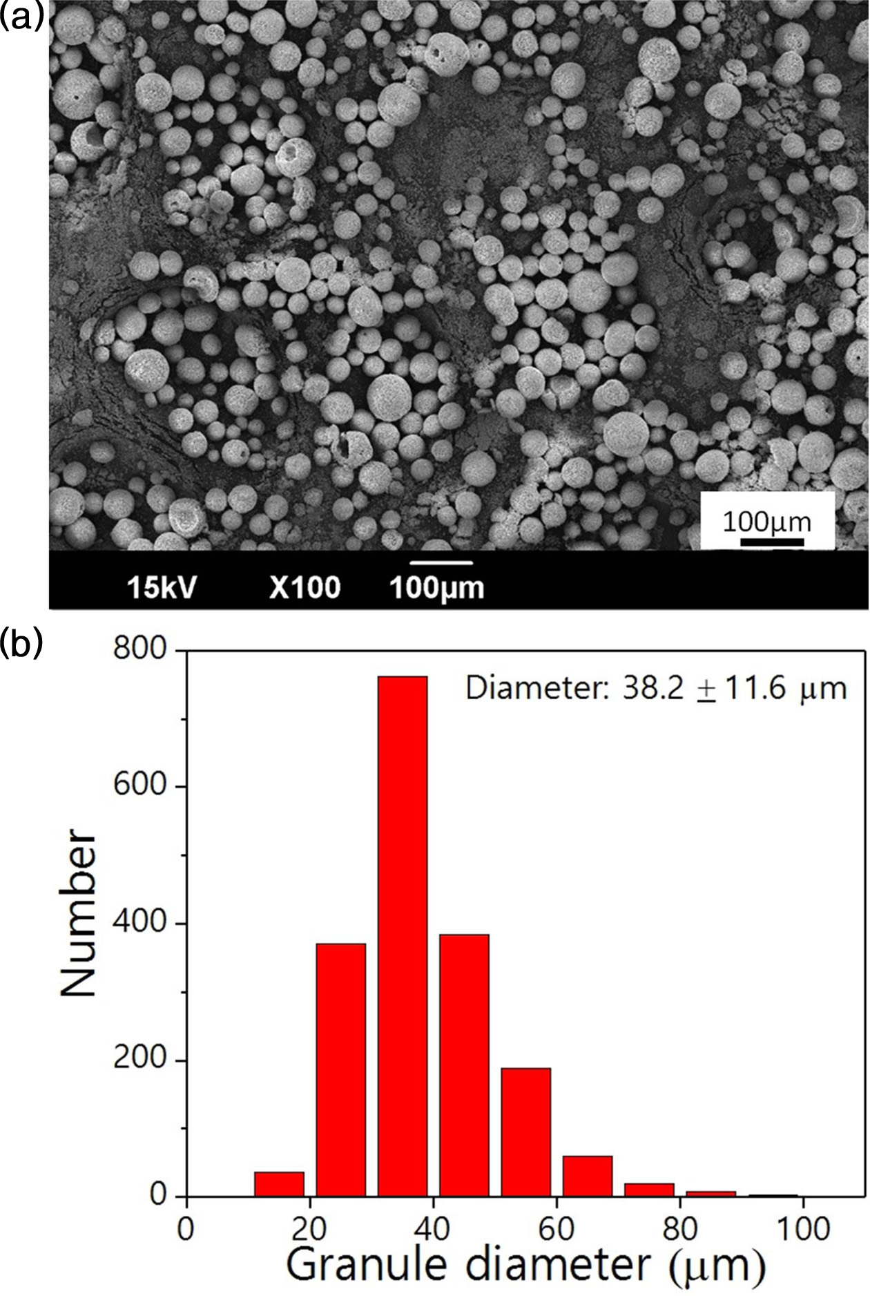
Fig. 3(a) and (b) show an SEM image of monoclinic zirconia
granule feedstocks used for this study and their size distribution,
respectively. They were in a flowable spherical shape and their average size
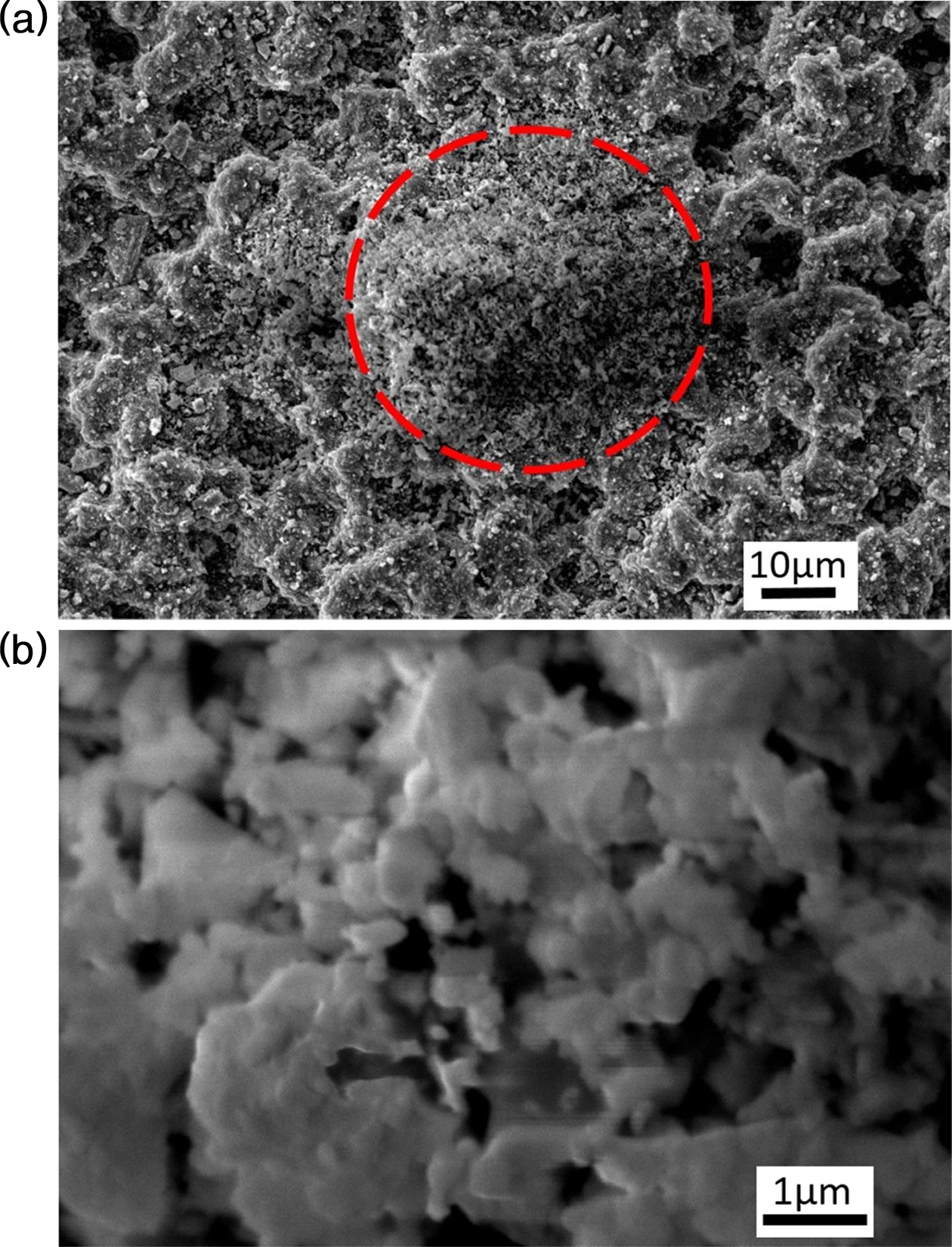
was 38.2 μm. Fig. 4(a) and (b) are SEM micrographs of double-side
carbon tape after the three-pass experiment. From Fig.
4(a) it is evident that the granule remained intact during transport through
the nozzle and was squashed up impingement with the substrate as indicated by
the dashed circle. Fig. 4(b) shows that particles much finer than the average
particle size (1.1 μm) as well as bigger ones that collided with a
substrate. Akedo reported that very small particles evaded the substrate by
following the flow of the carrier gas due to their small mass.
However, even those very small particles can reach the substrate by being
agglomerated in a granule. In other words, more particles including very small
ones possibly impinged upon the substrate in GSV than in ADM, possibly giving
rise to higher DE.
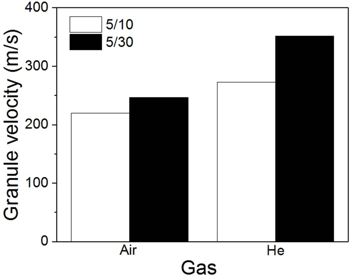
Fig. 5 shows granule velocity according to the
experimental conditions. Higher gas flow rate (5/30) resulted in higher granule
velocity than lower gas flow rate (5/10) for both gases (i.e. air and He).
Also, the granule velocity was higher when He was used than when air was used.
The granule velocity results were consistent with Akedo’s report on ADM [2]. We
also measured chamber pressure during the experiments. When the two gas flow
rates were 5/10 and 5/30, the pressures were 20 Pa and 46 Pa, respectively.
They were the same for both air and He, suggesting the gas conversion factor
(1.454 for He) was reasonable. According to Ning et al. and Ozdemir et al., He
exhibited more than twice the gas velocity at the exit of their cold spray
nozzles due to high specific heat ratio as well as the small molecular weight
compared to nitrogen, which has similar physical property to air [16, 17]. They
described that higher gas velocity resulted in higher
particle velocity for He than for N2. Even though
the gas velocity at the nozzle exit was not measured in our study, the velocity
of He was suspected to be higher than that of air as in the case of cold spray.
The higher granule velocity in the He case shown in Fig. 5 may be mainly due to
higher gas velocity of He than that of air. It is worth mentioning that the
granule velocity increased only by 12% and 29% as air flow rate and He flow
rate were increased more than twice, respectively. According to our previous
report, the pressure difference between the feeder and deposition chamber (ΔP)
increased as the gas flow rates were increased [10]. However, the increment was
very small compared with that of the gas flow rates. ΔP was considered as a
major driving force for acceleration of granules. Therefore, the small increase
in granule velocity due to the gas flow rate increase may be explained in part
by the small ΔP. One way to increase the granule velocity may be the use of
vacuum pumps with a large pumping capacity to decrease pressure in the
deposition chamber and thereby increasing ΔP.
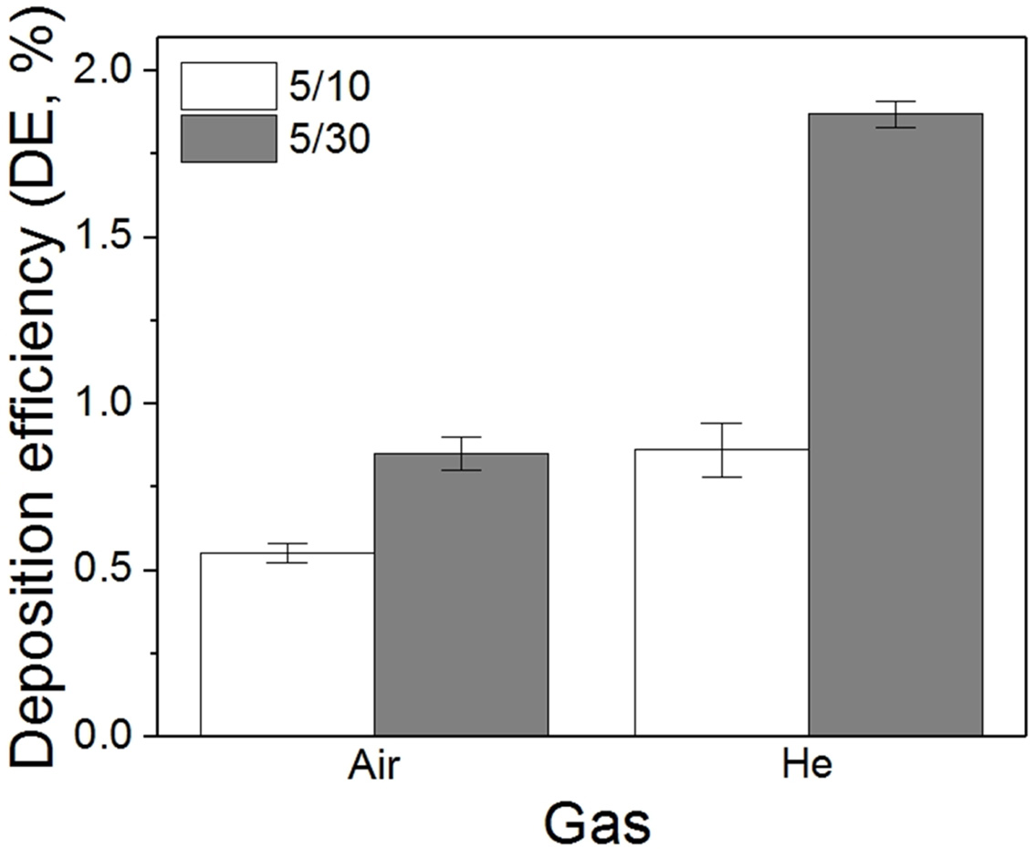
Fig. 6 shows DE of monoclinic zirconia granules according
to the experimental conditions. Unlike most cases found in the literature, DE
was obtained from direct measurement of granule consumption and the film
weight. DE values obtained were 0.55±0.03%, 0.85±0.05%, 0.86±0.08% and
1.87±0.04% for 5/10 air, 5/30 air, 5/10 He and 5/30 He, respectively. It is
worth noting here that higher gas flow rate resulted in higher DE and that He
was more effective in improving DE than air. DE shows a similar
trend with granule velocity shown in Fig. 5, only exaggerated in
terms of the gas flow rate effect and gas species effect. It is suggested that
the granule velocity played an important role in DE. Fuchita et al. used a
similar zirconia powder to the one used for this study and nitrogen which has
similar physical property to air [4]. DE value roughly estimated
from their report (0.65%) was not much different from those shown for air (0.55% and
0.85%) in Fig. 6 although the details of deposition variables were different. We postulate that the DE might be
improved by spraying granules because granules are able to include very small
particles in the deposition process that would otherwise have been carried away
by the gas flow. In other words, more particles are able to participate in film
formation by minimizing the amount of particles evading the substrate due to
their small size. However, the above two DE values (0.55% and 0.85%) were not
high enough to mark an advantage from using granules compared with DE values of
ADM calculated from the report of Fuchita et al. [4]. It also implies that only
very small fraction of collisions of the particles with the substrate were successfully
contributed to the film formation. Fig. 6 shows that He is an attractive gas
for improving DE. Although not many DE values can be found in the literature,
1.87% was much higher than 0.65% estimated from Fuchita’s report on deposition
of the very similar monoclinic zirconia [4] and may be the highest DE of
ceramic films by room temperature spray of ceramic particles or granules like
ADM or GSV to the best of our knowledge.
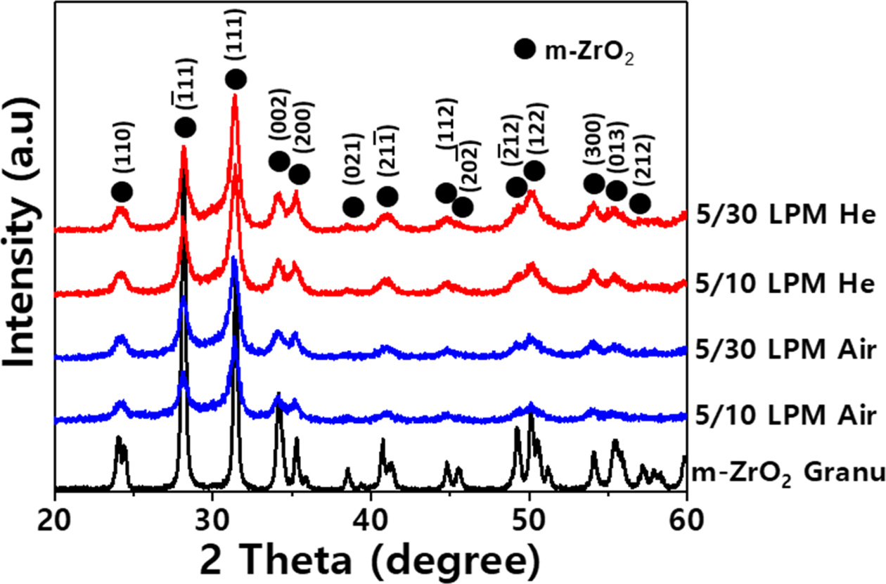
Fig. 7 shows XRD patterns of the zirconia. Both the feed
material (monoclinic zirconia granules) and deposited
films exhibited monoclinic zirconia phase without any other detectable phase.
Patterns of the films had broadened peaks with weaker intensity than those of
the granules. Weak intensity of the film might be related to small thickness of
the film. Peak broadening of the film
implied that the film contained nano-scale
crystallites with defects as reported previously [18]. Weight loss of the
films after a 30-minute ultrasonic
cleaning were 2.7%, 2.2%, 1.2% and 1.3% for the films deposited under 5/10 air,
5/30 air, 5/10 He and 5/30 He conditions, respectively. The weight loss was
small enough to consider the films as being well-formed and the change in mass
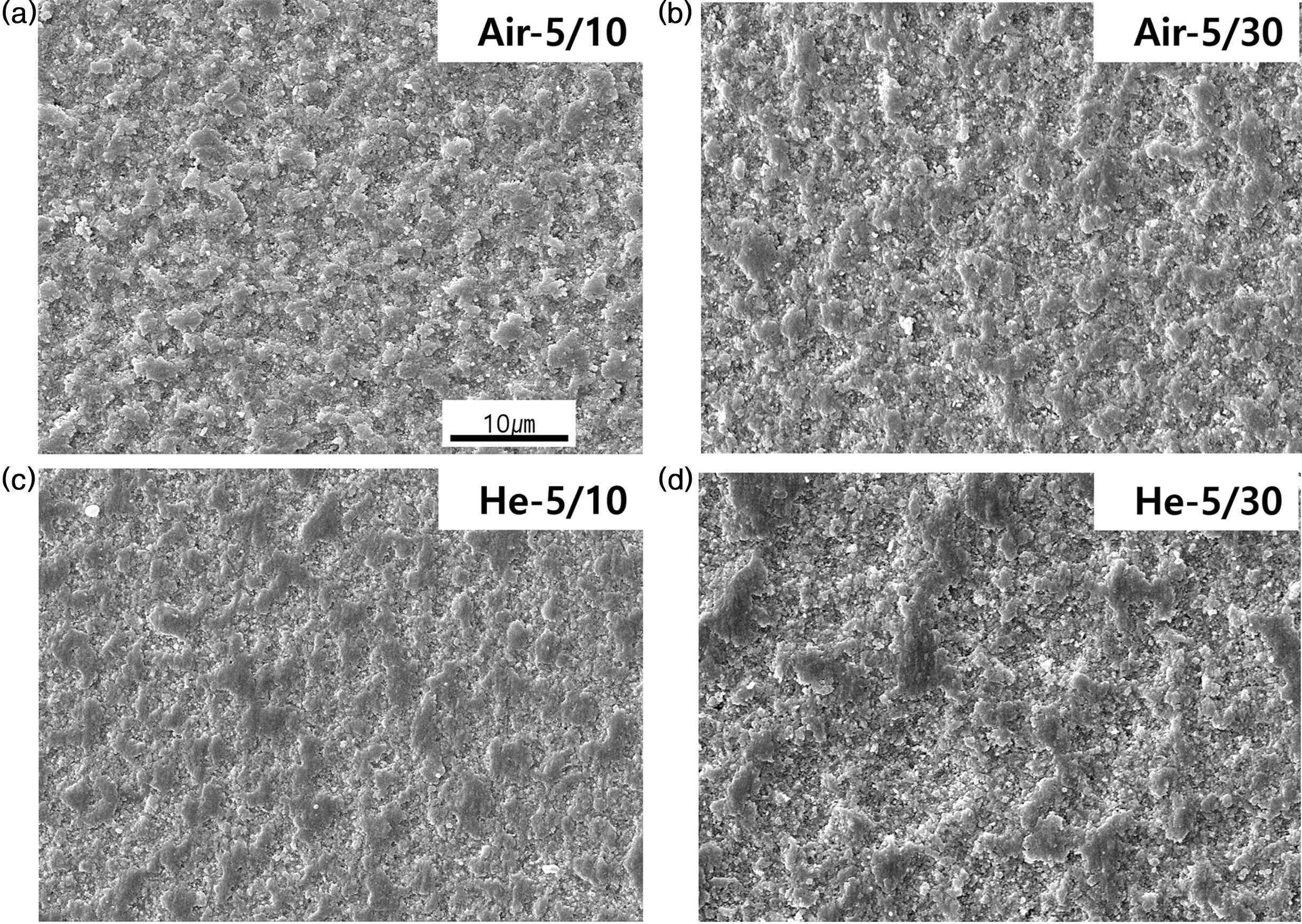
did not appreciably affect our calculation of DE. Fig. 8(a)-(d) show top
surfaces of the zirconia films. They show typical features of ADM or GSV
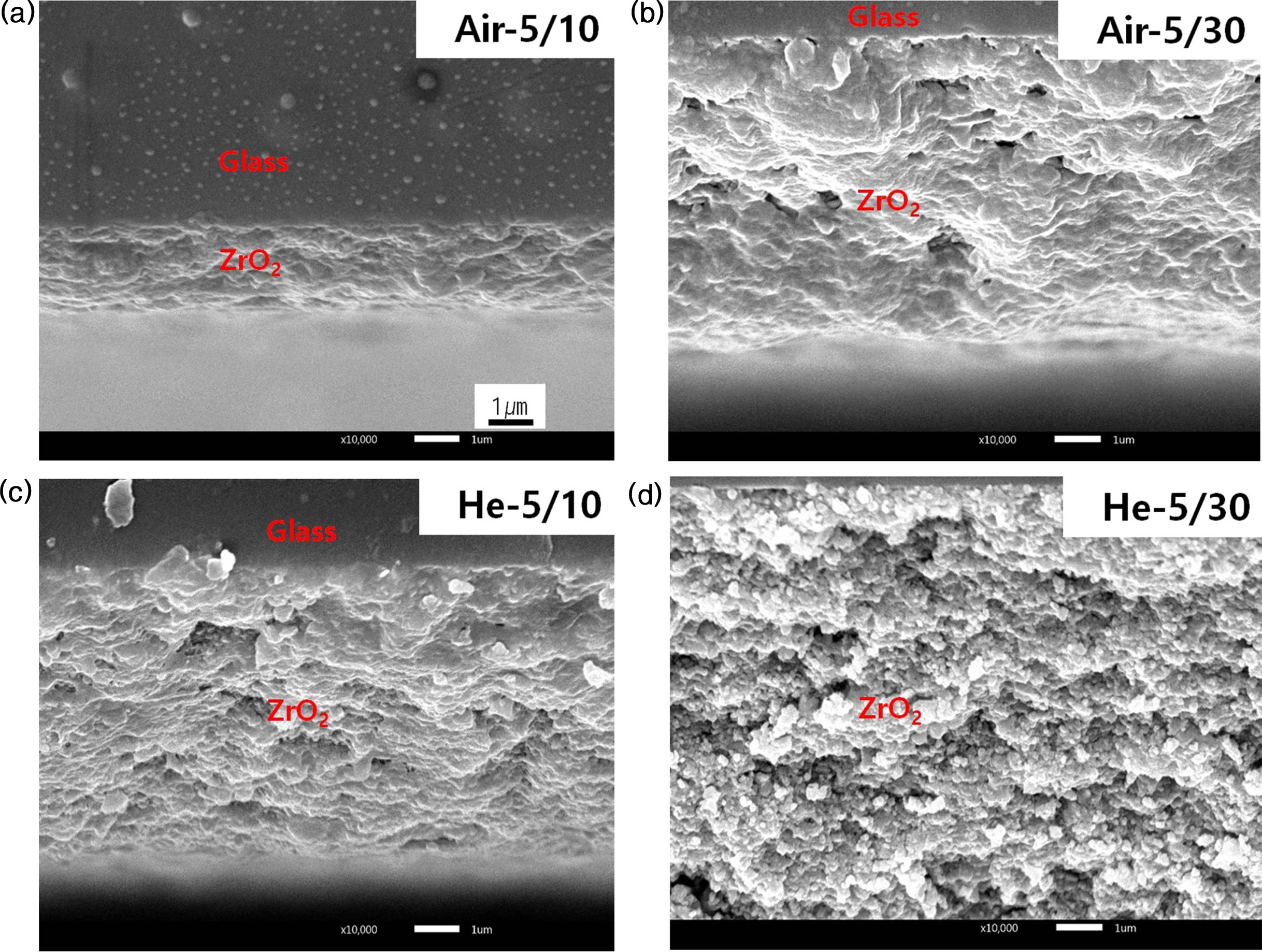
ceramic films; ridges and valleys. Fig. 9(a)-(d) are SEM micrographs of cross
section obtained by cleaving the films. The film thicknesses were consistent
with DE shown in Fig. 6 assuming the granule consumptions were similar for all
the experiments. The films appear quite dense and inter-granular bonding looked
strong even though there were some pores.
|
Fig. 3 SEM micrograph of monoclinic zirconia granules (a) and
their size distribution (b). |
|
Fig. 4 SEM micrographs of double-side carbon tape after the
single pass experiment; (a) low magnification and (b) high
magnification. |
|
Fig. 5 Granule velocity obtained by slit cell method; 220 m/s, 247
m/s, 273 m/s and 352 m/s for 5/10 air, 5/30 air, 5/10 He and 5/30
He, respectively. |
|
Fig. 6 DE according to the experimental conditions. |
|
Fig. 7 XRD patterns of monoclinic zirconia granules and zirconia
films deposited by GSV. |
|
Fig. 8 SEM micrographs of top surface of samples; (a) 5/10 air, (b) 5/30 air, (c ) 5/10 He and (d) 5/30 He. |
|
Fig. 9 SEM micrographs of fractured edge surface; a) 5/10 air, (b) 5/30 air, (c ) 5/10 He and (d) 5/30 He |
Deposition efficiency of monoclinic zirconia film prepared
by granule spray in vacuum was obtained from direct measurements of granule
consumption and the film weight. It increased as flow rate of process gas was
increased possibly due to increased kinetic energy. He was more effective as
the process gas for improving DE than air. The highest DE value achieved by
using He was 1.87% which was more than double the value obtained by using air
and may be higher than any other reported DE of ceramic films by room
temperature spray of ceramic particles or granules like ADM or GSV to date.
Since granule velocity varied in the same way as DE, we conclude that DE is
closely related to the granule velocity. Zirconia films deposited by GSV
retained the crystalline phase of the starting powder and peak broadening of
their XRD patterns was observed as in the other ADM ceramic
films. Morphology of the films observed from the top surface and the
fracture surface revealed that well-adhered dense zirconia films were
deposited.
This work was supported by the Pukyong National University
Research Abroad Fund in 2017 (C-D-2017-0964).
- 1. J. Akedo, J. Thermal Spray Tech. 17 (2008) 181-198.
-

- 2. J. Akedo, J. Am. Ceram. Soc. 89 (2006) 1834-1839.
-
- 3. D. Hanft, J. Exner, M. Schubert, T. Stöcker, P. Fuierer, and R. Moos, J. Ceram. Sci. Tech. 6 (2015) 147-182.
-
- 4. E. Fuchita, E. Tokizaki, E. Ozawa, and Y. Sakka, J. Ceram. Soc. Japan. 118 (2010) 948-951.
-
- 5. B.-D. Hahn, D.-S. Park, J.-J. Choi, J. Ryu, W.-H. Yoon, K.-H. Kim, C. Park, and H.-E. Kim, J. Am. Ceram Soc. 92 (2009) 683-687.
-
- 6. S.D. Johnson, E.R. Glaser, F.J. Kub, and C.R. Eddy, J. Vis. Exp. 99 (2015) e52843.
-
- 7. T. Reimann, J. Töpfer, S. Barth, H. Bartsch, and J. Müller, Int. J. Appl. Ceram. Technol. 10 (2013) 428-434.
-
- 8. K. Mihara, T. Hoshina, H. Takeda, and T. Tsurumi, J. Ceram. Soc. Jpn. 117 (2009) 868-872.
-
- 9. J.-H. Park, D.-S. Park, B.-D. Hahn, J.-J. Choi, J. Ryu, S.-Y. Choi, J. Kim, W.-H. Yoon, and C. Park, Ceram. Int. 42 (2016) 3584-3590.
-
- 10. Y. Park, D.-S. Park, S. D. Johnson, W.-H. Yoon, B.-D. Hang, J.-J. Choi, J. Ryo, J.-W. Kim, and C. Park, J. Euro. Ceram. Soc. 37 (2017) 2667-2672.
-
- 11. K. Naoe, K. Sato, and M. Nishiki, J. Ceram. Soc. Jpn. 122 (2014) 110-116.
-
- 12. S.D. Johnson, D. Schwer, D.-S. Park, Y. Park, and E.P. Gorzowski, Surf. Coat. Tech. 332 (2017) 542-549.
-
- 13. J. Eichler, U. Eisele, and J. Rödel, J. Am. Ceram. Soc. 87 (2004) 1401-1403.
-
- 14. J. Akedo, J. Vac. Soc. Jpn. 54 (2011) 118-127.
-
- 15. https://www.omega.fr/green/pdf/FMA_GAS_CONV_REF. pdf
- 16. X.-J. Ning, J.-H. Jang, and H.-J. Kim, Appl. Surf. Sci. 253 (2007) 7449-7455.
-
- 17. O.C. Ozdemir, C.A. Widener, D. Helfritch, and F. Delfanian, J. Therm. Spray Tech. 25 (2016) 660-671.
-
- 18. B-D. Hahn, K.-H. Ko, D.-S. Park, J.-J. Choi, W.-H. Yoon, C. Park, and D.-Y Kim, J. Kor. Ceram. Soc. 43 (2006) 106-113.
 This Article
-
2020; 21(5): 571-578
Published on Oct 31, 2020
- 10.36410/jcpr.2020.21.5.571
- Received on Apr 23, 2020
- Revised on Jul 6, 2020
- Accepted on Jul 16, 2020
Services
- Abstract
introduction
materials and method
results and discussion
conclusions
- Acknowledgements
- References
- Full Text PDF
Shared
Correspondence to
- Chan Park
-
Department of Materials Engineering, Pukyong National University, Busan 48547, South Korea
Tel : +82 516296360
Fax: +82 516296353 - E-mail: chanpark@pknu.ac.kr
Clean-Energy Research Institute(CRI), Hanyang University, 222, Wangsimni-ro, Seongdong-gu, Seoul, 04763, Korea
E-mail: jcpr@hanyang.ac.kr