


- A novel method: mixed matrix membrane – An overview
R Umapriyaa,*, J Rohanb, S Manisha Vidyavathyc, Thenmuhild and G Arthanareeswarane
aDepartment of Chemical Engineering, Erode Sengunthar Engineering College, Perundurai, Tamilnadu 638407, India
bDepartment of Chemical Engineering, Adhiyamaan Engineering College, Hosur, Tamilnadu 635109, India
cDepartment of Ceramic Technology, Alagappa College of Technology, Anna University, Chennai, Tamilnadu 600025, India
dDepartment of Ceramic Technology, Alagappa College of Technology, Anna University, Chennai, Tamilnadu 600025, India
eDepartment of Chemical Technology, National Institute of Technology, Trichirapalli, Tamilnadu 620015, India
The development of India into
a modern country is slow but the population growth is rapid. Pure air, water
and soil are the three important things for a day to day life in the current
scenario. Pure form of these three is must. Nowadays many water resources,
soils and air in the environment are polluted due to massive increase in
population growth, industrialization and modern Urbanization. The heavy metals,
dyes, pesticides etc., are mainly polluting the water bodies. In current
scenario the world is in the need of treating water bodies, wastewater and sea
water to reduce the water scarcity level. All wastewater and water treatment
processes possess at least one separation process in the treatment units.
Membrane separation process is playing a main role in the treatment process. In
this study, the different types of conventional and advanced treatment
processes were discussed. Membrane treatment techniques, Types of membranes,
materials which can be used for membrane preparation, advantages and
disadvantages of each materials, performance of organic membrane (polymeric
membrane), performance of inorganic membrane (ceramic membrane) and membrane
fabrication methods were also discussed in this study. To overcome the
drawbacks, the new innovative idea was derived and discussed.
Keywords: Polymeric membrane, Inorganic membrane, Mixed matrix membrane
General
Population growth rate of the world was reported as a 75
million annually [1]. The world population was reported as 3.4 billion in 2009
and it was grown by 30% approximately between the year 1990 and 2010 according
to the UN population statistics. If this situation continues,
there is the possibility of having the population as 6.3
billion in 2050 [1]. In this, India’s growth rate was reported as 350 million.
Parallel to this population growth, the world is moving with
rapid industrialization and
urbanization too. Apart from the basic requirements (Food, Cloth
and Shelter), pure air, water and soil are also added in the basic requirements
due to this rapid growth of world. In most of the cases the air and water
purification are considered as a major problem. The need of deriving pure fresh
water from different water sources and domestic and industrial
effluent is increased due to this growth. This paper
discusses the new innovative membrane process for treating the water and
suggests new material and method for the membrane preparation.
Water and wastewater Treatment
Due to the water scarcity and pollution, the water and
wastewater should be treated and reused. The treatment generally consists of
the following conventional treatment methods [2].
1. Primary Treatment (Mixing,
Equalization, Screening and Clarification)
2. Secondary Treatment (Sedimentation or
Clarifloc- culation,
Filtration and Advanced treatment methods like
adsorption, Ion exchange, and membrane filtration).
3. Tertiary treatment (Nitrogen and
phosphorous removal treatment methods and disinfection, etc.)
Initially the wastewater is mixed and equalized to get a
homogeneous solution. The water from the equalizer is fed to the screen chamber
for removing large size materials and followed by oil trap for removing oil,
fat and grease. This water is then subjected to sedimentation
tank or flash mixing chamber based on the intensity of the solids.
Coagulants (such as lime, alum, polyelectrolyte, etc.) are
added with the water in the flash mixing tank. Then it is processed through
Clariflocculator to create high densed flocs. This floc contained
water is sent to a settling tank for the settlement of the impurities
(suspended matters) present [2].
Most of the processes in chemical industry involve at
least one separation or purification to remove foreign matters or to recover
the water [3]. The separation process is generally divided into as
equilibrium governed process and rate governed process.
Equilibrium governed process includes distillation, absorption,
Adsorption, drying etc., Most of the membrane-based processes are rate governed
process. It includes Osmosis, Reverse Osmosis, Dialysis, etc., These
processes are carried over by the
gradient of chemical potential (i.e., concentration gradient,
pressure gradient, temperature gradient and electrochemical potential gradient)
[3]. In this paper particularly membrane filtration was discussed.
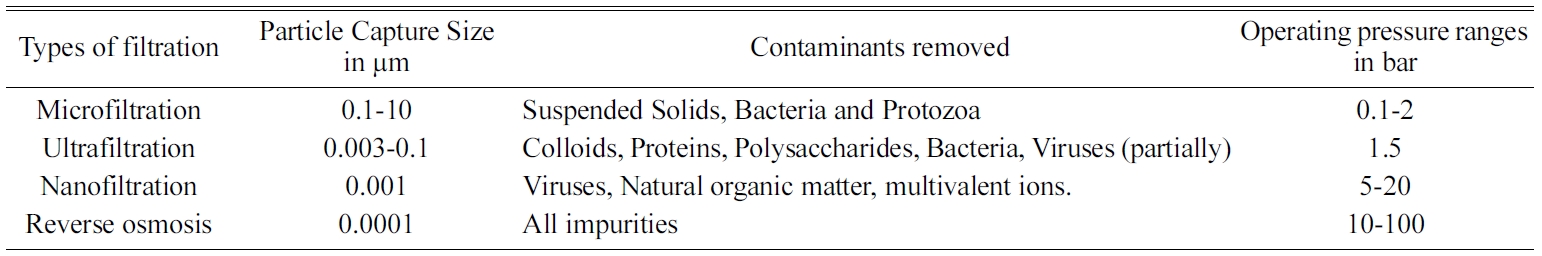
Table 1
Initially the membrane separation process was started in
laboratory scale. Later it started growing to the industrial pilot plant level
with proper technical and commercial requirements. The reasons to choose for
membrane technology are: fast process with short residence time, less component
specific [4]. The basic principle of Membrane processes are
the mechanisms of impaction, diffusion, electrostatic interaction, hydrophobic
property, and adsorption [5]. The transport selectivity of the
membrane, high efficiency, Low capital cost and operating cost, ease of
operation and lower energy requirements and low time for the
completion of processes are also the
main advantages of the membrane separation processes.
The gas separation and liquid separation by membranes is a growing field in the
current scenario [4, 5].
The wide research spectrum subjects to modulation and
improvement in search of better prototypes development.
Types
of membrane filtration
The main part or heart of the membrane process is nothing
but the membrane itself. To get the best efficiency in the removal, the
identification of the new membrane materials that can be with the expected requirements
is strongly growing in the current research field.
Generally, the criteria for selecting materials for membrane separation are too
difficult. Based on the purpose of utilization, the materials and pore size of
the membranes will be selected. Fig. 1 represents the average
pore size requirement for membranes for different water treatment processes
[6].
There are four main types of membrane system commonly used
in industry [7] based on pore size: (a) Microfiltration (MF) is
widely applied in particulate removal process and maintains degreasing. (b) Ultra filtration (UF) is generally
used for oil, water and emulsion separations; paint recovery; and the separation of
fats, oils or greases in the food industry. (c)
Reverse osmosis (RO) and (d) nanofiltration (NF) are used extensively for water
purification and desalination. Membrane Distillation is one of the developing
techniques to treat saline water [8, 9]. Fig. 2 shows the
differences of membrane system.
Materials
of membrane
Two types of materials are used generally in the membrane
preparation. First one is organic membrane (polymeric membrane) and the other
one is inorganic membrane (ceramic membrane). Membranes are made from different
materials based on the application. They are manufactured in different forms to
produce optimal hydrodynamic conditions for separation. Complete
systems comprise arrangements of modules and control systems
needed to integrate them into the various process configurations.
Polymeric membranes
Polymeric membranes are drawn the attention for its use in
many applications such as wastewater treatment, food
industries, etc., Due to its pore forming mechanism in a
straightforward manner, higher flexibility, low installation
cost and low manufacturing cost, the polymeric membrane
turned the attention. Some important criteria (good filtration flux, low energy
consumption) are considered in a selection of membrane to get a high quality
[10]. Though, polymeric membrane has many advantages, it has some challenges
such as relationship between selectivity and permeability and its resistance
for the membrane fouling [10].
Polymeric membranes are very competitive in both
performance and cost wise. The polymers must exhibit appropriate properties for
specific applications. They offer low binding affinity in case of biotechnology
applications. They show good fabrication properties for that fabricating
process. The polymeric materials used for making into membrane are
cellulose acetate, cellulose nitrate, polyamide, polysulfone,
polycarbonate, poly (ether sulfone), polyimide, poly (vinylidene fluoride),
polyacrylonitrile (PAN), polyphenols, polytetrafluoro- ethylene, etc., These
membranes have many applications such as effluent filtration,
dialysis, pervaporation, gas separation, etc., [11].
Advantages of polymeric membranes:
• They have excellent heat resistance and
chemical compatibility [12],
• They have good mechanical properties and high modifying
abilities [73-78]. Disadvantages of polymeric membranes
• It suffers from biofouling, mineral
scaling, abrasion, metal oxide fouling,
• It has low stability and low rejection [6, 13].
- They have low surface hydrophilicity, low
porosity and low permeability [73].
Ceramic membranes
Ceramic membranes are used in water treatment, fermentation
industries, food industries, dairy industries, paper
industries and petrochemical industries. The out promising
advantages of ceramic membranes are extended lifetime,
constant quality, excellent separation ability, reduced energy requirements,
high permselectivities. The disadvantages of ceramic membranes are higher
density, higher production cost, lower surface area per unit volume,
complicated synthesis process [16].
The materials used for the preparation of ceramic
membranes are alumina, zirconia, silica and titania [24]. Ceramic membranes
consist of three layers.
Inner porous support layer-provides good mechanical
strength. Intermediate layer-coated upon support layer and has lower pore size.
Top layer-separation takes place Based on structure. Ceramic membranes can be
classified as porous and dense membranes. The porous membranes may
be symmetric or asymmetric. Asymmetric configuration gives high
permeability property [23]. Ceramic membranes are prepared in various geometric
configurations – plate and frame, tubular, capillary, hollow fibre [19].
Advantages of ceramic membranes [14]
1) They possess extremely high chemical, thermal,
mechanical and physical stability.
2)
Long working life.
3)
Good separation characteristics.
4)
Ecologically friendly
5)
No additives are required
6)
No phase transformation
7)
Running costs can is less
8)
They have high abrasion resistance.
Disadvantages
of ceramic membrane [14]
1)
Production cost is little high.
2)
Low membrane surface area.
3)
High density when compared with polymers.
4)
Fabrication process is complicated
Mixed matrix membranes
To overcome the drawbacks of polymeric membranes,
the novel technique with high stability and high ions rejection was developed.
Mixed Matrix Membranes (MMM) consist of organic and
inorganic particle phases. In this
continuous phase is polymeric phase and dispersed phase is
inorganic particles.
Mixed matrix membranes have
higher selectivity, permeability. MMMs improve the mechanical [51], thermal
[52], magnetic [53], and electrostatic [54]. So generally, to improve
hydrophilicity in the polymeric membrane surface modification, hydrophilic
polymer coatings, grafting, composite structure formations can be done. In the
recent days the MMM is widely used in the gas separation process, textile
effluent treatment, oil removal, desalination, etc..
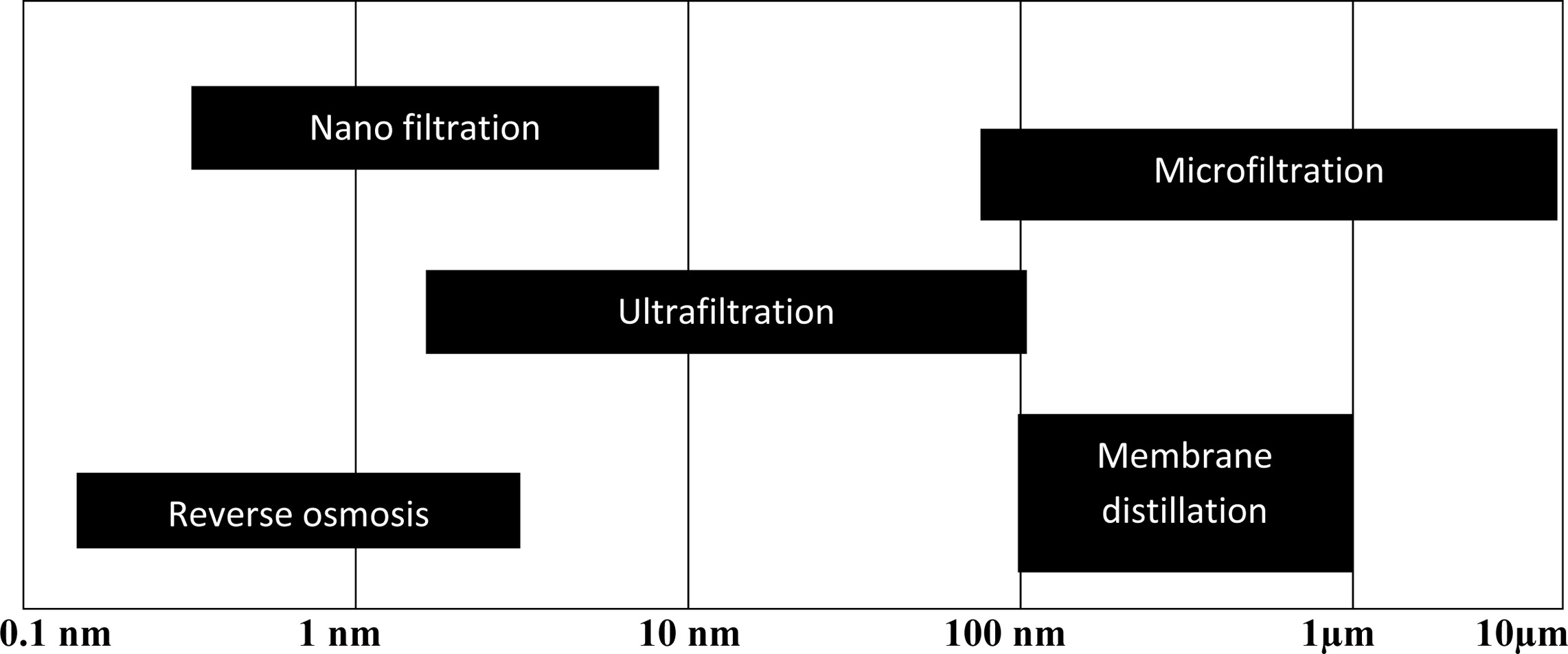
|
Fig. 1 Average pore size of the membranes used in different membrane process. |
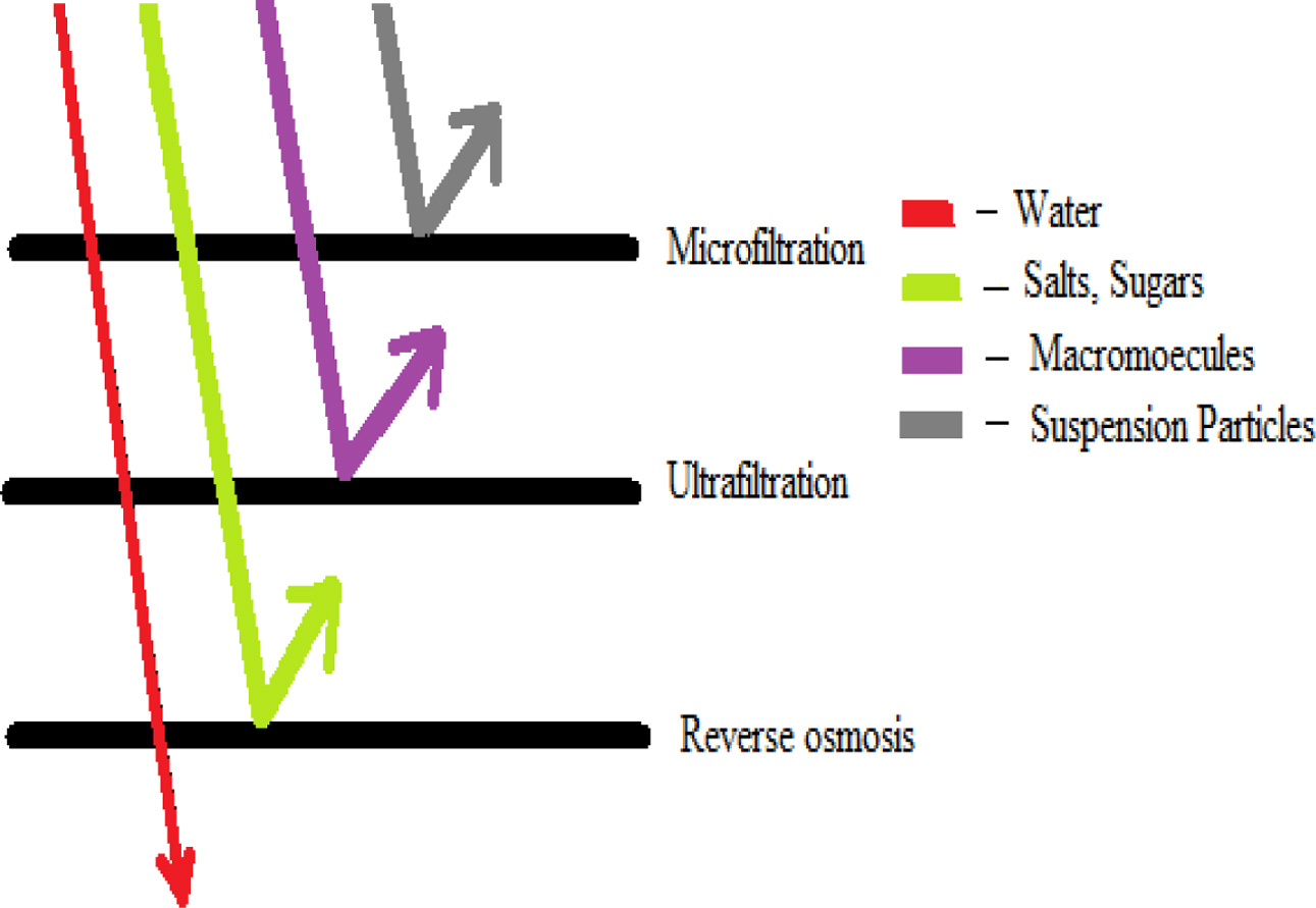
|
Fig. 2 Use of membrane systems to separate of different sized molecules |
Polymeric
membrane
The selection of method for the fabrication of membrane is
highly dependent on the type of polymer and the geometry of the membrane to be
designed. The methods commonly used for fabrication are [6]
• Phase inversion
• Interfacial polymerisation
• Stretching
• Track – etching
• Electrospinning
Phase inversion
This process is also known as de-mixing process. Here,
the homogeneous polymer solution is transformed from liquid
state into solid state in a controlled manner [13]. This transformation
involves five ways [55]:
a) Immersion precipitation
b) Thermally induced phase separation
c) Evaporation induced phase separation
d) Vapour induced phase separation
Among these immersion precipitation and thermally induced
phase separation methods are the most commonly used methods [11, [56].
Interfacial polymerization
It is a common method for the fabrication of thin-film
composite (TFC) membranes for nano-filtration and reverse osmosis. The first
interfacially polymerised thin-film composite membrane was developed by Cadotte
et al. [57] and they are used for many RO and NF applications [58].
Stretching
This method is suitable to produce microporous membranes
which are commonly used in applications such as microfiltration,
ultrafiltration, etc., This process is first developed in 1970s. This process
does not use any solvent. The polymer is heated above its melting point and
extruded into thin films. Then it is stretched to make it porous [59-61].
Track-Etching
Here, irradiation of a nonporous polymeric membrane
using energetic heavy ions. This leads to the formation of damaged tracks
linearly in the irradiated polymeric film. This technique is more
advantageous for its control on the pore size distribution [62].
Electrospinning
It is a new technique where a drop of polymer is made into
a liquid jet by applying a high potential between the droplet and the ground
collector. The droplet gets converted into liquid jet when the potential
becomes greater than the surface tension of the droplet [63-65].
Ceramic
membrane
The steps involved in the synthesis of ceramic membranes
are, suspension preparation, forming and heat treatment.
There are various methods available for ceramic membrane
synthesis. They are slip casting, sol gel, dip coating, extrusion, pressing,
anodic oxidation, solid state process, pressing, tape casting and freeze
casting [16]. The required membrane structures and the application
are the major considerations for the selection of appropriate membrane
preparation method.
Slip casting method
The most common method for ceramic membrane fabrication is
the slip casting method. Fig. 3 shows the schematic diagram of slip casting
method. The major disadvantages of this method are that the control of wall
thickness is difficult, and it requires long time. The mold is filled with
powder suspension and the diffusion of solvent into pore takes place. Hence gel
formation occurs by precipitation followed by rapid condensation to prevent the
penetration of particles into pores [17, 18]. Some of the membranes prepared by
this method are alumina [19], zirconia [20], and perovskite [21], BaCo0.7Fe0.2Nb0.1O3-δ
[22].
Sol gel
Sol gel is an important method for synthesis of ceramic
membranes. This method gives a good control over the pore size and pore size
distribution. They are of two categories – colloidal route and polymer route
[16].
In colloidal route, the hydrolysis of dissolved metal
alkoxide in alcohol is done by addition of acid or water.
Maintaining the precipitate formed as a hot solution for long
time results in stable colloidal solutions. It is then cooled and coated on the
support surface followed by sintering process [23, 24]. His route is
mainly used for the synthesis of silica [25, 26] and alumina membranes [27].
In the polymeric route, partial hydrolysis of metal
alkoxides dissolved in alcohol is done by addition of excess of water to for
inorganic polymer. The polymer formed is coated on the surface, dried and
sintered [28]. This procedure is adopted for the manufacturing of
titania [29] and zirconia membranes [30].
Dip coating
Thin membranes can be obtained by this method [16].
This method involves the dipping of the supports in the sols followed by drying
and calcining. This method is utilized in the preparation of silica membranes
[25], alumina membranes [33, 34], titania [30], zirconia [35].
Extrusion
It is importantly used for production of ceramic tubes. A
paste is formed by mixing raw materials. A mould is extruded from the paste,
dried, calcined and sintered. The preparation of porous alumina ceramics by
extrusion method is carried out using poly vinyl acetate as pore former. The
remaining solvent is evaporated [36]. Usually,
the diameter of the membrane formed is greater than 2 mm
and the thickness is greater than 0.5 mm [16]. Ba0.5Sr0.5Co0.8Fe0.2O3-d
hollow fibre membrane synthesis by extrusion method involves EDTA
–citrate complex as starting powders [37].
Freeze casting
This process involves the formation of slurry with ceramic
powders, dispersant and deionised water. Then, it is
poured in the mould and solidified. After complete solidification, specimens
are lyophilized and dried. Finally, they are sintered. This procedure was
adopted for the synthesis of yttria – stabilized zirconia
membranes [38]. Freeze casting method is also
employed to fabricate porous tubular mullite membranes
[39]. Maintenance of constant cooling rate in this method produces porous alumina
membrane with improved mechanical properties [22].
Mixed
matrix membranes
According to recent study, wet phase inversion method was
suggested to prepare the MMM [73, 74, 78]. Common procedure for preparing MMM
is:
1. Polymer solution was prepared by dissolving the
required amount of polymer in N- methyl-2-pyrrolidone (NMP) solvent.
2. Mixture should be stirred for 24 h at 60 oC
to get a homogeneous polymer solution.
3. Desired amount of Inorganic material dispersed
in NMP will be added.
4. Mixture should be stirred for 24 h at 60 oC
to get a uniform dispersion of inorganic material in polymer solution.
5. This casting solution will be deposited on a
clean glass plate pasted with adhesive material on both sides.
6. Glass plate will be allowed at room temperature
for 30s and then it will be immersed in the non solvent bath until the complete
phase inversion.
7. After complete phase inversion, the membrane
will be peeled, washed thoroughly with water.
8. Clean membrane will be stored in
slightly chlorinated distilled water.
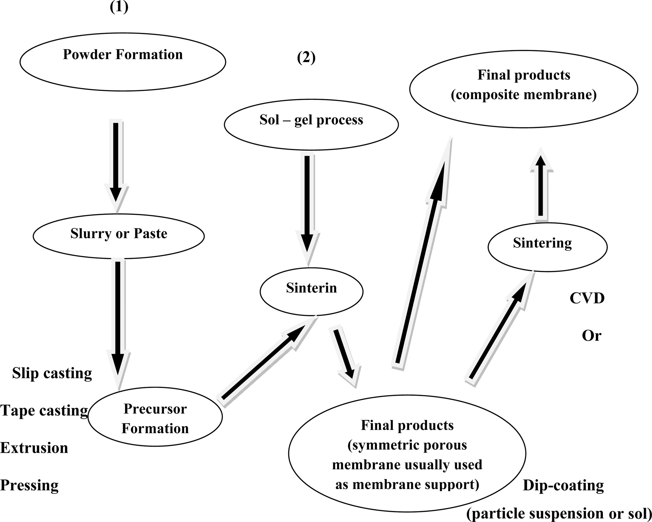
|
Fig. 3 Slip casting method. |
Polymeric
membrane
Polyamide membranes being hydrophilic material do not
require a wetting agent. This membrane is mainly used for microfiltration and
reverse osmosis [66].
Polyimide has excellent heat resistance; chemical
compatibility and resistance over wide range of pH are widely used
in high temperature fuel cells and separation membranes
[74].
Polysulphone membranes were more commonly used in the
process of ultrafiltration of wastewater because of its
mechanical robustness and chemical and structural stability.
Since it is a low hydrophilic in nature, it is modified by
blending it with SiO2, ZrO2, and TiO2 which
are hydrophilic nanoparticles to increase its hydrophilic properties.
This blending process improved the separation performance
of the membrane, its thermal and chemical resistance
and its adaptability to wastewater environments [67].
PVDF (Polyvinylidene fluoride) membranes were used in
wastewater purification and desalination in many trials. It has the advantage
of good separation performance and mechanical stability. Qi Zhang et al. [68],
fabricated membrane with PVDF and PVC (Polyvinyl Chloride) by phase
inversion method. The polymer ratios were varied as 1%, 5%, 10%, 20%, and 50%
and its influence on the structure and performance of the membranes were
investigated. Among these, the membrane with 5% of PVC had high porosity, high break
strength and water flux. The membrane with small wt% of PVC
had better performance and increased the applications of PVDF [68].
Cellulose acetate is one of the first polymer membrane
used for separation process and is used in both RO and UF
applications. This material is generally used because it is
naturally available, has high mechanical strength and it has high hydrophilic
property. R. Saranya et al. [93], used the composite membrane of chitosan and
cellulose acetate membrane for the removal of copper ions from the wastewater.
It showed a retention of 81.03% for copper ions. The results of the
studies carried out with Cellulose acetate is the one of the most important
polymeric material [69]. It is having high hydrophilicity
and easy processability. But it was having excessive
fouling, lower pH, and thermal stability.
Ceramic
membranes
Silica membranes
Silica membranes showed higher permeability with small
molecules. Silica membranes can be prepared with low defect concentrations [31,
32]. They were employed for energy efficient separation processes
under industrial conditions. They were also
used for dehydration and hydrogen process [40]. When compared to other
oxides such as alumina, zirconia and titania, silica involves easier
preparation as ultra or microporous thin layers. Unsupported silica membranes
prepared from the sol obtained by hydrolysis with acid catalyst and
condensation of tetra ethyl ortho silicate followed by calcination is
microporous in nature and showed a significant permeability to helium and
hydrogen. At the same time, the permeability of N2, Ar, O2,
C3H6, C3H8, nC4H10,
i-C4H10 was very small. At 303 K, hydrocarbon permeation
was 2 times that of helium [26]. Hydrophobic nature is
being observed from the silica membrane prepared by the repeated dip coating of
supported γ-alumina membranes in silica sol
solution followed by drying and calcining. Hydrophobicity was due to the added
methyl tri ethyl silicate. The obtained membrane has a pore diameter of 0.7 nm
and a thickness of 60 nm. The hydrophobicity was 10 times more than that of
ordinary silica membrane [31]. A double layered silicate
coated membrane on γ-alumina was synthesized by sol gel
dip coating using surfactant template silica as intermediate layer. Cheong et
al., 1999 stated that the dual layered membrane showed
improvement in flux and stability [25]. Sols were prepared from tetra
ethoxy silane and octyl-,
dodecyl-
and octadecyltriethoxysilane to fabricate silica membranes on γ-alumina
coated α-alumina tube. Micropores were obtained in size range of 0.3-0.4 nm
when calcined at 600 °C. Mesopores formed during the gelation step [42].
Alumina membranes
Alumina membranes have been used for both liquid and
gaseous separations [43]. The alumina membranes had high resistance to
temperature, pressure, oxidation, solvents, hot acids and caustic solutions
[44]. They are back flushable and can be sterilized by steam [19].
It has an excellent thermal, chemical and mechanical strength
[17]. Non supported mesoporous γ-alumina membrane
prepared from boehmite sols were with a pore radius of
2.2. nm when calcined at 600 °C. Membranes with α-alumina support were
with a pore radius of 2.5 nm [27]. Supported -alumina membrane were prepared by
dipping into boehmite sols also observed that the layer thickness decreased
with increase in the pore size of the support [33]. Mesoporous γ-alumina
membranes on cordierite honeycombs were prepared by the method of dip
coating into boehmite with addition of HNO3 to bring
the pH to 4.0 [34]. Preparation of alumina membranes from aluminium
secondary butoxide reveals that the transition of 7-AlOOH to 7-Al2O3
takes place at 390 °C [33]. γ-alumina
nanofiltration membranes with pore diameter greater than 5 nm
were prepared from boehmite at low sintering temperature of
about 540 °C. Boehmite can be obtained by the precipitation
of complete hydrolysis of aluminium alkoxide [45].
Titania membranes
Titania membranes have unique structure and surface
properties. Titania membranes show high resistance towards corrosion at strong
acidic pH [46]. Titania membranes when calcined at high temperatures results in
phase transformation to anatase and hence the structure collapses. Sekulic et
al., 2004 reported that the membranes were of high chemical stability at wide pH ranges [29]. Titania
membranes exhibit higher permeability to
propylene. Asymmetric titania membranes
were prepared by wang et al., 2008 from stable titania suspensions with a pore
size in the range of 0.1-0.12 microns
[46]. He used sol gel technique for the synthesis of titania nanofiltration membranes. Membrane with top layer of anatase
– TiO2 fired at 300 °C is with low crystallinity and at a pH of
2, the molecular weight cut off increased to 800 from 200 [35]. Microporous
titanic membranes layers of pore size lesser than or equal to 0.8 nm are
synthesized on mesoporous γ-alumina and titania/zirconia coated substrates by
polymeric sol gel route [29]. Non supported titania membranes were prepared by
dip coating in colloidal dispersions of titania. Supported titania membranes
are prepared by slip casting with the same solution. The membrane is of 3-6
micron thick and with an average pore diameter of 3-4 nm [30].
Zirconia membranes
Zirconia membranes show higher rejection rates towards
polyvalent ions and lower rejection rates towards monovalent
ions [47]. Zirconia membranes possess superior stability in aqueous solutions
[48]. At low and high pH values, zirconia membranes were preferred due to its
chemical stability under these conditions [35]. Yttria stabilized the zirconia
membranes prepared from polymeric sol gel method with zirconium
tetra-n-propoxide and yttrium nitrate. The chelating agent used here is
acetylacetone [49]. Yttria stabilized zirconnia membranes prepared by freeze casting
method has a compressive strength of 23.57 to 63.86 MPa and they exhibit non
catastrophic failures [38]. Nanofiltration zirconia membranes prepared by sol
gel technique from synthesized zirconia sols were having average particle size
of about 8.6 nm [50]. Membranes with molecular weight cut
off less than or equal to 300 for nanofiltration and per
evaporation purposes were produced with α-alumina support prepared by slip
casting method, yttria doped zirconia interlayer and
zirconia top layer prepared by dip coating method [35].
MMM-desalination
The freshwater resources are getting dried. Water
desalination has been increased and got an important role in supplying
freshwater [70-72]. In the todays trend, the polymeric membrane is preferred
for the filtration more than the conventional treatment to get better salt
rejection and high-water flux. But in all the polymeric
membrane processes the water flux was stated as low due
to low permeability. Currently, polymeric, ceramic and mixed matrix membranes
are used in desalination. Polymeric membranes are widely used in this field.
Bio-fouling, poor thermal and chemical stability are the main challenges for
the polymeric membrane. Ceramic membranes show excellent thermal
and chemical stability that make them a possible alternative to be used in
water desalination process.
Combination of polymer with inorganic such as Graphene,
carbon nanotubes and various nano particles such as
silica, titania and zirconia MMM were produced to improve
the performance of membrane. Low loading rate, poor dispensability,
hydrophilicity are the major issues in the MMM. In the membrane filtration
polysulfone based membranes were used. It had good resistance over the wide
range of pH. But it was having the hydrophobic nature. By improving the
hydrophilic nature of the membrane, the productivity will be increased.
The blending of the polymer with hydrolysed poly
isobutylene-alt-maleic anhydride is the promising method to improve the
hydrophilicity [3]. High salt rejection and good hydrophilicity can be achieved
by blended polymer membrane with surface midified poly isobutylene-alt-maleic
anhydride [4]. Functionalised inorganic material in the membrane
preparation also gives the increased hrdrophilicity [5, 6].
Mainly polysulfone (Psf), polyether sulfones, poyimides, polyamides were used
in the MMM preparation [74].
Graphene oxide, Titania, silica and zirconia nanoparticles
Iron III oxides were used with polymeric membrane to improve the hydrophilicity
[2-5]. Ionic strength and pH of the solution also can induce agglomeration
between nanoparticles. These materials absorb very easily the hydroxyl groups
(OH-)
and they have high surface area and a very good antifungal and antibacterial
materials.
Bo Feng et al., 2017 used nanohybrid graphene oxide (GO)
and polyimide (PI) in the MMM preparation [74]. B.M Ganesh et al., 2013 used
the GO and Psf (polysulfone) for the MMM preparation [73]. Javed aslam
et al., 2013 used polyether sulfone with iron oxide
nanoparticles [78]. A derivative of graphene containing oxygen
rich functional groups leads the high hydrophilicity and high
water permeability in the membrane. In this GO has the strong interaction with
polymer chain. Mechanical strength, stability, water permeability, antifouling and salt rejection can be improved.
Wet phase inversion method was used
for the MMM preparation in this work.
B.M Ganesh et al., 2013 [73] used the GO and Psf in the
MMM to enhance the hydrophilic nature of the membrane. Wet phase inversion
method is used for the membrane preparation. He mentioned that the salt
rejection depends on pH. If the pH increases, the salt rejection
will be increased. Polysulfone based membranes are used
because of its excellent heat resistance, Chemical compatability and have good
resistance over the wide range of pH. Blending Psf with hydrolysed poly
isobutylene-alt-maleic anhydride increases the hydrophilicity. GO is preferred
due to its high surface area. GO is used due to its
outstanding electron transport and
mechanical properties, hydrophilic and pH sensitive behavior. In
this after GO doping the salt rejection was increased.
Polyether sulfone is used by javed aslam et al., 2013 for
the MMM preparation for desalination processes [78]. PES has
high glass transition temperature, thermal and chemical
stability. In this he doped the PES with iron III oxide nanoparticles. 15% Fe3O4
membrane gives the highest pure water flux, 10% Fe3O4
provides 10% salt rejection.
MMM
– Dye removal from textile industry effluent
Among the several separation techniques (impaction,
diffusion, adsorption and electrostatic interaction) [5], the
dye component of the textile effluent can be removed by
adsorption. The combination of adsorption and membrane
filtration is generally suggested for the textile effluent
treatment to enhance the membrane filtration. More number of research works are
carried out with activated carbon as an adsorbent material [85-88] due
to its large surface area [89] surface chemical deposition.
The effect of Activated Carbon on polysulfone and Polyether sulfone has been
studied thoroughly by Kusworo T.D. et al., 2010 [91] and Ballinas et al., 2004
[90] in their studies. With this Nanoparticles are also used
to improve the hrdophilic nature, filtration efficiency of polymeric
membrane. Nanoparticles of Iron oxide and Zero valent iron (ZVI) has high
surface area [92]. R.saranya et al., 2013 carried out the experiment with Cellulose
acetate+Activated carbon and Cellulose Acetate+Iron
Oxide combination [93]. They synthesised the different membranes and tested the filtration efficiency. High pure
water flux was achieved with the addition of 2.5%Activated Carbon and 0.5% Iron
oxide addition. They concluded that the addition of Activated carbon Activated
carbon influences the membrane permeability
and Iron oxide not. High rejection efficiency was obtained with no compromise in membrane permeability.
R.saranya et al., 2015 [94] used green synthesized zero
valent iron for the textile effluent treatment. They used ZVI for polymeric membrane
modification. The synergistic effect of permeation and adsorption
increases the use of ZVI/CA mixed matrix membrane for the textile
effluent treatment. Cellulose Acetate membrane was prepared with different mass
fractions of 0.5, 1.5 and 2.5 wt% of ZVI. Pure water permeability was increased
with 0.5% of ZVI nanoparticles addition. Physisorption was happened with this
filtration.
MMM
– Phenol and phenolic compounds removal
Most
of the chemical industries particularly petro- chemical industries produce phenol and
phenolic compounds which is very toxic and
carcinogenic [79, 80]. Continuous exposure to phenol gives eye irritation, skin
allergies, Mucous, headache, high blood pressure, liver and kidney damage.
Mixed matrix membrane is the better option
to remove Phenol from the effluent. RO membrane [81], Ultra filtration [82] and
nanofiltration are generally used in
the phenol removal. A novel technique, Nanoparticles doped MMM was nowadays
suggested as a better option to improve the removal percentage. Mixed matrix membrane of granular
alumina and Cellulose Acetate shows
flux enhancement [83]. Raka mukherjee 2014 [84] used doped alumina with
Cellulose Acetate Pthalate by phase inversion method. Various concentrations
membranes are prepared. 20 wt% alumina concentration membrane increases the
porosity and permeability.
MMM
– Proteins removal
Generally polymeric membrane with sulfone polymer
[75, 76], polysulfone, poly phenyl sulfone is used in the separation processes.
Polyethyl sulfone has the better properties than the polysulfone and polyether
sulfone [77]. Lawrence Arokiasamy dass et al., 2017 [78] fabricated the
sulfonated polyphenyl sulfone and Titania nanoparticles by phase inversion
method. With the 25.5% wt% the attained flux rate was high.
Thermal and mechanical properties also increased. Antifouling
properties of MMMs were enhanced. They concluded that fuctionalised
nanocomposite hollow fiber MMM will be the better promising membrane for the
proteins removal.
MMM
– Oilfield wastewater removal
Large quantities of oilfield wastewater are produced in
onshore and offshore exploitation. According to API 18bbl of
produced water were generated by US onshore operations
in 1995 [96]. Oilfield produced wastewater creates major environmental iisues [97].
Oil drilling produces large quantity of wastewater. Skimmer is the general
conventional treatment [98]. Polymeric and Ceramic membrane are used in the
removal of oil [99].
The necessity of the treatment of water was discussed in
this paper. In this paper, conventional treatment methods were discussed. Also,
particularly different types of membranes based on materials and pore size and
the factors affecting the Membrane processes were discussed. The mixed matrix
membranes are the combination of polymeric
and ceramic membranes. This MMM’s
hydrophilicity improving techniques were reviewed. Application of Mixed Matrix Membrane was also thoroughly
investigated. So that Mixed Matrix Membrane can be suggested as the novel
technique in the water and wastewater treatment. The future work can be carried
over with different material composition and with different inorganic particle
size composition to study the
performance behavior and other characteristics. Also, the work can be carried over with the derived inorganic and
organic materials from waste material so that the cost of the membrane will be
reduced. The wastes can also be recycled and reused.
- 1. J.-Bruinsma, in proceeding of Food and Agriculture Organisation of the United Nations Expert Meeting entitled How to Feed the world in 2050, Rome, Italy, (2009) 24-26
- 2. R. Umapriya, S.M. Vidhyavathy, G. Arthanareeswaran, and A. Vijayan, Int. J. Appl. Eng. Res. 10 (2015) 77-82.
- 3. S.-Ahuja, Sep. Sci. Tech. [4] (2003), 17-35
- 4. Hul, Jacob Peter vant, in “Membrane separation in Textile washing processes” (University of Twente Press, 1999) p.25-33.
- 5. H.J. Walther, S.D. Faust, O.M. Aly, Acta Hydroch. Hydrob. 16 (1998) 572.
- 6. B.S. Lalia, V. Kochkodan, R. Hashaikeh, and N. Hilal, Desalination 326 (2013) 77-95.
-

- 7. P. Aptel and C.A. Buckley, in “Water Treatment membrane processes” (McGraw-Hill, 1996) p.26.
- 8. M. Khayet and T. Matsumura, in “Membrane Distillation: Principles and Applications” (Elsevier, 2011) p.73.
- 9. E. Drioli and L. Giorno, in “Membrane operations: Innovative separations and transformations” (Wiley-VCH, 2009) p.80- 86.
-
- 10. L.Y. Ng, A.W. Mohammad, C.P. Leo, N. Hilal, Desalination 308 (2015) 15-33.
-
- 11. I. Pinnanu and B. D. Freeman, Formation and modification of polymeric membranes: overview. Desalination 278 (2011) 21-37.
- 12. J. Tong, L. Zhang, M. Han, K. Huang, J. Membr. Sci. 477 (2015) 1-6.
-
- 13. E. Drioli, L.Giorno, in “Membrane operations: Innovative separations and transformations” (Wiley-VCH, 2009) p.80-86.
- 14. L.C. Peng, in “Bimodal porous ceramic membrane via nano sized polystyrene templating: Syntesis, Characterisation and performanace evaluation” (Universiti Sains MalaysiaPress, 2008) p.75.
- 15. R.V. Kumar, A.K. Ghoshal, and G. Pugazhenthi, J. Membr. Sci. 490 (2015) 92-102.
-
- 16. S.K. Amin, H.A.M. Abdallah, M.H. Roushdy, and S.A. El-Sherbiny, Int. J. Appl. Eng. Res. 11[12] (2016) 7708-7721.
- 17. J.M. Benito, M. Conesa, A.F. Rubio, and M.A. Rodriguez, J. Eur. Ceram. Soc. 25[11] (2005) 1895-1903.
-
- 18. S. Schaffoner, L. Freitag, J. Hubalkova, and C.G. Aneziris, J. Eur. Ceram. Soc. 36[8] (2016), 2109-2117.
-
- 19. M. Barmala, A. Moheb, and R. Emadi, J. Alloys Compd. 485[1] (2009) 778-782.
-
- 20. F. Bouzerara, S. Boulanacer, and A. Harabi, Ceram. Int. 41[3] (2015) 5159 -5163.
-
- 21. D.D. Athayde, D.F. Souza, A.M.A. Silva, D. Vasconcelos, E.H.M. Nunes, J.C.D. Costa, and W.L. Vasconcelos, Ceram. Int. 42[6] (2016) 6555-6571.
-
- 22. Y. Zhang, L. Hu, J. Han, and Z. Jiang, Ceram. Int. 36[2] (2010) 617-621.
-
- 23. A.J. Burggraaf and L. Cot, in “Fundamentals of inorganic membrane science and technology-Chapter (7): Sol-gel chemistry and its application to porous membrane processing” (Elsevier Science, 1996) p.7.
-
- 24. A. Larbot, L. Gazagnes, S. Krajewski, M. Bukowska, and W. Kujawski, Desalination 168 (2004) 367-372.
-
- 25. H. Cheong, W.S. Cho, J.S. Ha, C.S. Kim, D.K. Choi, and D.S. Cheong, J. Alloys Compd. 290 (1999) 304-309
-
- 26. N.B. Nair J. Membr. Sci. 135[2] (1997) 237-243.
-
- 27. R.S.A. De Lange, Microporous Mater. 4[2] (1995) 169-186.
-
- 28. K. Li, in “Ceramic membranes for separation and reaction” (John Wiley & Sons, Inc., 2007) p.67.
- 29. J.J.E. Sekulic, T. Elshof, and D.H.A. Blank, J. Sol-Gel Sci. Technol. 31[1-3] (2004) 201-204.
-
- 30. V.T. Zaspalis, J. Mater. Sci. 27[4] (1992) 1023-1035.
-
- 31. R.M. de Vos, W.F. Maier and H. Verweij, J. Membr. Sci. 158[1] (1999) 277-288.
-
- 32. R.M. de Vos and H. Verweij, J. Membr. Sci. 143[1] (1998) 37-51.
-
- 33. A.F.M. Leenaars, K. Keizer, and A.J. Burggraaf, J. Mater. Sci. 19[4] (1984) 1077-1088.
-
- 34. S. Govender and H.B. Friedrich, Catalysts 7 (2017) 62.
-
- 35. T. Van Gestel, J. Membr. Sci. 214[1] (2003) 21-29.
-
- 36. T. Isobe, J. Eur. Ceram. Soc. 27[1] (2007) 61-66.
-
- 37. S. Liu and G.R. Georg, J. Membr. Sci. 246[1] (2005) 103-108.
-
- 38. K.H, Zuo, Y.-P. Zeng, and D. Jiang. Int. J. Appl. Ceram. Technol. 5[2] (2008) 198-203.
-
- 39. R. Liu, T. Xu, and C.-a. Wang, Ceram. Int. 42[2] (2016) 2907-2925.
-
- 40. L.H. Castricum, J. Mater. Chem. 18 (2008) 2150-2158.
-
- 41. M.A. Anderson, J.M. Gieselma, and Q. Xu, J. Membr. Sci. 39[3] (1988) 243-258.
-
- 42. K. Kusakabe, Sep. Purif. Technol. 16[2] (1999) 139-146.
-
- 43. C. Picard, A. Larbot, F. Guida-Pietrasanta, B. Boutevin, and A. Ratsimihety, Sep. Purif. Technol. 25[1] (2001) 65-69.
-
- 44. T. Masuda, H. Asoh, S. Haraguchi, and S. Ono, Materials. 8 (2015) 1350-1368.
-
- 45. L. Cot, A. Ayral, J. Durand, C. Guizard, N. Hovnanian, A. Julbe, and A. Larbot, Solid State Sci. 2[3] (2000) 313-334.
-
- 46. Y.H. Wang, X.Q. Liu, and G.Y. Meng, Mater. Res. Bull. 43[6] (2008) 1480-1491.
-
- 47. S. Benfer, U. Popp, H. Richter, C. Siewert, and G. Tomandl, Sep. Purif. Technol. 22 (2001) 231-237.
-
- 48. T. Tsuru, D. Hironaka, T. Yoshioka, and M. Asaeda, Sep. Purif. Technol. 25[1] (2001) 307-314.
-
- 49. X. Changrong, J. Membr. Sci. 162[1] (1999) 181-188.
-
- 50. H. Qi, J. Sol-Gel Sci. Technol. 62[2] (2012) 208-216.
-
- 51. A. Okada and A. Usuki, Mater. Sci. Eng. C3 (1995) 109.
-
- 52. J. W. Gilman, Appl.Clay Sci., 15, (1999), 31-49.
-
- 53. D. Godovski, Adv. Polym. Sci. 119 (1995) 135.
- 54. L.H. Li, J.C. Deng, H.R. Geng, Z.L. Liu, and L. Xin, Carbohydr. Res. 345 (2010) 994.
-
- 55. M. Mulder, in “Basic principles of membrane technology” (Kluwer Academic publishers, 1996) p.78.
- 56. N.F. Liu, A. Hashim, Y. Liu, M.R. Moghareh Abed, and K. Li, J. Membr. Sci. 375 (2011) 1-27.
-
- 57. J. Cadotte, R. Forester, M. Kim, R. Petersen, T. Stocker, Desalination 70 (1988) 77-88.
-
- 58. W.J. Lau, A.F. Ismail, N. Misdan, M.A. Kassim, Desalination 287 (2012) 190-199.
-
- 59. F. Sadeghi, presented in “Developing of Microporous poly- propylene by stretching” (Polytechnique Montreal, 2007) p.20.
- 60. W. Zhu, X. Zhang, C. Zhao, W. Wu, J. Hou, M. Xu, Polym. Adv. Technol. 7 (1996) 743-748.
-
- 61. K. Trommer, B. Morgenstern, J. Appl. Polym. Sci. 115 (2010) 2119-2126.
-
- 62. R.L. Fleischer, P.B. Price, and R.M. Walker, presented in “Nuclear tracks in solids, Principles and applications” (University of California Press, 1975) p.48.
- 63. J.A. Prince, G. Singh, D. Rana, T. Matsuura, V. Anbharasi, T.S. Shanmugasundaram, J. Membr. Sci. 397-398 (2012) 80-86.
-
- 64. B.S. Laila, E. Guillen-Burreiza, H.A. Arafat, R. Hashaikeh, J.membr.Sci. 428 (2013) 104-115.
-
- 65. R. Gopal, S. Kaur, Z. Ma, C. Chan, S. Ramakrishna, T. Matsuura, J.Membr. Sci. 281 (2006) 581-586.
-
- 66. A.K. Fard, G. McKay, A. Buekenhoudt, H.A. Sulaiti, F. Motmans, M. Khraisheh, and M. Atieh, Materials 11 (2018) 74.
-
- 67. H.L. Richards, G.L. Priscilla, Baker, and Emmanuel Iwuoha, J. Surf. Eng. Mater. Adv. Technol. 2 (2012) 183-193.
-
- 68. Q. Zhang, S. Zhang, Y. Zhang, X. Hu, and Y. Chen, Desalin. Water Treat. 51[19-21] (2013) 3854-3857.
-
- 69. A. Ghaee, M. Shariaty-Niassar, J. Barzin, T. Matsuura, and A.F. Ismail, Desalin. Water Treat. 57[31] (2015) 1-8.
- 70. M. Elimelech and W.A. Phillip, Science 333 (2011) 712-717.
-
- 71. M. Shanon, Nature 452 (2008) 301-309.
- 72. A. Cipollina, G. Micale, and L. Rizzuti, presented in “Seawater desalination: Conventional and renewable energy processes” (Springer, 2009), p.29.
- 73. B.M. Ganesh, M. Arun, Isloor, A.F. Ismail, Desalination 313 (2013) 199-207.
-
- 74. B. Feng, K. Xu, A. Huang, RSC Advances (2016) 164-169.
-
- 75. M. Sianipar, S.H. Kim, C. Min, L.D. Tijing, H.K. Shon, J. Ind. Eng. Chem. 34 (2016) 364-373.
-
- 76. H.G. Yuan, T.Y. Liu, Y.Y. Liu, X.L. Wang, Desalination, 379 (2016) 16-23.
-
- 77. A.W. Mohammad, Y.H. Teow, W.L. Ang, Y.T. Chung, D.L. Oatley-Radcliffe, N. Hilal, Desalination, 356 (2015) 226-254.
-
- 78. L.A. Dass, M. Alhoshan, J. Aslam, M.R. Muthumareeswaran, A. Figoli, and A.K. Shukla, Sep. Purif. Technol. 174 (2017) 529-543.
-
- 79. Canadian Environmental Protection Act, in “Priority Substances List Assessment Report: Phenol” (Health Canada, 1999) p.73.
- 80. R.J. Lifton, in “The Nazi Doctors” (Basic Books, 1986) p.254-268.
- 81. V.V. Goncharuk, D.D. Kucheruk, V.M. Kochkodan, V.P. Badekha, Desalination 143 (2002) 45-51.
-
- 82. M.K. Purkait, S. Das Gupta, S. De, Micellar, J. Colloid Interface Sci. 285 (2005) 395-402.
-
- 83. N.M. Wara, L.F. Francis, B.V. Velamakkani, J. Membr. Sci. 104 (1995) 43-49.
-
- 84. R. Mukherjee, S. De, Desalination 144 (2003) 51-59.
- 85. K.K.H. Choy, G. McKay, J.F. Porter, Resour. Conserv. Recy. 27[1-2] (1999) 57 - 71.
-
- 86. N. Kannan, M.M. Sundaram, Dyes Pigm. 51[1] (2001) 25-40.
-
- 87. C. Namasivayam, D. Kavitha, Dyes Pigm. 54 (2002) 47-58.
-
- 88. P.K. Malik, Dyes Pigm. 56[3] (2003) 239-249.
-
- 89. H. Marsh, F. Rodríguez-Reinoso, in “Activated Carbon” (Elsevier, 2006).
-
- 90. L. Ballinas, C. Torras, V. Fierro, R. Garcia-Valls, J. Phys. Chem. Solids. 65[2-3] (2004) 633-637.
-
- 91. T.D. Kusworo, A.F. Ismail, A. Mustafa, Budiyono, J. Sci. Eng. 1 (2010) 15-20.
- 92. W.X. Zhang, J. Nanopart. Res. 5 (2003) 323-332.
-
- 93. R. Saranya, Y. Lukka Thuyavan, and G. Arthanareeswaran, Journal Technology 20 (2013) 70-76.
- 94. R. Saranya, G. Arthanareeswaran, A.F. Ismail, D. Dionysios, and D. Paul, Journal Technology 26 (2015) 23-28.
- 95. K. Shams Ashaghi1, M. Ebrahimi, and P. Czermak, Open Environ. Sci. 1 (2007) 1-8.
-
- 96. API, in “Overview of Exploration and Production Waste Volumes and Waste Management Practices in the United States,” (ICF Consulting for the American Petroleum Institute, 2000) p.11.
- 97. Q. Li, C. Kang, C. Zhang, Proc Bio chem 40 (2005) 873-877.
-
- 98. F.E. Ciarapica, G. Giacchetta, presented in the Fifth Inter- national Membrane Science & Technology Conference, University of New South Wales, Sydney, Australia, (2003).
- 99. K. Shams Ashaghi, M. Ebrahimi, P. Czermak, Open Environ. Sci. 1 (2007) 1-8.
-
 This Article
-
2020; 21(3): 309-318
Published on Jun 30, 2020
- 10.36410/jcpr.2020.21.3.309
- Received on Oct 15, 2019
- Revised on Jan 4, 2020
- Accepted on Jan 17, 2020
Services
- Abstract
introduction
membrane filtration
membrane fabrication methods
polymeric, ceramic and mixed matrix membranes – an overview
mixed matrix membrane (mmm) – a novel separation technique - application
conclusion
- References
- Full Text PDF
Shared
Correspondence to
- R Umapriya
-
Department of Chemical Engineering, Erode Sengunthar Engineering College, Perundurai, Tamilnadu 638407, India
Tel : +91 6383421616
Fax: +91 9994302399 - E-mail: btech.priya@gmail.com
Clean-Energy Research Institute(CRI), Hanyang University, 222, Wangsimni-ro, Seongdong-gu, Seoul, 04763, Korea
E-mail: jcpr@hanyang.ac.kr