


- Fabrication and dielectric properties of CCTO/PF dielectric composites: CCTO with different particle size
Yang Zhaoa, Yuzhen Zhaoa, Yuhua Niub, Yongming Zhanga and Zongcheng Miaoa,*
aKey Laboratory of Organic Polymer Photoelectric Materials, School of Science, Xijing University, Xi’an, 710123, Shaanxi, People's Republic of China
bKey laboratory of Auxiliary Chemistry & Technology for Light Chemical Industry of Ministry of Education, Shaanxi University of Science & Technology, Xi’an, 710021, Shaanxi, People's Republic of China
Calcium copper titanate (CaCu3Ti4O12,
CCTO) particles with three types of particle size (CCTO–i, CCTO–ii,
CCTO–iii) are prepared by wet chemical method. And then the dielectric
composites based on CCTO particles and Phenol formaldehyde resin (PF) are
fabricated by mixing and mould pressing. This paper mainly studies the
microstructure and dielectric properties of CCTO/PF dielectric composites
(CCTO–i, CCTO–ii and CCTO–iii composites). XRD, FTIR and
SEM indicate that the CCTO particles are dispersed in the polymer matrix. In
addition, the effect of particle size on the dielectric properties of CCTO/PF
composites is also discussed. By comparing the CCTO/PF composites with
different particle sizes, it is found that the CCTO–i composite has a
high maximum dielectric constant and low loss at room temperature of 100 Hz,
while the CCTO volume fraction was 0.5 in the measurement frequency range,
which shows a very weak frequency dependence. On this basis, the CCTO–i
composite with relatively small particle size has excellent dielectric
properties, which may imply that the effect of interface will be changed by
smaller particle size.
Keywords: CCTO particles, PF, Particle size, Dielectric property
In the past decades, ceramic/polymer dielectric composites
exhibited high dielectric properties, good processability,
owing to the combination of the advantage of the
ceramic and polymer. The composite could be used in the fields of the high
density capacitors, embedded microcapacitors, artificial muscles and so on.
Recently, trends for these electronic devices require functionality, high-speed
performance, miniaturization and lower cost. Therefore, developing new types of
ceramic/polymer dielectric composites with relatively high dielectric
properties to satisfy requirement of miniaturization and multifunctionality of
electronic devices become an important subject in the area of the engineering
and technology [1-7].
Currently, among the ceramic/polymer dielectric composites,
the ceramics of BaTiO3 (BT), Ba0.6Sr0.4TiO3
(BST),
Pb(Zr, Ti)O3(PZT), and Pb(Mg1/3Nb2/3)O3–PbTiO3 (PMN–PT) exhibit relatively high
dielectric permittivity [8-11]. These ceramics would be used as inorganic
filler which mixed with the polymer matrix to form the ceramic/polymer
dielectric composites. However, such
ceramics always exhibit strong electro-
mechanical effects (such as
piezoelectric effect), which limits the reliability of the devices [12, 13].
Recently CaCu3Ti4O12(CCTO) with environment
friendly, giant permittivity, low loss tangent and better temperature stability
is introduced as ceramic fillers to further increase the dielectric constant of
the composites [14, 15]. What’s more,
Polyimide (PI), Poly (polyvinylidene–trifluoroethylene) (P(VDF–TrFE)), Epoxy resin,
Silicone resin, Polyvinylidene
fluoride (PVDF), and Polyaniline (PU), especially Phenol formaldehyde resin
(PF) that exhibit high mechanical strength, good insulativity and heat
resistance, are selected as polymer matrix [16-21]. To summarize, new types of
CCTO/polymer composite have been investigated. Dang et al. [22] fabricate a CCTO/PI
composite film (with 40 vol. % ceramic filler) with a dielectric permittivity
of about 49 at 100 Hz and room temperature, which is approximately 6 times
larger than that of pure PI. Babu et al. [23] report the permittivity of
CCTO/silicone resin composite is about 13 at 1 kHz and room temperature, which
would reach a maximum value by filling with CCTO volume fraction at 50 vol. %
and is about 4 times larger than silicone resin. Srivastava et al. [24] also
report the dielectric behaviors of CCTO/PVDF composite. The dielectric constant
of the CCTO/PVDF composite with 10 wt% of ceramic loading is about 8.2 at 1 Hz
and 300 K. However, the grain sizes of CCTO filler of these composites
mentioned above are prepared by several methods that could range from a few to
tens of micrometers. In some theoretical models [25], the large dielectric constant of CCTO/polymer dielectric
composite may contribute to the
morphology and the particle size of the ceramic powder. In addition, the
smaller CCTO particles exhibit the larger surface area, which also could
influence the dielectric properties. Therefore, ceramic/polymer composite containing different particle sizes
of CCTO that exhibit various dielectric properties, and then extraordinary properties of this
composite are obtained.
In this study, different sizes of CCTO particles are synthesized
by the sol–gel method, and then the composites are fabricated by
mixing and mould pressing. These composites, composed of CCTO
particles and PF matrix, are studied by varying the filler content and particle
size of the fillers. Finally, the variation of dielectric properties of CCTO/PF
dielectric composite with certain range of temperature and frequency are
measured.
Materials
Copper nitrate (99%), calcium nitrate (99%), tetrabutyl titanate
(≥98%), ethanol (≥99.7%), acetic acid (≥99.5%), ammonium
hydroxide (25%), phenol (99%), formaldehyde (37%),
oxalic acid (99.5%) and hexamethylenetetramine (≥99%) are
purchased from Sinopharm Chemical Reagent Co., Ltd., China. All
materials are used without further purifications.
Preparation
of CCTO particles
CCTO particle is synthesized by the sol–gel method as
follow: copper nitrate, calcium nitrate, and tetrabutyl titanate in the
stoichiometric ratio are dissolved ethanol separately.
The above solutions are mixed with continual stirring,
and then dilute ammonia solution is dripped dropwise into this solution to
adjust the pH to 1.0-2.0. The gel is formed at room temperature with several
hours. After that the powder is obtained by dried and ground, and then these
powder is calcined at 700, 800, 900 °C for 10 h to form the CCTO
particles which exhibit different particle size. These
particles are abbreviated as CCTO–i, CCTO–ii and CCTO–iii.
Preparation
of CCTO/PF dielectric composite
CCTO/PF dielectric composite are prepared by mixing
and mould pressing that the material contains different volume of CCTO–i,
CCTO–ii and CCTO–iii particles. The CCTO powders are
ultrasonically dispersed in mixed solution of phenol and formaldehyde for
several hours with stoichiometry (n(C6H5OH):n(HCHO)
= 1:0.85) in order to form a stable suspension. After that,
addition of oxalic acid as catalyst, the sample is obtained with polymerization
reaction for 3 h at 90 °C. The sample are filtrated, dried at 120 °C
in an oven and then ground into powders. Finally, these powders are well–mixed
and molded by hot pressing to obtain the dielectric composite. The final
samples with a disk shape are 15 mm in diameter and about 3 mm in thickness.
The CCTO/PF dielectric composites with the CCTO–i, CCTO–ii and
CCTO–iii particles are named as CCTO–i composite, CCTO–ii
composite and CCTO–iii composite respectively.
Characterization
techniques
The particle size distributions of CCTO–i, CCTO–ii
and CCTO–iii are measured by Laser Particle Size Analyzer. X-ray
diffraction patterns are obtained at room temperature with a Cu tube at 40 kV
and 100 mA by X-ray diffraction (XRD). The infrared spectra are recorded
in the 400-4000 cm-1
range by Fourier Transform infrared spectrometer (FTIR). The
morphology of composite is examined by
scanning electron microscopy (SEM).
For electrical measurement, the surfaces of CCTO/PF dielectric composites are
sputtered by silver paste to form electrodes. The permittivity and loss tangent
of these composites are measured by Agilent 4294A impedance analyzer in a
frequency range from 100 Hz to 1 MHz
over the temperature range of 25-75 °C.
Characterization
of CCTO particles
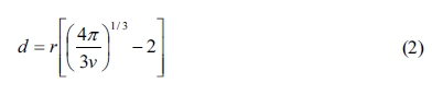
The X–ray diffraction patterns of CCTO particles (CCTO–i,
CCTO–ii and CCTO–iii) are shown in Fig. 1(a). The main
diffraction peaks of three kinds of CCTO particles are matched to the JCPDS
patterns of CaCu3Ti4O12 for identification
[26]. It shows that these particles have a cubic perovskite-related structure
(group: Im3). Some minor diffraction peaks of CaTiO3, CuO and TiO2
are detected in these particles, which are consistent
with previous literature [27]. CCTO–i particles with low calcining
temperature exhibit the lower diffraction
intensity peak than the CCTO–iii particles (the calcine temperature is
900 °C). And the FTIR spectrum of CCTO particle (CCTO–i) is shown in
Fig. 1(b). A peak appears at 458 and 571 cm-1
are attributed to the stretching vibration of Ti–O of CCTO–i particles.
From the XRD and FTIR, the CCTO particles are successfully prepared by the
sol–gel method with different calcine temperatures.
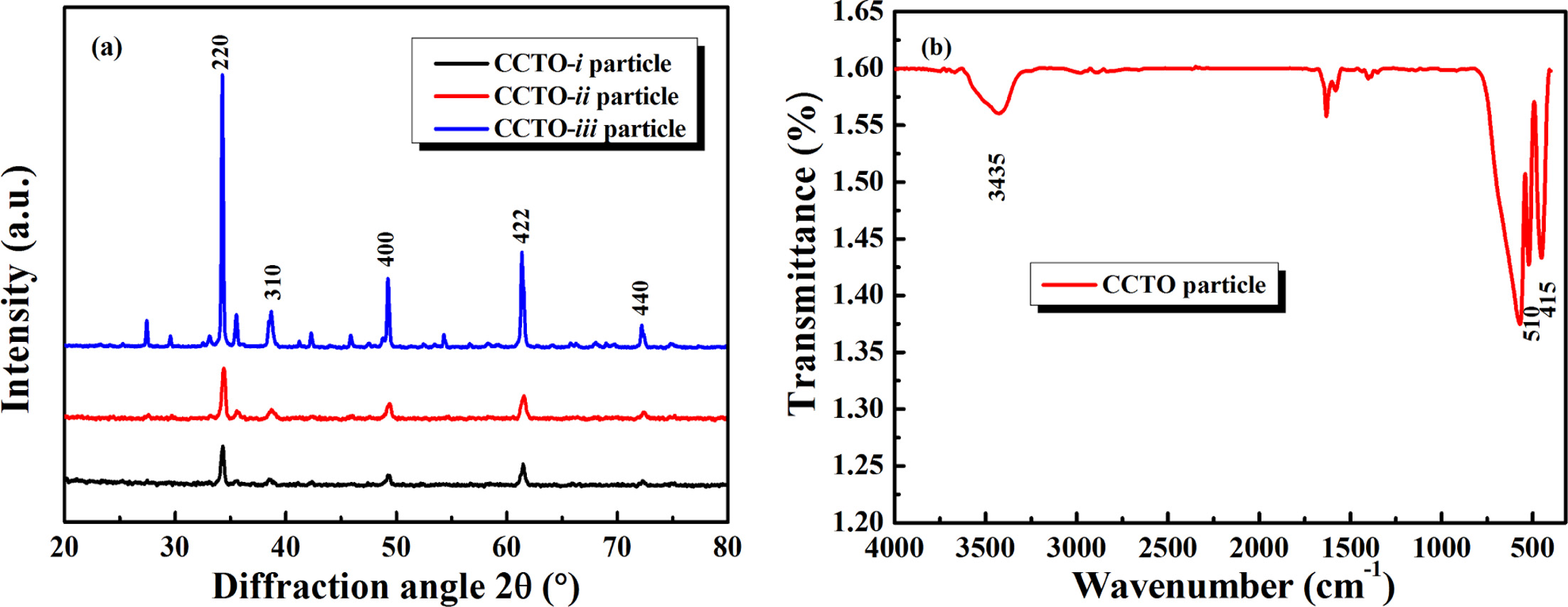
Particle size distribution of CCTO particles (CCTO–i,
CCTO–ii and CCTO–iii) is shown in Fig. 2. The Particle size of
CCTO powders are prepared by sol–gel method and increased as the calcining
temperature rises, and the effective diameter of CCTO particles is a few
hundreds of nanometers. The effective diameter is 310 nm for CCTO–i
particle, which is much lower than the value of 520 nm for CCTO–iii
particle. CCTO–i particle with the lower calcining temperature exhibit
small particle size, which due to lower crystallization temperature. Moreover,
the small powder size of CCTO–i particle exhibit low diffraction
intensity peak, which is consistent with particle size distribution of CCTO–i
particle.
The
structure of CCTO/PF dielectric composites
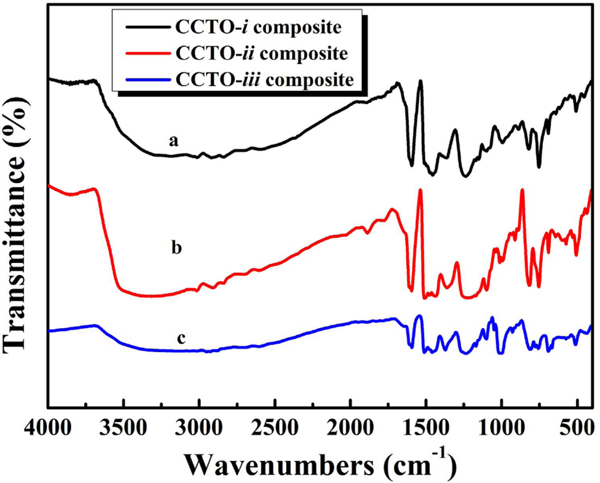
The FTIR spectra of CCTO/PF dielectric composites with 50
vol. % CCTO–i particles, 50 vol. % CCTO–ii particles and 50 vol.
% CCTO–iii particles respectively are shown in Fig. 3. The
characteristic peaks at 1101 cm-1
and 3384 cm-1
are attributed to stretching vibration of C–C and –OH of benzene
ring. A peak appears at 1225 cm-1
which is attributed to the stretching vibration of –CO–. The
characteristic peaks at 458 and 571 cm-1
are attributed to the stretching vibration of Ti–O of CCTO particles in spectra
a, b and c. The characteristic peaks of C–C, –OH, –CO– and Ti–O
become extremely weak in CCTO/PF dielectric composite, which are
owing to the fact that the CCTO particles fill in the PF and change the
original structure of polymer matrix. These characteristic peaks appear in
spectra a, b and c which are an indication that interaction between CCTO and
polymer chain to form the CCTO/PF dielectric composite.
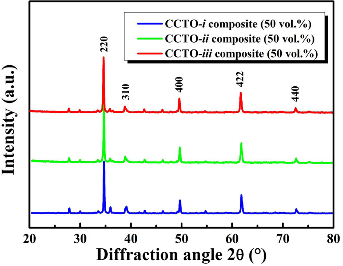
Fig. 4 shows the X–ray diffraction pattern of CCTO/PF
dielectric composites which contain 50 vol. % CCTO–i particles, 50 vol.
% CCTO–ii particles and 50 vol. % CCTO–iii
particles respectively. The XRD analysis for three
types of CCTO/PF dielectric composites shows the predominance of CCTO phase. It
could be seen that all the major diffraction peaks can been indexed as a body
centered cubic perovskite-related structure of space group Im3 according to
JCPDS #75-2188 and diffraction peak of the PF could not be detected, indicating
that CCTO particles dispersed in the PF might have an important effect on the
structure of the molecular aggregation of the PF polymer and destroy the
ordered structure of the polymer matrix.
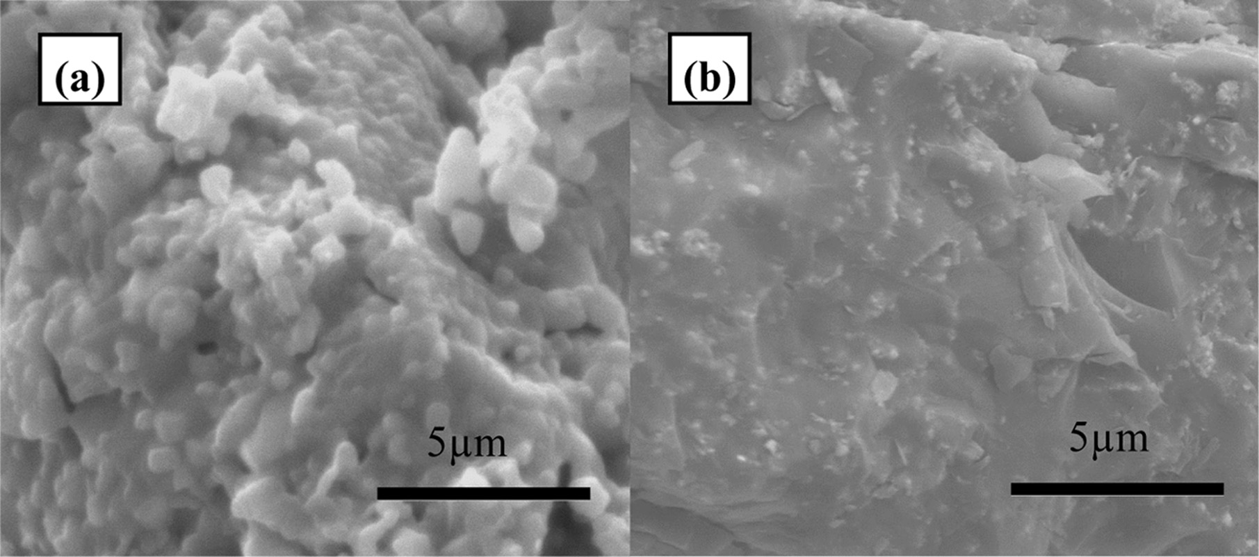
To further make clear the morphology of CCTO powders and
CCTO/PF composite, SEM images of CCTO–i particles and CCTO–i
composites are presented in Fig. 5(a) and (b) respectively.
The result shows that CCTO–i particles are in non-spherical shape and
with an average diameter of 310 nm, which is in accordance with the results of
particle size distribution. Fig. 5(b) shows the surface morphology of CCTO–i
composites. CCTO particles are homogeneously dispersed in PF matrix to form a
composite.
According to the FTIR spectra, X–ray diffraction pattern
and SEM image, it would be indicated that CCTO particles disperse into the PF
to form a ceramic/polymer dielectric composite.
Dielectric
properties of CCTO/PF dielectric composites
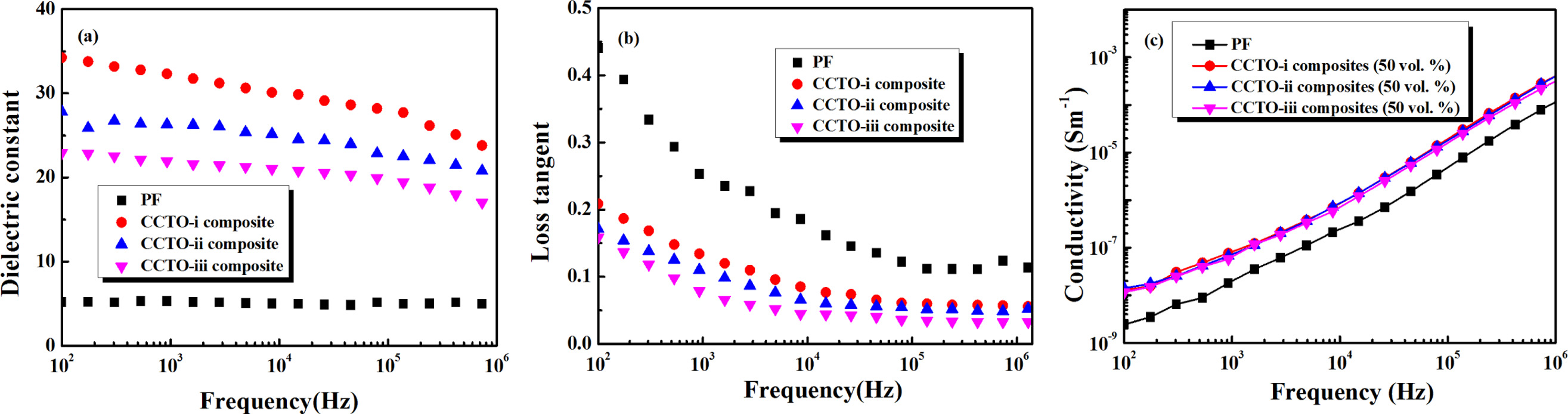
Frequency dependences of dielectric constant of CCTO–i,
CCTO–ii and CCTO–iii composites at room temperature are shown in
Fig. 6(a). It is found that dielectric constant increase gradually with the
particle size of CCTO increase. And in the frequency of 100 Hz to 1 MHz, the
decrease in the dielectric constant with increase in frequency is owing to the
fact that the dipole orientation polarization and interfacial
polarization could not keep up with the alternating field when
the frequency is raised. For the CCTO–i composite with 50 vol. % ceramic
particles, the dielectric constant of this composite is 34.51, which was about
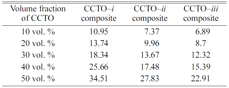
10 times higher than that of pure PF. From the Table 1 it is found that dielectric
constant increased gradually with the increase of
the content of CCTO, and the permittivity of CCTO–i
composite with 50 vol. % ceramic particles reach a maximum value, which is much
higher than those of CCTO–ii composite and CCTO–iii
composite. Moreover, it could be seen that the CCTO/PF
dielectric composites with three types of particle size
are independent in the total range of the measuring frequencies.
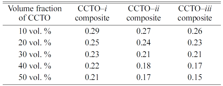
The loss tangent of CCTO/PF dielectric composite measured
in the frequency range from 100 Hz to 1 MHz at room temperature is shown in
Fig. 6(b). With the adding of inorganic filler CCTO, the dielectric loss of
three types of composites could be effectively reduced. For the CCTO–i
composite with 50 vol. % CCTO, the loss tangent decreased to 10-2 which
was lower than that of polymer matrix (10-1).
At the same time, the frequency stability of CCTO/PF dielectric composite is
improved by the addition of CCTO. From the Table 2, it is noticed that when
volume fraction increase, loss tangent of these composites decrease. This drop
of the loss tangent is due to the addition of CCTO to a
certain extent which pins the dipole orientation, thus
reduced the dielectric loss of composite.
Among the three types of ceramic/polymer dielectric
composites, the CCTO–i composite with a smaller particle size exhibit
excellent dielectric properties that could be influence by different particle
sizes. As it could be seen in Fig. 6(c), with the CCTO concentration
is 50 vol. %, the conductivity of CCTO–i composite is only 10-7 S · m-1
at 100 Hz and room temperature and it increase with an increase in the
frequency. It is confirm that insulating layer existed in CCTO/PF dielectric
composite and was consistent with the variation of dielectric permittivity.
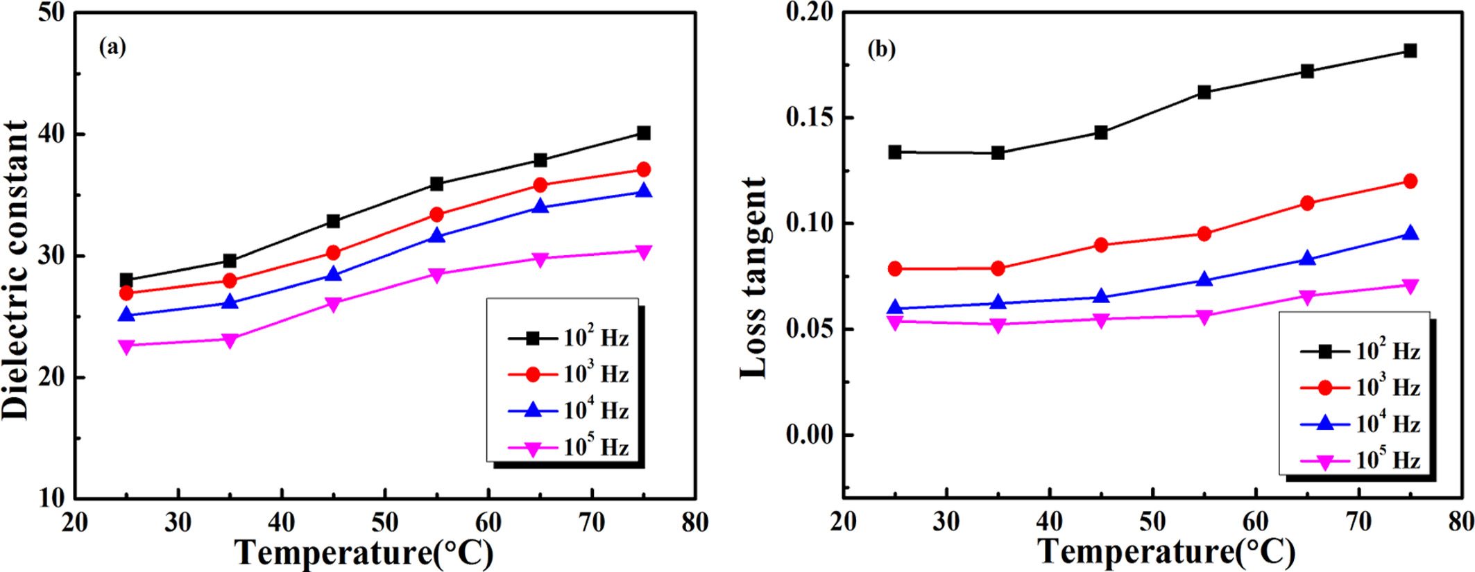
The temperature dependence of dielectric properties is determined for
CCTO/PF dielectric composite. Although the dielectric constant of the CCTO/PF
dielectric composites with three types of
particles was different, all the composites show the same dependence of the dielectric constant and loss on the
temperature. A typical result is shown in Fig. 7, where the temperature dependence of CCTO–i composites with 50
vol. % CCTO particles is measured at various frequencies. As shown in Fig. 7,
the dielectric constant and loss tangent of the CCTO–i composites that
containing 50 vol. % CCTO–i particles increase slightly with
temperature, exhibiting relatively good temperature stability in the measured
temperature range from 25 °C to 75 °C at different measured frequencies.
Temperature stability of dielectric constant is expressed as ΔCT/C25°C
and calculated by the Eq. (1).
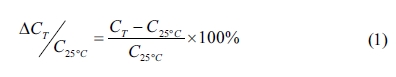
Where ΔCT/C25°C is temperature
stability, C is capacitance. The temperature coefficient of CCTO–i
composite is -3% to 10% from 25 to 75 °C at 100 Hz.
In short, according to the results from the Figs. 6, 7 and
Tables 1, 2, we can make a conclusion that the CCTO–i composite possess
relative high dielectric constant, low loss tangent, as well
as the weak frequency and temperature dependence of
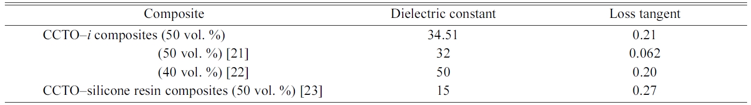
dielectric constant. From the Table 3, comparing with the existing
ceramic/polymer dielectric composites, the dielectric properties of
CCTO–i composite are comparable to these composites.
At the same time, the CCTO–i composite is prepared with the small
particle size of the ceramic, which could make the CCTO/PF dielectric composite
attractive for practical applications.
A
mechanism to interpret the variation of dielectric properties of CCTO–i
composite
In this part, the CCTO–i composite is investigated
on the variation of dielectric properties that is similar to other composites.
Generally, the dielectric properties of CCTO/PF dielectric composite
significantly enhance, which attribute to fill the ceramic particles of CCTO with
giant dielectric properties. For the CCTO, the high dielectric properties are
derived from the specific structure, which is semiconducting
grains with insulating grain boundary. High dielectric
permittivity of ceramic/polymer dielectric composite originates from internal
interfaces effect that may be affected by the variation of interparticle
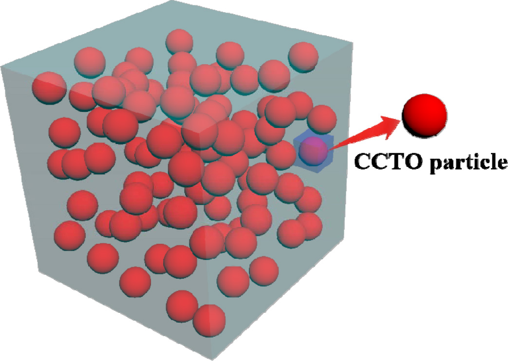
distance and interfacial area [28]. How to calculate the interparticle distance
and interfacial area? The assumption is that the ceramic particle is spherical
and uniformly distribute in the polymer matrix which is
shown in Fig. 8. For another, the interparticle distance of the CCTO/PF
dielectric composites is expressed by the equation (2):
Where d is interparticle distance, r is CCTO
particle radius and v is the volume fraction of CCTO particles. And the
interfacial area of composites could be calculated in certain volume of the 0-3
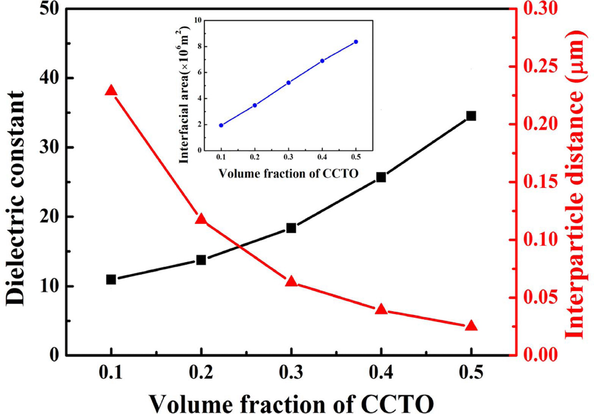
type composite (1 m3). As shown in Fig. 9, with the increase of
volume fraction of CCTO–i particles, interparticle distance decrease
dramatically, and interfacial area, dielectric constant becomes extremely large
at the frequency of 100 Hz and room temperature. With the increase the content
of ceramic powders, the increase of interfacial area of dielectric is
attributed to the reduction of interparticle distance, and then the dielectric
constant increase. The results thus clearly suggest that large interfacial
polarization mechanisms play a very important role in the
dielectric properties of CCTO/PF dielectric composite.
|
Fig. 1 XRD patterns of CCTO particles (a) and FTIR pattern of CCTO particle (b). |
|
Fig. 2 Particle size distribution of CCTO particles. |
|
Fig. 3 FTIR spectra of CCTO/PF dielectric composites. |
|
Fig. 4 XRD patterns of CCTO/PF dielectric composites. |
|
Fig. 5 SEM morphology of the CCTO–i particle (a) and SEM image of surface morphology of CCTO–i composite with 50 vol. % CCTO particle (b). |
|
Fig. 6 Frequency dependence of permittivity (a), loss tangent (b) and conductivity (c) of CCTO/PF dielectric composites with 50 vol. % CCTO particle at room temperature. |
|
Fig. 7 Temperature dependence of dielectric constant (a) and loss tangent (b) of CCTO–i composites with 50 vol. % CCTO particles is measured at various frequencies. |
|
Fig. 8 An illustration of CCTO particle fills in composite. |
|
Fig. 9 Variation of the interparticle distance, interfacial area (inset) and dielectric constant of CCTO–i composites with different volume fraction of CCTO. |
|
Table 1 The dielectric constant of CCTO/PF composites on the different fraction of CCTO at 100 Hz and room temperature. |
|
Table 2 The loss tangent of CCTO/PF composites on the different fraction of CCTO at 100 Hz and room temperature. |
|
Table 3 Dielectric properties of ceramic/polymer composites at 100 Hz and room temperature. |
CCTO/PF dielectric composites with three types of CCTO
particles have been investigated and discussed. For CCTO–i composite
containing smaller particle size of CCTO, the dielectric permittivity reach
about 34.5 with the volume fraction of CCTO–i particle was 0.5 at 100 Hz
and room temperature, while remains a low loss tangent about 0.063. The maximum
of dielectric constant of CCTO–i composite is much larger than that of
polymer matrix (PF) and that of other types of CCTO/PF dielectric composites
with the same volume fraction. The dielectric properties
of CCTO–i composite possess relatively high
permittivity, as well as exhibit good frequency and temperature stability. And
the experimental results show that the large enhancement in dielectric
permittivity may attribute to interface effect. It is believed that CCTO/PF
dielectric composite with high dielectric permittivity and relatively low loss
tangent could be applied in future high-technology fields.
This work was supported by the National Natural Science
Foundation of China (Grant No. 51673157), the Natural Science Basic Research
Plan in Shaanxi Province of China (No. 2017JM5134, No. 2018JM5047
and No.2017JQ2037), Scientific Research Program Funded by Shaanxi Provincial
Education Department (Program No. 15JK2188).
- 1. C. Ehrhardt, C. Fettkenhauer, J Glenneberg, W. Münchgesang, H. S. Leipner, M. Diestelhorst, S. Lemm, H. Beige, and S. G. Ebbinghaus, J. Mater. Chem. A. 2[7] (2014) 2266-2274.
-

- 2. M. N. Feng, X. Huang, H. L Tang, and X. B. Liu, Colloids Surf. A. 441[3] (2014) 556-564.
-
- 3. K. Brandt, V. Salikov, H. Özcoban, P. Staron, A. Schreyer, L.A.S.A. Prado, K. Schulte, S. Heinrich, and G.A. Schneider, Compos. Sci. Technol. 72[1] (2011) 65-71.
-
- 4. P. Thomas, R.S.E. Ravindran, and K.B.R. Varma, J. Therm. Anal. Calorim. 115[2] (2014) 1311-1319.
-
- 5. P. Mishra, P. Kumar, Ceram. Int. 41 (2015) 2727-2734.
-
- 6. P. Mishra and P. Kumar, J. Alloys Compd. 617 (2014) 899-904.
-
- 7. M. Mikolajek, A. Friederich, C. Kohler, M. Rosen, A. Rathjen, K. Krüger, and J.R. Binder, Adv. Eng. Mater. 17 (2015) 1294-1301.
-
- 8. M. Bi, Y. Hao, J. Zhang, M. Lei, and K. Bi, Nanoscale 9 (2017) 16386-16395.
-
- 9. K. Osińska and D. Czekaj, J. Therm. Anal. Calorim. 113 (2013) 69-76.
-
- 10. H. Chen, X. Dong, T. Zeng, Z. Zhou, and H. Yang, Ceram. Int. 33 (2007) 1369-1374.
-
- 11. W. Sun and B. Lu, Mater. Sci. Eng. B 127 (2006) 144-149.
-
- 12. Z.M. Dang, J.K. Yuan, J.W. Zha, T. Zhou, S.T. Li, and G.H. Hu, Prog. Polym. Sci. 57 (2012) 660-723.
-
- 13. Y. Rao and C. P. Wong, J. Appl. Polym. Sci. 92 (2010) 2228-2231.
-
- 14. L.J. Romasanta, P. Leret, L. Casaban, M. Hernández, M.A. de la Rubia, J.F. Fernández, J.M. Kenny, M.A. Lopez-Manchado, and R. Verdejo, J. Mater. Chem. 22 (2012) 24705-24712.
-
- 15. A.P. Ramirez, M.A. Subramanian, M. Gardel, G. Blumberg, D. Li, T. Vogt, and S.M. Shapiro, Solid State Commun. 115 (2000) 217-220.
-
- 16. Y. Wang, X. Wu, C. Feng, and Q. Zeng, Microelectron. Eng. 154 (2016) 17-21.
-
- 17. L. Zhang, X.B. Shan, P.X. Wu, J.L. Song, and Z.Y. Cheng, Ferroelectrics 405 (2010) 92-97.
-
- 18. Y.C. Qing, W.C. Zhou, F. Luo, and D.M. Zhu, J. Mater. Chem. C 1 (2013) 536-541.
-
- 19. X. Yang, W. Huang, and Y. Yu, J. Appl. Polym. Sci. 120 (2011) 1216-1224.
-
- 20. W. Wan, J. R. Luo, C. Huang, J.Yang, Y. B. Feng, W. X. Yuan, Y. J. Ouyang, D. Z. Chen, and T. Qiu, Ceram. Int. 44 (2018) 5086-5092.
-
- 21. F.J. Wang, D.X. Zhou, and Y.X. Hu, Phys. Status Solidi A 206 (2009) 2632-2636.
-
- 22. Z.M. Dang, T. Zhou, S.H. Yao, J.K. Yuan, J.W. Zha, H.T. Song, J.Y. Li, Q. Chen, W.T. Yang, and J.B. Bai, Adv. Mater. 21 (2009) 2077-2082.
-
- 23. S. Babu, K. Singh, and A. Govindan, Appl. Phys. A 107 (2012) 697-700.
-
- 24. A. Srivastava, K. K. Jana, P. Maiti, D. Kumar, and O. Parkash, Mater. Res. Bull. 70 (2014) 735-742.
-
- 25. B.C. Luo, X.H. Wang, Y.P. Wang, and L.T. Li, J. Mater. Chem. A 2 (2014) 510-519.
-
- 26. S. Jesurani, S. Kanagesan, and K. Ashok, J. Sol-Gel Sci. Technol. 64 (2012) 335-341.
-
- 27. C. Yang, H.S. Song, and D.B. Liu, Composites Part B 50 (2013) 180-186.
-
- 28. Y. Yang, B.P. Zhu, Z.H. Lu, Z.Y. Wang, C.L. Fei, D. Yin, R. Xiong, J. Shi, Q.G. Chi, and Q.Q. Lei. Appl. Phys. Lett. 102[4] (2013) 042904.
-
 This Article
-
2020; 21(3): 302-308
Published on Jun 30, 2020
- 10.36410/jcpr.2020.21.3.302
- Received on Oct 15, 2019
- Revised on Jan 18, 2020
- Accepted on Feb 7, 2020
Services
- Abstract
introduction
experimental methods
results and discussions
conclusions
- Acknowledgements
- References
- Full Text PDF
Shared
Correspondence to
- Zongcheng Miao
-
Key Laboratory of Organic Polymer Photoelectric Materials, School of Science, Xijing University, Xi’an, 710123, Shaanxi, People's Republic of China
Tel : +86-29-62307-012
Fax: +86-29-62307-012 - E-mail: zhao1983yang@hotmail.com
Clean-Energy Research Institute(CRI), Hanyang University, 222, Wangsimni-ro, Seongdong-gu, Seoul, 04763, Korea
E-mail: jcpr@hanyang.ac.kr