


- Characterization of metakaolin-based lightweight geopolymers with various foaming agents
Yoorim Rho and Seung-Gu Kang*
Department of Advanced Materials Science and Engineering, Kyonggi University, Suwon 16227, Korea
In this study, lightweight
foamed geopolymers based on metakaolin were synthesized and characterized. By
considering the compressive strength, density, and crystal phase of the
specimens according to the type and amount of forming agent, the possibility of
replacing Al powder, a foaming agent, with Si sludge in lightweight foamed
geopolymers was analyzed. The specimens foamed with Al powder had lower density
than those with Si sludge. However, the compressive strength of the former was
higher than that of the specimens foamed with Si sludge, owing to a more
uniform pore distribution and microstructure. Through this study, lightweight
foamed geopolymers having density of 0.36~1.05 g/cm3 and compressive
strength of 0.7~4.7 MPa can be prepared by controlling the process conditions
such as the amount of Si sludge added, alkali activator concentration, L/S
ratio, etc. The possibility of Si sludge replacing Al powder as a foaming agent
thus has been demonstrated. The lightweight foamed geopolymer fabricated in
this study can be applied to various fields as it can meet the required
physical properties according to the application.
Keywords: Geopolymer, Light Weight, Si Sludge, Metakaolin
Environmental problems caused by greenhouse gases have
occurred in almost all countries around the world since the 2000s. Carbon
dioxide, in particular, is a major greenhouse gas. Research to reduce carbon
dioxide emissions is being actively conducted around the world [1]. Currently,
Portland cement is widely used as a binding material in the construction and
civil engineering field. The cement manufacturing industry meanwhile consumes a
great deal of energy and emits enormous amounts of carbon dioxide gas during
the heat treatment of limestone (CaCO3) and the
combustion of fuel [2, 3]. Specifically, 0.4 to 1.0 tons of carbon
dioxide is discharged to produce one ton of cement, which accounts for 5-7% of
the total carbon dioxide generated by mankind [4, 5]. From this point of view,
geopolymers are attracting attention in the production of binders compared to
Portland cement concrete as greenhouse gas is rarely generated depending on the
weight value of reactive materials of feedstock (SiO2, NaOH, etc.)
[6, 7].
The term “geopolymer” refers to an inorganic polymer
synthesized by the chemical reaction of an alumino-silicate precursor with an
alkali solution [8]. It is generally prepared by reacting raw materials of rich
in Si and Al such as metakaolin with alkali activators such as sodium
hydroxide, potassium hydroxide or water glass [9-11]. Geopolymers consist of
three-dimensional polymer chains. When an alkali solution is brought into
contact with an alumino-silicate oxide as a raw material,
Si and Al ions are dissolved. The dissolved ions are
polymerized into AlO4 and SiO4 tetrahedral precursors
[12, 13]. The basic form of the polymer chain produced
by the polymerization of precursors is -Si-O-Si-O-Si-.
Na+ ions added to the chain as activators and Al3+ ions
are substituted at Si 4 + sites to form a network structure in the
form of -Si-O-Al (Na) -O-Si-. This network
structure finally generates a polymer structure in the form of Mn[-(Si-O2)z-Al-O]n-wH2O
by a complex reaction, where M is an alkali ion such as Na+, K+,
Li+, Ca2+, or Ba2+, Z is 1 to 3, and n is the
degree of polymerization. Because of this polymer structure, industrial waste
such as blast furnace slag and fly ash, which are mostly composed of Si and Al,
are highly applicable as geopolymer materials [14].
Geopolymers have the advantages of excellent mechanical
strength, heat resistance, and chemical resistance
[15]. Microstructure and mechanical properties of
geopolymer highly depends on its composition and curing routes, including type
of alkaline cation and its content, Si/Al ratio, M2O/H2O
ratio, M2O/SiO2 ratio, temperature,
and humidity, among others [16]. Recently, porous
geopolymers with intentional pores have attracted considerable
attention for application to high value-added fields such as thermal
insulation, soundproofing, and fire resistance [16]. On the other hand, the
weight reduction of the construction material has an economic advantage
because it reduces the weight-bearing burden on each
member composing a building. In addition, lightweight materials have low
thermal conductivity, which can be expected to provide thermal insulation [17,
18]. For this reason, research to reduce the weight of geopolymers by
containing a foaming agent in the manufacturing process have been actively
conducted.
In general, there are two common ways to create pores in
geopolymers. The first is to use chemical agents to create bubbles by chemical
reactions during geopolymer curing and to trap the bubbles in the specimen, and
the second is the use of foaming agents, which release the bubbles during
mechanical mixing of the geopolymer slurry [19, 20]. The porosity of the
lightweight geopolymer is highly dependent on the kind and
amount of foaming agent added. It is important to precisely
control the manufacturing conditions in order to prevent bubbles from
collapsing when the generated bubbles are brought into contact with each other
[21].
Al, H2O2, Zn, etc. have been used as
foaming agents. Recently, V. Medri et al. reported that foamed
geopolymers can be prepared through hydrogen gas generation by adding
various types of Si [22-24]. Like Al, a reactive metal powder, Si also reacts
with water and hydroxides in an alkaline environment to produce hydrogen gas
[20]. Reiva et al. reported the pore formation reaction of Si and Al [25].
First, the reaction between Si and alkali activator is shown in Eq. (1).
Si + 2NaOH + H2O → Na2SiO3
+ 2H2↑ (1)
The reactions Al and water or alkali reaction are shown in
Eq. (2), (3), and (4).
2Al + 6H2O → 2Al(OH)3 + 3H2↑ (2)
2Al + 3H2O → Al2O3 + 3H2↑ (3)
2Al + 2OH¯ + 6H2O → 2Al(OH)4¯ + 3H2↑ (4)
Si also has a similar reaction scheme in which gas is
generated by reacting with water or an alkali like Al, a conventional foaming
agent. Therefore, Si could be used as a foaming agent. In this
study, lightweight foamed geopolymers based on metakaolin were
synthesized and characterized. The goal of this study is to replace the
existing foaming agent Al with the waste resource Si sludge in
synthesizing lightweight foamed geopolymers. In
particular, by considering the compressive strength, density, and crystal phase
of the specimens according to the type and amount of forming agent, the
possibility of replacing Al powder with Si sludge was analyzed
Metakaolin was used as a raw material of the geopolymer.
The alkali activator used to activate the geopolymer reaction was sodium
hydroxide (Sodium Hydroxide, Duksan, Extra Pure Grade, 93-100%).
Alkali activators are prepared by mixing distilled water and
sodium hydroxide in a specific molarity. Si sludge used as a foaming agent
originates from the silicon wafer cutting process for semiconductors. The
particle size of Si sludge used was only 106㎛ or less obtained through the
grinding and sieving process. Al powder used as another foaming agent in this
study was 99.9% pure and had a particle size of less than 106㎛ like as Si
sludge.
Metakaolin and alkali activator were mixed in a bowl for
15 min to activate the geopolymer reaction. The mixed slurry was placed in a
5 x 5 x 5cm3 brass mold and
compressed with a hand compact. In the curing process, in order to prevent
cracking caused by rapid evaporation of water, the green body molded in the
mold was put in a zipper bag made of polyethylene together with the mold and
then cured at 70 °C for 24 h. After curing, the specimens were aged at
room temperature for 3 days.
The chemical composition and crystal phase of metakaolin
and the fabricated geopolymer were analyzed using XRF
(X-ray Fluorescence; SPECTRO 2000) and XRD(X-ray
Diffractometer; MiniFlex II, Rigaku, Japan),
respectively. The compressive strength of the produced geopolymer was measured
using a universal testing machine (UTM).
Table 1 shows the chemical composition of metakaolin
indicating that the contents of SiO2 and Al2O3
were 52.1 and 38.5 wt%, respectively. The Si:Al atomic ratio of metakaolin was
calculated as 1.14. Al and Si ions could be eluted when an alkaline activator
solution is contacted with the alumino-silicate materials, and they can be
cured to a dense solid by polycondensation. This process
is called a geopolymeric reaction. The geopolymeric
reaction might generate various polymers such as poly-sialate–siloxo,
poly-sialate–disiloxo, etc. relying upon the ratio of SiO2/Al2O3
in the batch [26].
The ratios of Si/Al of poly-sialates, poly-sialate–siloxo,
and poly-sialate–disiloxo are 1, 2, and 3, respectively. It is
crucial for the geopolymeric reaction to generate an ortho-sialate oligomer
with a Si/Al ratio = 1 because the rate of room temperature
polymerization of oligo-sialates was 100 to 1,000 times faster
than that of ortho-silicate or oligo-siloxo units [27]. Among the geopolymers
based on various industrial wastes, Si/Al = 17.5 was also reported [28].
Therefore, the present raw material, metakolin with a Si/Al
ratio = 1.14, can be considered to
be usable as a raw material of geopolymers.
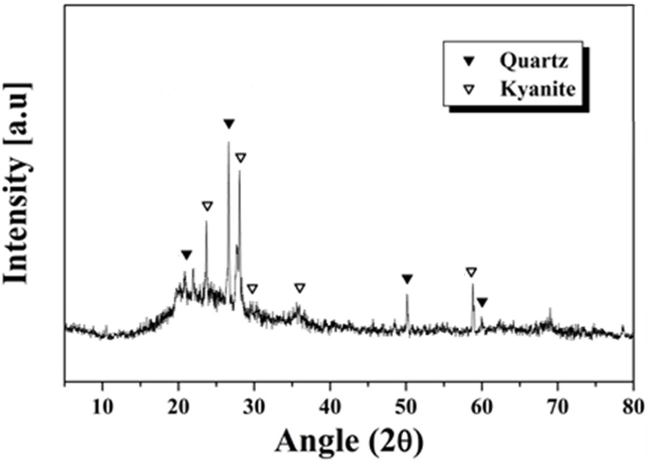
The crystal phase of metakaolin analyzed by XRD is shown
in Fig. 1. There were several phases. First, the large humps, indicating that
there was a significant amount of amorphous phase in the material. It can be
seen also that quartz (SiO2) and kyanite (Al2SiO5)
crystal phases also exist. The cations such as Si and Al could be dissolved out
from metakaolin when the metakaolin is brought into contact
with the alkali solution, owing to the presence of an
amorphous phase. It is, therefore, judged to be suitable as a raw material for
fabricating geopolymer.
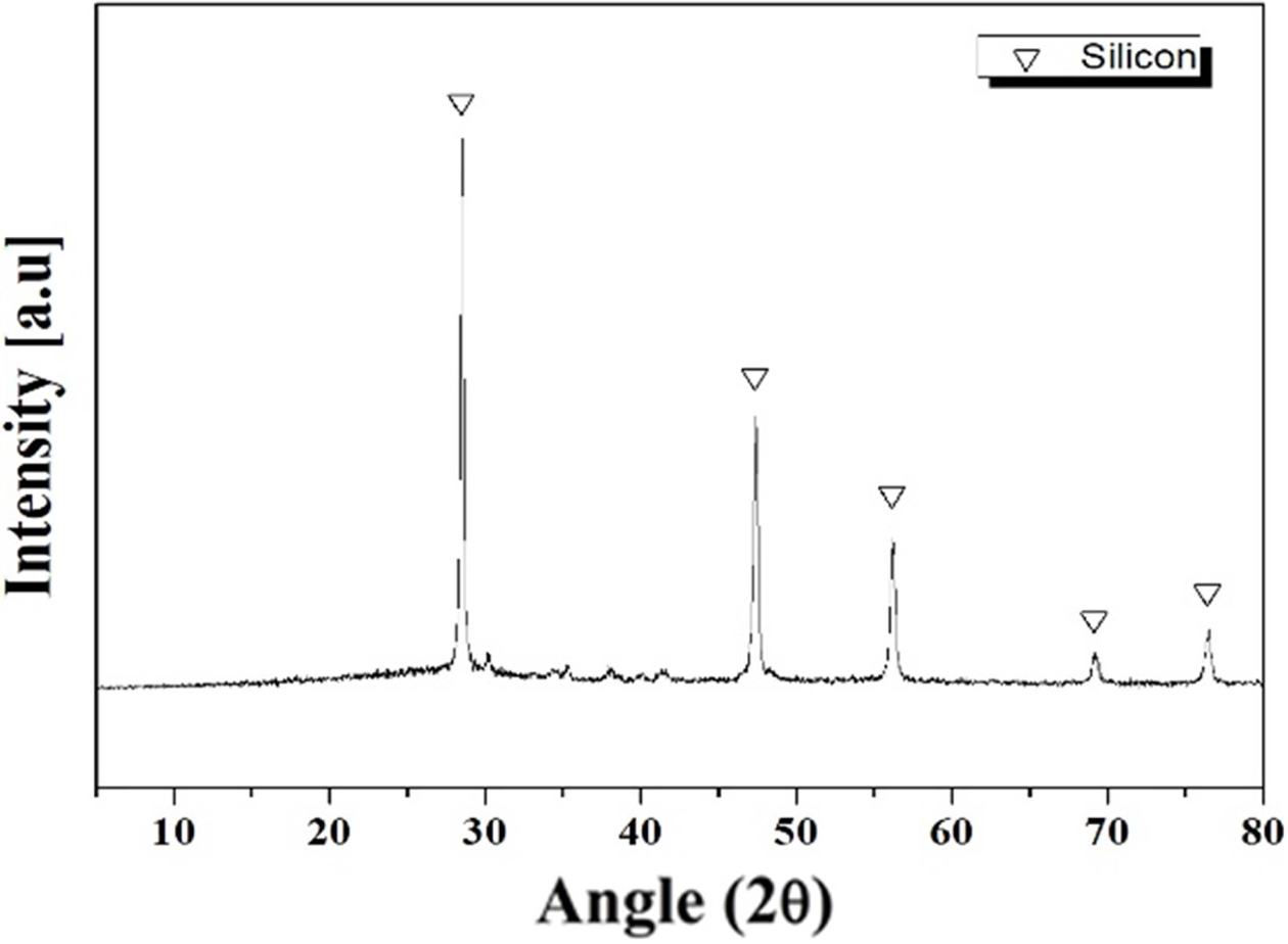
Si sludge is a waste resource emitted during the process
of manufacturing silicon wafers for solar cells and semiconductor modules.
During the process, about 40% of the silicon is produced as sludge-type waste
containing 2% Al2O3, a polishing powder used for
polishing Si wafers. Although the sludge contained 2% Al2O3
phase, the XRD analysis shows only Si crystal peaks, as in Fig. 2.
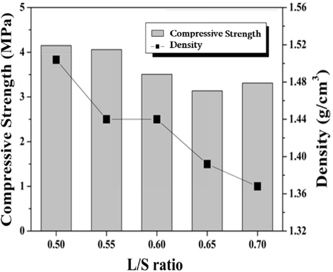
The compressive strength and density of specimens with a
liquid/solid ratio (L/S ratio) ranging from 0.5 to 0.7 were measured and the
results are shown in Fig. 3. No foaming agent was added, and the concentration
of alkali activator solution used was 9 M. The density decreases with the
amount of water because the space occupied by the excess water turned into
pores during the drying process. For example, the density of the specimen made
with L/S values of 0.5 and 0.7 were 1.5 and 1.37 g/cm3,
respectively. As the L/S ratio increased from 0.5 to
0.7, the compressive strength value decreased from 4.2 to
3.4 MPa, respectively, owing to a decrease in density with an increasing L/S
ratio. The specimens shown in Fig. 3 were dense geopolymers without use of a
foaming agent, but the compressive strength values were very low. This is
because the molar concentration of the alkali activator used in the specimen
preparation was too low. As will be mentioned later in Fig. 5,
for the best compressive strength specimens, the concentration of
the alkali activator should be 15 M.
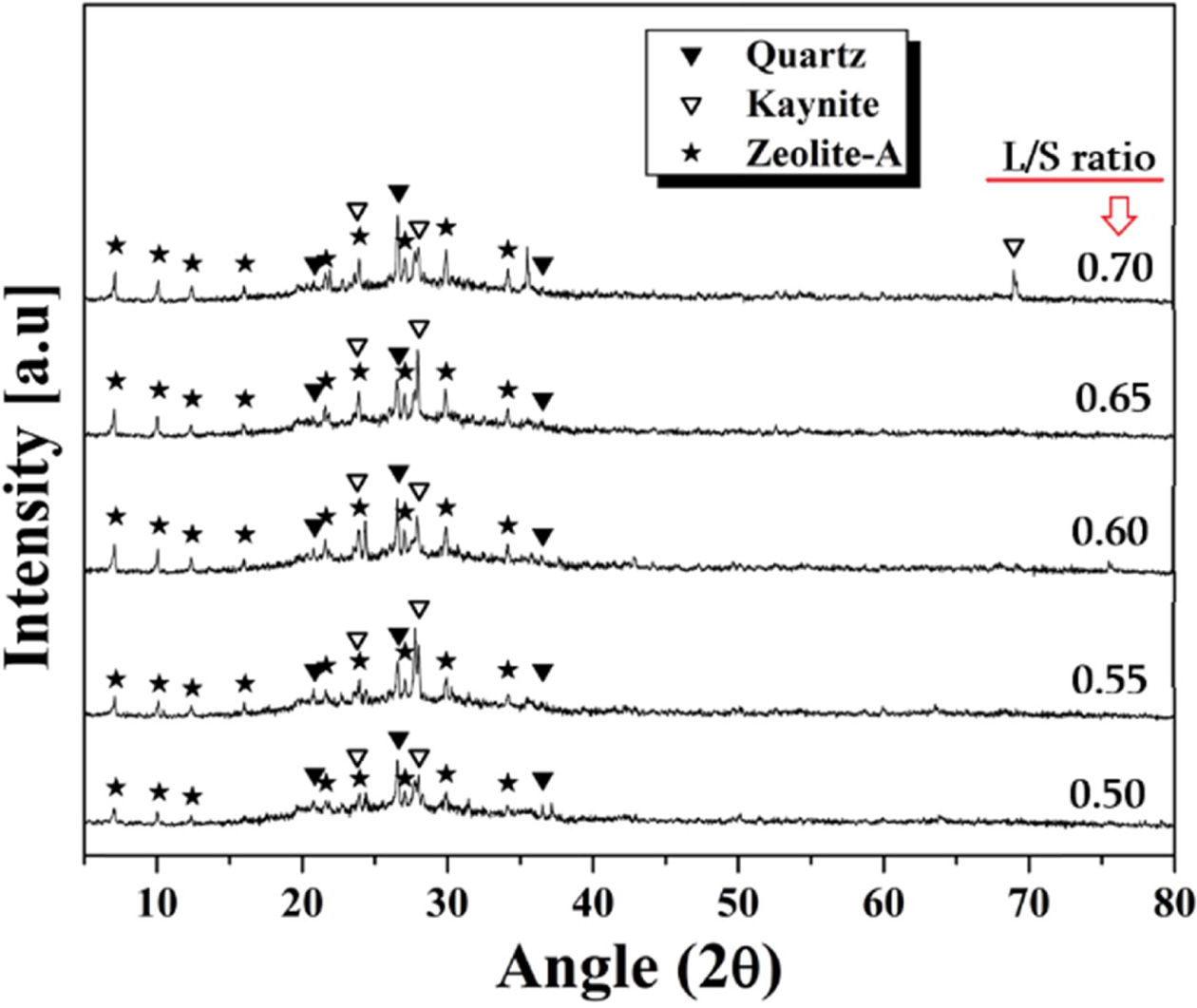
XRD analysis results of the specimens according to the
L/S ratio are shown in Fig. 4. Regardless of the manufacturing conditions,
quartz, kyanite, and zeolite-A crystal phases appeared in all specimens. Quartz
and kyanite originate from the starting material, metakaolin. The
zeolite phase, which is composed of alumino-silicate crystals,
has a chemical formula similar to Mn[-(Si-O2)z-Al-O]n-wH2O,
which is the structure of geopolymers. The existence of zeolite phases in the specimen
is known to be evidence that the geopolymeric reaction occurred. The
zeolite crystals usually can accommodate a wide variety of
cations, such as Na+, K+, Ca2+, Mg2+,
and others, being rather loosely held. The peak intensities of most of the
crystal phases did not change significantly
with the L/S ratio, and meanwhile the zeolite-A crystals showed a slight
increase in peak intensity with the L/S ratio. As the ions move faster in the
liquid phase, the higher the L/S ratio is, the easier the Al and Si ions will
be eluted. As a result, the geopolymer reaction took place vigorously through
the rich liquid phase, resulting in better generation of the zeolite phase.
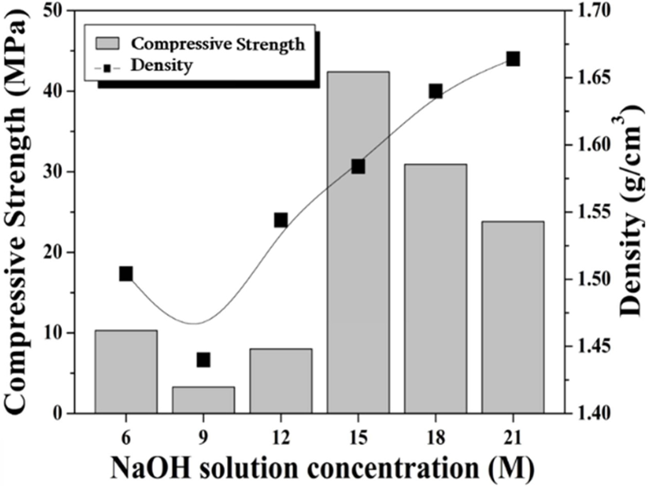
The effect of the alkali activator concentration upon the
compressive strength and density of the specimen prepared with a L/S ratio of
0.6 is shown in Fig. 5. The density of the specimen has a tendency to increase
with increasing activator concentration, except for the
specimen of 9 M NaOH. However, the compressive strength was
highest at 42 MPa when the concentration of the activator used was 15 M.
It is believed that excess alkali interfered with the geopolymer reaction with
an alkali activator of 15 M or more. The increase in the density with the
concentration of the alkaline solution is likely due to the composition of the
liquid phase. The liquid phase used in this study is a mixture of water and NaOH.
The resulting alkaline solution with high molarity is heavier
than pure water. Therefore, the higher the molar concentration of the alkaline solution
is, the higher the unit weight of the solution will be, and thus the density of
the specimen increases.
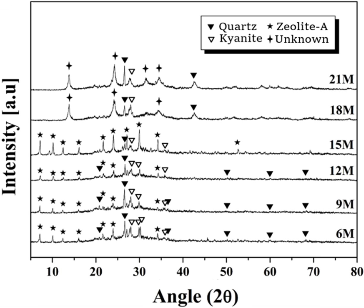
The XRD analysis results of the specimens prepared with
various molar concentrations of alkaline solution are shown in Fig. 6. The L/S
ratio used was 0.6. As mentioned earlier, quartz and kaynite originate from the
starting material, metakaolin, and the new phase generated by the geopolymeric
reaction is zeolite-A crystal. The peak intensity of the zeolite-A crystals
tended to increase with the molarity of the alkaline solution within the range
of 6-15 M, but the zeolite-A phase disappeared and unknown crystal peaks
appeared at a molarity of 18 M or more. As mentioned above, the presence of the
zeolite phase is evidence that a geopolymer reaction has taken place.
Therefore, the use of an alkaline solution with an excessive molar concentration
of 18 moles or more was found to interfere with the
geopolymer reaction.
Analyzing the XRD results in Fig. 5 with the com- pressive strength data in Fig. 6, it can
be seen that the compressive strength values increased with the zeolite
crystal peak intensity. Thus, it can be seen that the excess alkali activator
not only inhibits the geopolymer reaction but also produces an unknown
crystalline phase (possibly a Na-based crystalline phase). The
resulting unknown crystalline phase lowered the compressive strength
value of the specimen. Therefore, for preparing the
geopolymer in the present study, the optimum value of the alkaline solution
concentration was determined to be 15 M. However, it is thought that the
discussion of the exact relationship between the mechanical strength value and
the type of crystal phases formed identified by XRD results may be possible
when the additional experiments is performed.
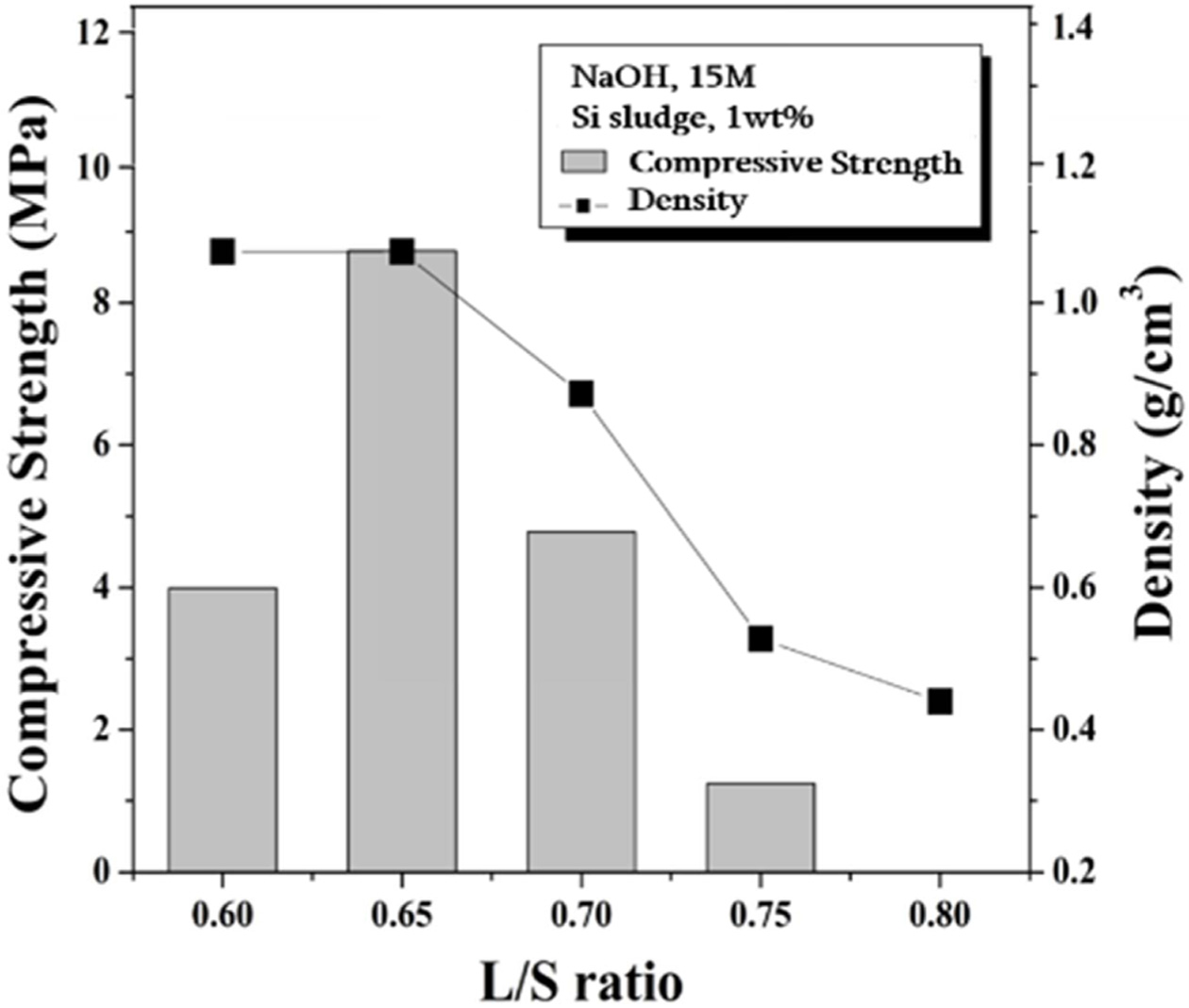
The compressive strength and density of foamed geopolymers
containing 1 wt% Si sludge and 15 M NaOH as a function of the L/S ratio
are shown in Fig. 7. The density decreased with the L/S ratio. Overall, a lightweight
specimen with a density of 0.35 to 1.1 g/cm3 was produced. As shown in Eq. (1), the Si sludge
generates hydrogen gas upon contact with water. The generated hydrogen gas is
trapped inside the geopolymer and expands to make the geopolymer into a porous
structure. As the amount of water in the geopolymer increases, the Si sludge
generates more bubbles, which ultimately reduces the density of the specimen.
The compressive strength of the specimens was 1.2-8.7 MPa in a L/S ratio
ranging from 0.6 to 0.8, with a maximum compressive strength at a L/S ratio of
0.65. When the L/S ratio is 0.6, the dissolution rate of the Si and Al ions is not high enough, and consequently the geopolymer reaction is suppressed
and the strength is considered to be low. The compressive strength of the
specimen decreased with the L/S ratio in a L/S ratio range of 0.7-0.8. The reason for this is that more
porous structures were produced as
the amount of water increased. In particular, the strength of specimen made
with an L/S ratio of 0.8 was too low to be measured by UTM.
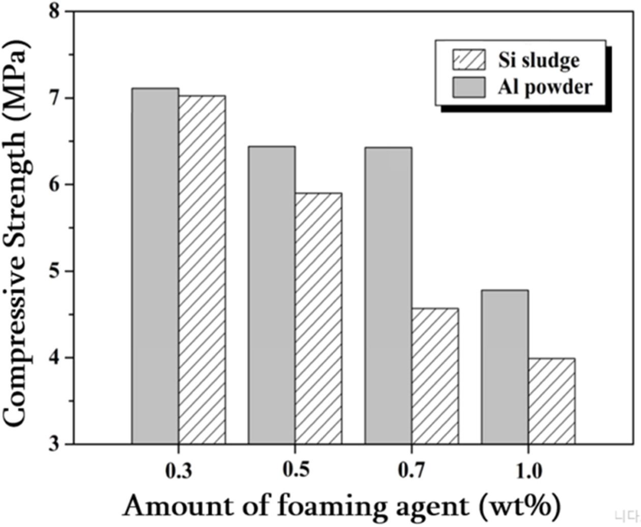
The density and compressive strength of lightweight foamed
geopolymer specimens prepared using two kinds of foaming agents, Al powder and
Si sludge, are shown in Figs. 8 and 9, respectively. The concentration of
alkali activator used when preparing the specimen was 15 M and
the L/S ratio was set at 0.65. The specimens foamed with Si
sludge had decreased density from 1.33 to 1.06 as the amount of Si
sludge added was increased within a range of 0.3-1.0 wt%. The specimens foamed
with Al powder had a lower density overall than the Si foamed specimens, and
the density change with the amount of Al powder added was not significant.
Regardless of the type of foaming agent, the compressive strength decreased as
the amount of foaming agent added increased. Overall, the compressive
strength of the Al powder-added specimens was higher than that of
the Si sludge-added specimens. In particular, in the case
of 0.7 wt% foaming agent added, the Al powder-added specimen showed 20.5%
higher com- pressive
strength than the Si sludge-added specimen. This is thought to be due to the
more uniform pore distribution and microstructure of the specimens made with Al
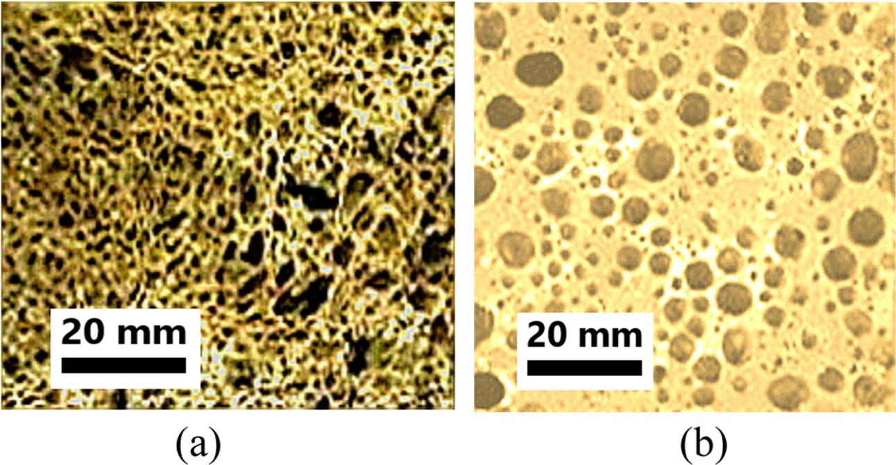
powder than those made with Si sludge, as shown in Fig. 10.
Fig. 10 shows photographs of specimens foamed with Al
powder (a) and Si sludge (b). The samples made of Al powder had larger pores
than those of the samples made of Si sludge. For this reason, the density of
specimens made of Al powder was lower than that of Si sludge. However, it can
be seen that the pore size distribution and microstructure of the
specimens prepared by Al powder are more uniform than
that of the specimens prepared by Si sludge. A non-uniform pore size
distribution and microstructure causes the specimen to degrade in terms of
compressive strength.
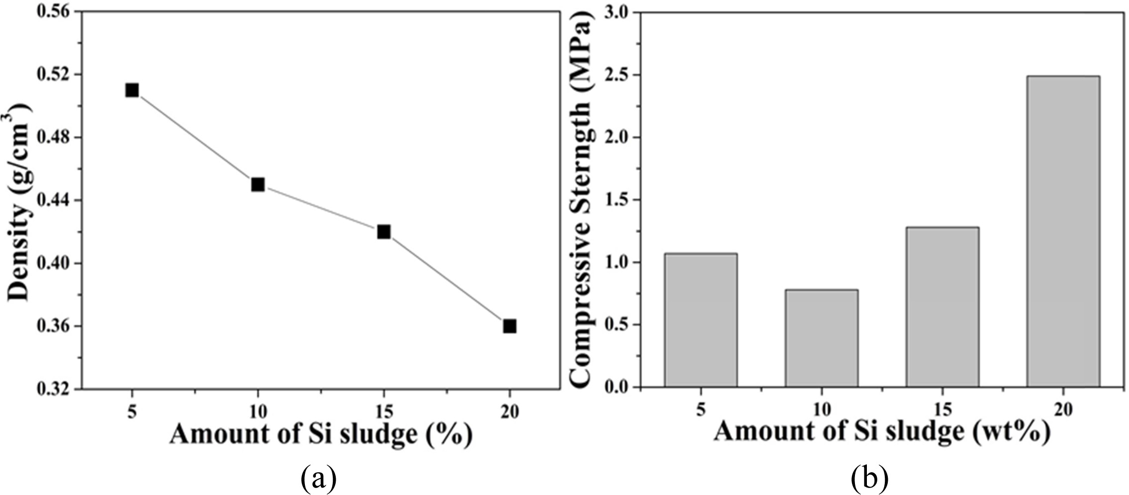
In order to investigate the effect of the large amount of
Si sludge addition on the weight reduction of the geopolymer, the density and
compressive strength of the specimens prepared with 5 to 20 wt% Si sludge were
measured and the results are shown in Fig. 11. The density of geopolymers
decreased with the amount of Si sludge added. For example, the densities of the
specimen made with 5 and 20 wt% of Si sludge addition were 0.51 and 0.36,
respectively. On the other hand, the compressive strength made with 5 wt% Si
sludge added was 1.1 MPa, but decreased to 0.8 MPa for the specimen with 10 wt%
Si sludge. However, when the added amount was more than 15%, the compressive
strength increased conversely with the Si sludge. For example, the compressive
strength of the specimen made with 20 wt% Si sludge was 2.5 MPa. The
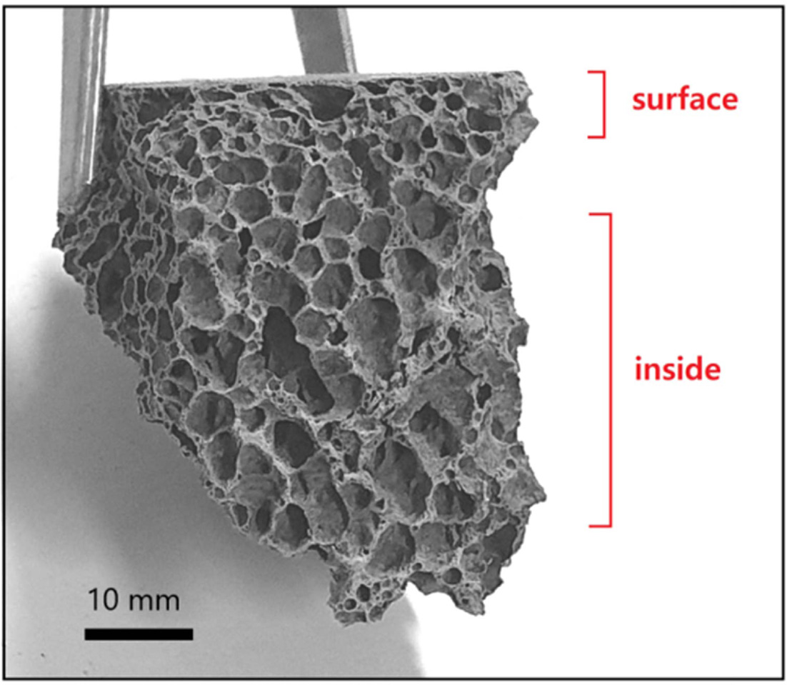
reason why the compressive strength of the specimen made with the
foaming agent 15% or more is increased is that bubbles generated on the surface
escape easily from the specimen before the specimen is hardened. As a result,
the surface was denser than the interior. Of course, there are still many pores
inside the specimen, and thus the density decreases with the amount of blowing
agent. Due to densification of the surface, it is thought that the compressive
strength increased again in the specimen with more than 15 wt% of Si sludge.
This phenomenon can be seen in Fig. 12. The pores near the surface of the
specimen are small, while the pores in the inner part are large.
As a result, it was possible to manufacture metakaolin-based
lightweight foamed geopolymers having compressive strength of
0.7-2.4 MPa and density of 0.51-0.36 by using 5-20 wt% of Si sludge instead of
Al powder as a foaming agent in this study.
|
Fig. 1 XRD pattern of metakaolin used as starting material for fabricating geopolymers. |
|
Fig. 2 XRD pattern of Si sludge used as forming agent. |
|
Fig. 3 Compressive strength and density of geopolymers made with various L/S ratios. Alkali activator concentration used was 9 M and no foaming agent was added. |
|
Fig. 4 XRD pattern of geopolymers made with various L/S ratios. Alkali activator concentration used was 9 M and no foaming agent was added. |
|
Fig. 5 Compressive strength and density of geopolymers made with various alkali solution concentrations. L/S ratio used was 0.6. |
|
Fig. 6 XRD pattern of geopolymers made with various alkali solution concentrations. L/S ratio used was 0.6. |
|
Fig. 7 Compressive strength and density of light weight geopolymers made with various L/S ratios. Alkali activator concentration used was 15 M, and amount of Si sludge added was 1.0 wt%. |

|
Fig. 8 Graph of density changes of light-weight geopolymers made of Si sludge and Al Powder. Alkali activator concentration used was 15 M, and the L/S ratio used was 0.65. |
|
Fig. 9 Compressive strength of light-weight geopolymers made of Si sludge and Al Powder. Alkali activator concentration used was 15 M, and the L/S ratio used was 0.65. |
|
Fig. 10 Optical photograph of light-weight geopolymers made of 0.5 wt% (a) Si sludge and (b) Al Powder. Alkali activator concentration was used 15 M, and the L/S ratio used was 0.65. |
|
Fig. 11 Physical properties of light-weight geopolymers made with various amounts of Si sludge; (a) density, and (b) compressive strength. Alkali activator concentration used was 15 M, and the L/S ratio used was 0.65. |
|
Fig. 12 Picture of fractured surface for foamed geopolymer made with 15 wt% Si sludge. |

In this study, experiments were carried out for the
purpose of replacing Al powder, which is used mainly in manufacturing
lightweight foamed geopolymer, with Si sludge produced as industrial waste, and
we have drawn the following conclusions.
1) The presence of zeolite crystalline phases generated
in metakaolin geopolymer specimens indicates that a geopolymeric reaction
occurred in the specimen.
2) As a higher L/S ratio is employed, the zeolite phase is
well formed due to the active geopolymer reaction caused by easy dissolution of
Al and Si ions. Considering formability and reactivity, an L/S ratio of 0.6 ~
0.65 is suitable for the production of metakaolin-based geopolymers.
3) Increasing the molarity of the alkali activator
increased the zeolite crystal peak in XRD analysis, but above 15 M, the excess
alkali inhibited the geopolymer reaction and the zeolite crystal phase
generation.
4) Partial densification was observed near the surface of
the specimen made with more than 15 wt% of Si sludge, resulting in an increase
in compressive strength.
5) By adding Si sludge in the place of Al powder, which is
a conventional foaming agent, it was possible to manufacture lightweight foamed
geopolymer based on metakaolin. By controlling the process conditions such as
the concentration of alkali activator, L/S ratio, and the amount of Si sludge
added, specimens with a density of 0.36 to 1.05 g/cm3 and
compressive strength of 0.7 to 4.7 MPa could be prepared.
This work was supported by Kyonggi University Research
Grant 2018.
- 1. Y. S. Kim and S. G. Kang, J. Korean Cryst. Growth Cryst. Technol. 24[1] (2014) 15-20.
-

- 2. J. J. Bang and S. G. Kang, J. Korean Cryst. Growth Cryst. Technol. 28[5] (2018) 199-205.
-
- 3. D.M.A. Huiskes, A. Keulen, Q.L. Yu, and H. J. H. Brouwers, Materials and Design, 89 (2016) 516-526.
-
- 4. E. Mohseni, M. J. Kazemi, K. Mahdi, B. Zehtab, and B. Abak, Constr. Build. Mater. 209 (2019) 532-540.
-
- 5. S. Top, H. Vapur, M. Altiner, D. Kaya, and A. Ekicibil, J. Mol. Struct. 1202 (2020) 127-136.
-
- 6. S. Mesgari, A. Akbarnezhad, and J. Z. Xiao, Constr. Build. Mater. 236 (2020) 117571.
-
- 7. B. C. McLellan, R. P. Williams, J. Lay, A. R. van, and G. D. Cordor, J. Cleaner Prod. 19 (2011) 1080-1090.
-
- 8. M. N. Rui, R. C. Pullar, and A. L. João, Prog. Mater. Sci.
-
- 9. T. A. Nour and H. A. Elsayed, HBRC Journal, 14 (2018) 159-164.
-
- 10. C. Yi, H. Ma, H. Chen, J. Wang, Shi Jing, Z. Li, and M. Yu, Const. Build. Mater. 187 (2018) 318-326.
-
- 11. Z. Peng, Y. Zheng, K. Wang, and J. Zhan, Compo. B Eng. 152 (2018) 79-95.
-
- 12. C. Shi, A. F. Jiménez, and A. Palom, Ceme. Concr. Res. 41 (2011) 750-763.
-
- 13. J. Davidovits, Alkakine Cements and Concretes, (1994) 131-149.
- 14. J. Davidovits, J. Therm. Anal 37 (1991), 1633-1656.
-
- 15. S. Quentin, Institut Géopolymère 4 (2015).
-
- 16. P. He, M. Wang, S. Fu, D. Jia, S.Yan, J. Yuan, J. Xu, P. Wang, and Y. Zhou, Ceram. Int, 42 (2016) 14416-14422.
-
- 17. W. Rickard, L. Vickers, and A. V. Riessen, App. Clay Sci, 73 (2013) 71-77.
-
- 18. W. Rickard, L. Vickers, and A. V. Riessen, App. Clay Sci. 73 (2012) 71.
-
- 19. K. B. Han, Kor. Const. Safety Association 33 (2005) 34.
-
- 20. F. Xu, G. Gu, W. Zhang, H. Wang, X. Huang, and J. Zhu, Cer. Int. 44 (2018) 19989-19997.
-
- 21. R. A. Aguilar, O. B. Díaz, and J. I. E. García, Const. Build. Mater. 24 (2010) 1166-1175.
-
- 22. S. J. Lee, E. M. An, and Y. H. Cho, J. Rec. Const. Resources. 4[4] (2016) 363-370.
-
- 23. Z. Zhang, J. L. Provis, A. Reid, and H. Wang, Const. Bldg. Mat. 56 (2014) 113.
-
- 24. V. Medri and A. Ruffini, Cer. Int. 38 (2012) 3351.
-
- 25. V. Medri, E. Papa, J. Dedecek, H. Jirglova, P. Benito, A. Vaccari, and E. Landi, Cer. Int. 39 (2013) 7657.
-
- 26. C. Leiva, Y. L. Galiano, C. Arenas, B. A. Fariñas, and C. F. Pereira, Waste Manag. 95 (2019) 504-512.
-
- 27. K. Pimraksaa, P. Chindaprasirt, A. Rungchet, K. Sagoe-Crentsil, and T. Sato, Mater. Sci. and Eng. A 528 (2011) 6616-6623.
-
- 28. M. North and T. Swaddle, Inorg. Chem. 39 (2000) 2661-2665.
-
- 29. S. Songpiriyakij, T. Kubprasit, C. Jaturapitakkul, and P. Chindaprasirt, Constr. Build. Mater. 24 (2010) 236-240.
-
 This Article
-
2020; 21(S1): 74-80
Published on May 31, 2020
- 10.36410/jcpr.2020.21.S1.s74
- Received on Dec 30, 2019
- Revised on Apr 13, 2020
- Accepted on May 4, 2020
Services
- Abstract
introduction
experimental
results and discussion
conclusion
- Acknowledgements
- References
- Full Text PDF
Shared
Correspondence to
- Seung-Gu Kang
-
Department of Advanced Materials Science and Engineering, Kyonggi University, Suwon 16227, Korea
Tel : +82-10-5265-2681 - E-mail: sgkang@kgu.ac.kr
Clean-Energy Research Institute(CRI), Hanyang University, 222, Wangsimni-ro, Seongdong-gu, Seoul, 04763, Korea
E-mail: jcpr@hanyang.ac.kr