


- Influence of substrate surface-grinding on surface roughness of zirconia coatings fabricated by room temperature spray processing
Jeong Jun Kim and Jong Kook Lee*
Department of Advanced Materials and Engineering, Chosun University, Gwangju 61452, Korea
Zirconia ceramics used for
dental implants have low bioactivity. Their surface roughness needs to be
enhanced for improved bone-bonding ability and cell adhesion. Zirconia implants
in the gums with low surface roughness have a probability detachment over time.
In this study, a zirconia substrate zirconia was coated by a powder via spray
processing at room temperature (25 oC) to increase its surface
roughness. In addition, we investigated the morphology of the as-produced rough
substrate, including microstructural evolution. Four types of zirconia
substrates with different surface texture were fabricated via surface-grinding
by silicon carbide (SiC) abrasive papers (#220, #400, #800) after sintering.
Room temperature spray processing was carried out using a commercial zirconia
powder after thermal treatment. The as-produced zirconia coatings showed dense
microstructure and uniform thickness. Surface roughness of zirconia substrate
was greatly enhanced depending on the surface texture of the substrate. Surface
texture by substrate grinding affected coating morphology; however, it did not
increase the surface roughness of the substrate or the coatings. High-roughened
coatings and thick coating layer could be obtained from the as-sintered
substrate owing to its high surface roughness.
Keywords: Zirconia substrate, Room temperature spray processing, Surface roughness
3 mol% yttria-stabilized tetragonal zirconia polycrystals
(3Y-TZP) exhibits superior mechanical properties such as high
fracture toughness (~10 MPa·m-1),
high flexural strength (~1,300 MPa), elastic
modulus (~210 GPa), and abrasion
resistance (~1,200 Hv) [1-4]. It also characterized
by biological and optical properties, for example, good biocompatible
properties, i.e., corrosion resistance, non-toxicity,
minimal ion release, low affinity to bacterial colonization,
and good esthetics [5, 6]. The mechanical, biological
and optical properties of zirconia dental implants are related to the ionic and
phase composition, hydrophilicity, and surface roughness, which depend on the
bulk composition as well as the surface treatment of the implants [7, 8]. Even
though 3 mol% yttria-stabilized tetragonal zirconia (3Y-TZP) is the most
commonly used material, yttria content of zirconia bulk materials can vary from
3 to 5 mol% [9, 10].
Most of zirconia implants are fabricated by the milling
of ceramic block using a computer‐aided design and computer‐aided manufacturing
(CAD/CAM) system, after post-sintering [11]. Shaping of zirconia blocks by cutting
or grinding creates several invisible microcracks on the
machined implant surface that might induce microstructural
disintegration or failure after implantation, limiting the
use of this material as a dental implant [12, 13]. Fabrication of zirconia
implants by CAD/CAM and sintering usually results in a relatively smooth
surface, that reduces its bone-bonding ability and cell adhesion [14, 15].
The surface treatment of zirconia dental implants is
diverse and has not been thoroughly studied. Several efforts have been made to
roughen the zirconia implant surface to improve its
osseointegration. Numerous surface modifications are currently
being applied, such as sandblasting and acid etching to enhance the surface
roughness of CAD/CAM machined zirconia implants [16, 17]. Zirconia particles
are also used as an effective coating material, and surface coating is a
frequently used method to improve the surface roughness and bone-bonding
ability of dental zirconia implants [18, 19].
In this study, we applied a zirconia coating on zirconia
substrate to obtain a highly roughened zirconia surface by spray processing at
room temperature (25 oC), to improve the bone-bonding ability
and osseointegration of the implant. We also investigated
the effect of substrate texturing and
roughness on coating morphology, including microstructural
evolution, surface roughness, and coating thickness.
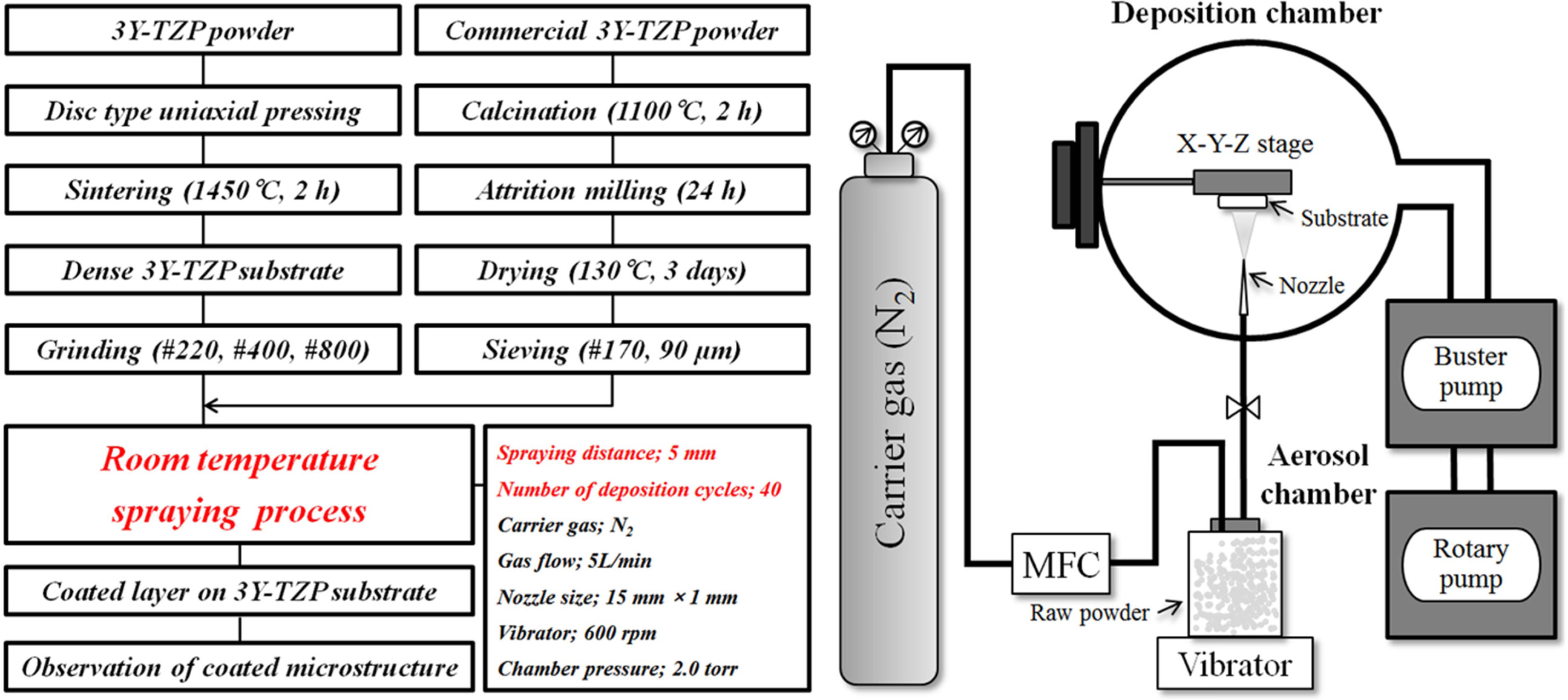
Materials
Commercial 3Y-TZP powder was used as the raw material to
fabricate the zirconia coating and substrate. To match the
processing condition for room temperature spray
processing, 3Y-TZP powder was heat-treated at 1,100 oC for 2 h
to enlarge the particle size and weight. After calcination, attrition-milling
was performed for 24 h. After drying, the powder was sieved to prevent the
nozzle from clogging during coating.
Dense zirconia substrate 1 cm in diameter was fabricated
by uniaxial pressing and sintering at 1,450 oC for 2 h. Surface
microstructure and roughness of substrate were investigated via field emission
scanning electron microscopy (FE-SEM) and atomic force microscopy (AFM). To
change the surface texture of the zirconia substrate, abrasive milling was
performed using the three types of silicon carbide (SiC) paper (#220, #400,
#800).
Coating
The 3Y-TZP substrate was coated with zirconia particles
by spray processing at room temperature. A few preliminary experiments were
performed to determine the optimum
coating parameters as described in our previous study [20].
Pressure difference between aerosol and deposition chambers was maintained at 1
atm under the nitrogen gas flow rate of 5 L/min. The distance
between the nozzle and the substrate, termed as spraying
distance, was set at 5 mm. Aerosol of 3Y-TZP particles in the deposition
chamber was formed by the injection of nitrogen gas and severe vibrations at
approximately 600 rpm. The 3Y-TZP particles carried via nitrogen
flow into the deposition chamber were rapidly impacted onto
the substrate and deposited as the coating layer. To obtain a
thick coating on the substrate, coating cycle was repeated
a maximum of 40 times in succession, using a slit nozzle with a size of
15 × 1 mm2. Detailed experimental procedure for the
preparation of substrate and room temperature spray processing is indicated in
Fig. 1.
Characterization
The change in the color of the coating with deposition
cycle was observed using optical microscope, and its phase composition was
analyzed by X-ray diffraction (XRD). The morphology and
microstructure of the coated layer were investigated both on planar and
perpendicular surfaces using an FE-SEM. Coating thickness was
measured as a function of the deposition cycle and the values were compared
based on the degree of surface-grinding. Surface morphology and microstructure
of the 3Y-TZP coating were observed by SEM and AFM and investigated with
respect to the deposition cycle and surface-grinding type. From the AFM image,
the roughness parameter (Ra; centerline average roughness) was measured, and
the relation between coating properties and processing parameters was analyzed.
|
Fig. 1 Schematic for the preparation of 3Y-TZP coating powder and substrate, and the room temperature spray processing. |
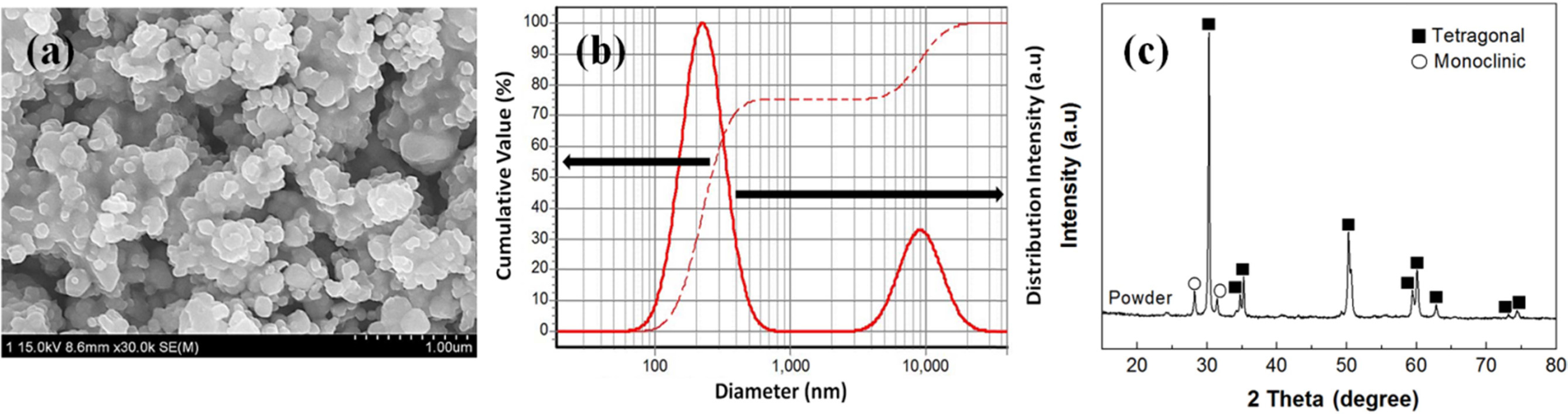
Heat treatment of the 3Y-TZP powder at high temperature is
essential to obtain the powder that is suitable for spray coating at room
temperature; it also provides sufficient impaction energy to the particles for collision
[21, 22]. All 3Y-TZP particles after calcination showed an
equiaxed shape with uniform agglomeration as shown in Fig. 2(a). From the
analysis of particle size distribution (Fig. 2(b)), calcined 3Y-TZP powder had
primary and secondary agglomerate sizes of 287 nm and 3.3 µm, respectively, and
composed of 75 vol% primary and 25 vol% secondary agglomerates. Calcined
and milled 3Y-TZP powder was characterized as the main tetragonal phase with a
trace of monoclinic phase as per the XRD analysis (Fig. 2(c)), indicating
partial phase transformation by heat-treatment and attrition milling.
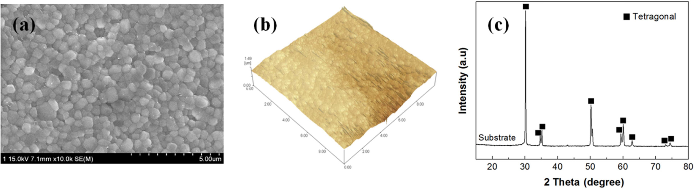
Surface microstructure and morphology of the as-sintered
3Y-TZP substrate observed by SEM and AFM are shown in Fig. 3, indicating that
the specimen has homogeneous microstructure composed of all
tetragonal grains of 500 nm, and 0.28 µm surface roughness (Ra)
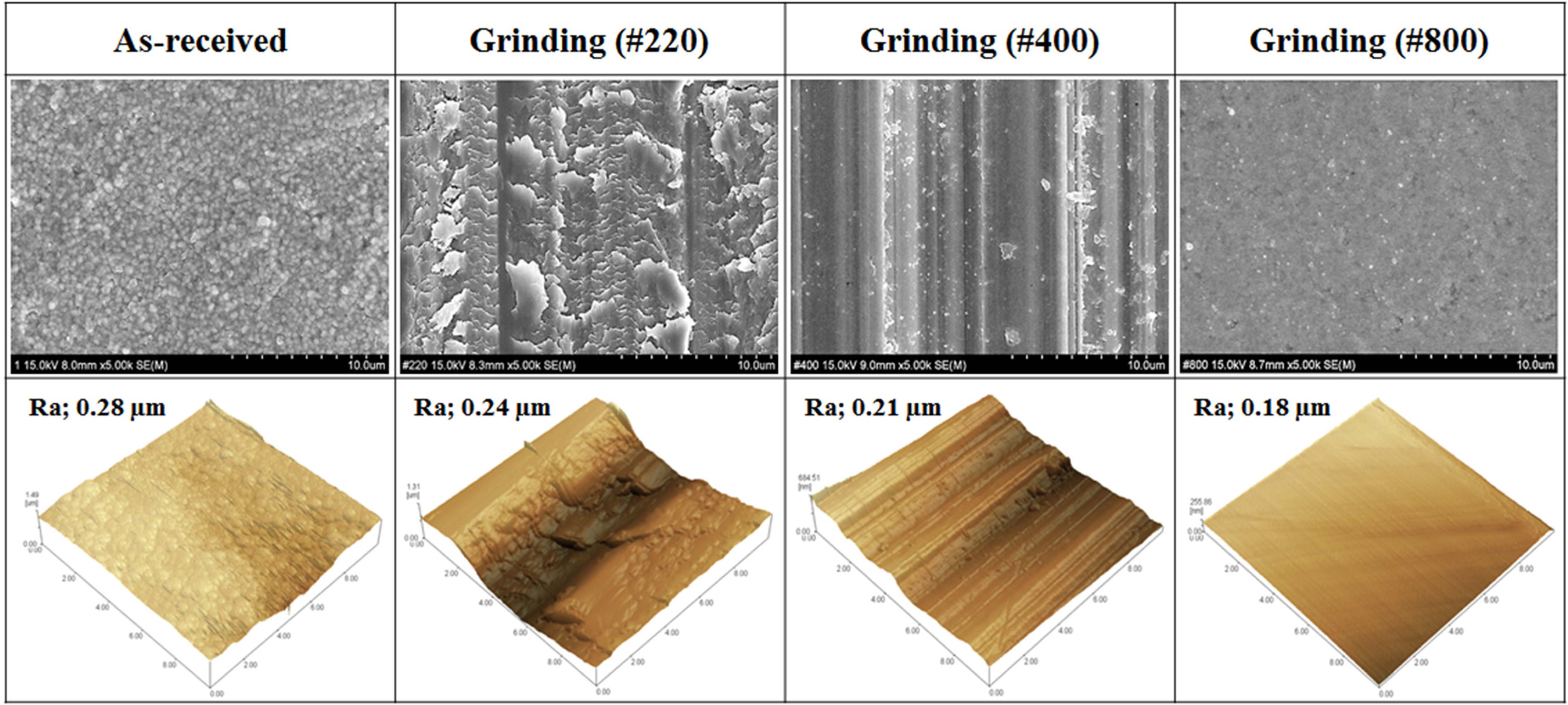
measured from AFM image. Fig. 4 shows the surface morphology and roughness of
the 3Y-TZP substrate after surface-grinding by three types of SiC abrasive.
Several scratches in vertical direction were observed from the SEM
photographs, but the scale and frequency of scratches
were dependent on the type of the SiC abrasive. Surface-grinding by
coarse SiC abrasive (#220) induced large scale scratches on
the substrate surface with relatively low frequency. In contrast,
surface-grinding by fine SiC abrasive (#800) greatly reduced the scratch mode
on the substrate surface, resulting in low surface
roughness (Ra). Even though large scratches were
formed on the substrate surface by surface-grinding it caused a
decrease in the roughness value (Ra) from 0.28 µm (as-sintered substrate) to
0.18 µm (#800 SiC abrasive).
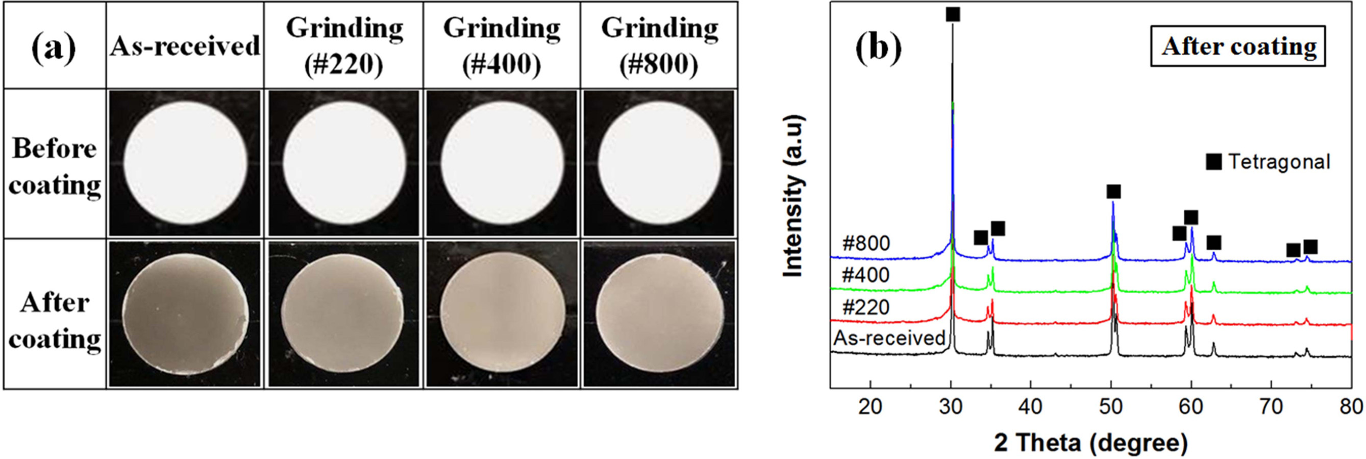
Surface color of the as-sintered 3Y-TZP substrate
corresponds to that of the ivory, which is the typical color of 3Y-TZP. After
the coating of zirconia substrate by 3Y-TZP particles the color of the former
changed to gray-black
as shown in Fig. 5(a), depending on the deposition cycle and the type of
surface-grinding. In a previous study [23]
dark gray or black color was generally
observed in thick coating layer, and the color change was influenced by the
carrier gas and the degree of coating thickness. The presence of gray-color on
the coating layer was caused by the discharging during the deposition,
which induced defects in the film and drastically decreased its transmittance
[24]. Coated zirconia layer was composed of
all tetragonal grains as indicated in Fig. 5(b), regardless of the type of
surface-grinding. Trace of monoclinic phase in starting zirconia powder was not
observed on coated zirconia layer, meaning that tetragonal grains were formed
by strong impaction and adhesiveness on substrate during the room temperature
spray processing.
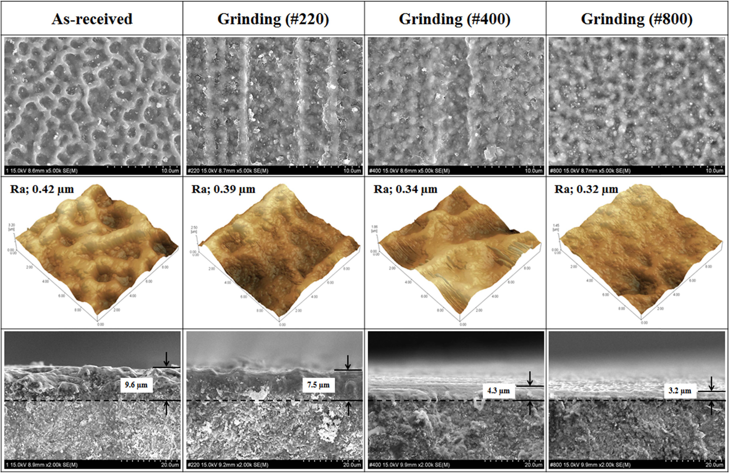
Fig. 6 shows the surface microstructure and morphology
of the coating layers fabricated by room temperature spray processing as a
function of surface-grinding. No delamination or micro-cracks were observed in
the coating layer or at the interface between the coating and substrate. All
coating layers were composed of nanoscale 3Y-TZP particles in the range of 50
to 200 nm. Homogeneous surface microstructure and coating thickness was
obtained for all substrates, but coating morphology and thickness were
dependent on the texture of the substrate surface after grinding. Coated
microstructure showed a three dimensional network or a wave-like pattern in the
as-sintered specimens as well as those obtained by fine grinding by
#800 SiC abrasive; however, large difference in surface roughness
were noted between the two coating layers. From the analysis of AFM images,
maximum value of Ra (0.42 µm) was obtained for the coating layer of the
as-sintered substrate; in contrast, minimum value of Ra (0.32 µm) was obtained
from the coating layer of the specimen obtained by fine surface-grinding using
#800 SiC abrasive.
Vertical lines were observed in the coated layers of the
substrates with large scale scratches fabricated using #220, #400
SiC abrasive. In these specimens, coated morphology was similar to the vertical
patterns on the substrate surface. The Ra of the coated layers gradually
decreased from 0.42 µm to 0.32 µm with a decrease in the surface roughness of
the substrate, indicating that highly roughened substrate is the main factor
for obtaining a highly roughened coating layer.
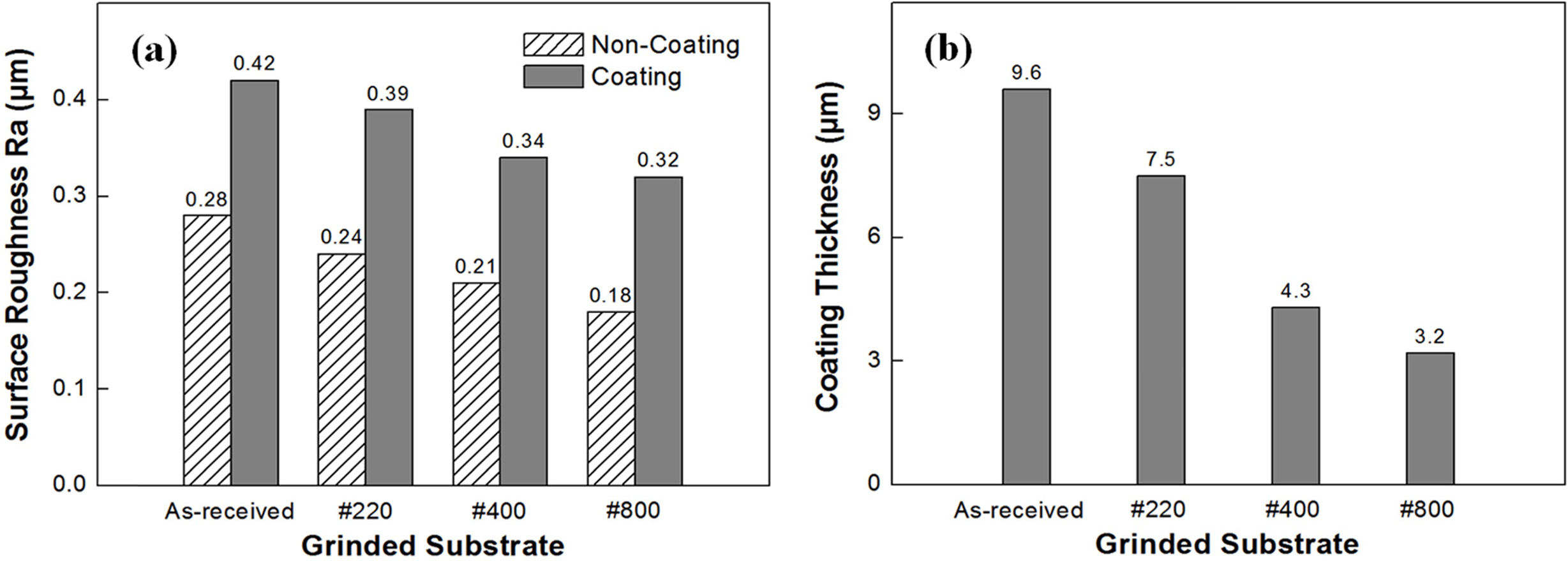
Fig. 7 shows the coating thickness and the surface
roughness of the coated layer. The Ra of the coating layer can be calculated
from the average value of the linear roughness data along the horizontal and
vertical lines in the AFM map [25]. Coating thickness and surface
roughness of the coated layer were also dependent on the substrate roughness
based on the type of surface-grinding. Maximum coating thickness of 9.6 µm was observed
for the coating layer of the as-sintered substrate. Conversely,
minimum coating thickness of 3.2 µm was obtained for the coating layer of the
substrate ground using #800 SiC abrasive.
|
Fig. 2 Characterization of coating powder after calcination; (a) particle morphology, (b) agglomeration size distribution and (c) phase composition. |
|
Fig. 3 Characterization of the as-sintered 3Y-TZP substrate before surface-grinding; (a) surface microstructure as per SEM, (b) surface morphology as per AFM, and (c) phase composition. |
|
Fig. 4 Planar microstructure by SEM and surface morphology by AFM of 3Y-TZP substrates after surface-grinding. |
|
Fig. 5 Optical photographs and phase analysis of 3Y-TZP coatings as a function of deposition cycle and the type of surface-grinding; (a) color of coated layer and (b) phase composition. |
|
Fig. 6 Characterization of coated 3Y-TZP morphology by room temperature spray processing observed by SEM and AFM with respect to the type of substrate surface-grinding. |
|
Fig. 7 Variations in (a) surface roughness determined via AFM images and (b) coating thickness determined from perpendicular images of SEM. |
Zirconia substrate was coated by zirconia particles by
spraying process at room temperature to improve the bone-bonding ability and
cell adhesion of zirconia dental implants by enhancing the surface roughness of
the as-obtained specimens. The influence of substrate surface-grinding
on the surface roughness of the coating surface was also
investigated. Large and small scratches were induced on the
zirconia substrate through surface-grinding by SiC abrasive,
but the process resulted in decreased substrate roughness. Dense and
homogeneous coatings composed of tetragonal zirconia grains were formed on the
zirconia substrate by room temperature spray processing and coating morphology and
thickness were dependent on the substrate roughness and surface
texture obtained by abrasive grinding. Maximum Ra of 0.42 µm and film thickness
of 9.6 µm of the coated layer was obtained for the as-sintered substrate
with maximum substrate roughness, indicating that a
highly roughened coating layer adhered to the highly
roughened substrate. In contrast, minimum surface roughness
(Ra; 0.32 µm) and film thickness (3.2 µm) of the coated layer were obtained
from the fine grinded substrate with minimum substrate roughness.
This work was supported by a National Research Foundation
of Korea (NRF) grant funded by the Korea government (MEST) (Grant No.
2018-019041).
- 1. H. Nishihara, M.H. Adanez, and W. Att, J. Prosthodont. Res. 63[1] (2019) 1-14.
-

- 2. H. Tong, C.B. Tanaka, M.R. Kaizer, and Y. Zhang, Ceram. Int. 42[1] (2016) 1077-1085.
-
- 3. C. Gautam, J. Joyner, A. Gautam, J. Rao, and R. Vajtai, Dalton. Trans. 45[48] (2016) 19194-19215.
-
- 4. A. Apratim, P. Eachempati, K.K.K. Salian, V. Singh, S. Chhabra, and S. Shah, J. Int. Soc. Prev. Community. Dent. 5[3] (2015) 147-156.
-
- 5. E.S. Elshazly, S.M. El-Hout, and M.E.S. Ali, J. Mater. Sci. Technol. 27[4] (2011) 332-337.
-
- 6. I. Denry, and J.A. Holloway, Mater. 3[1] (2010) 351-368.
-
- 7. Y.R. Fonseca, C.N. Elias, S.N. Monteiro, H.E.S dos Santos, and C. Santos, Mater. 12[16] (2019) 2529.
-
- 8. F. Rupp, L. Liang, J. Geis-Gerstorfer, L.Scheideler, and F. Hüttig, Dent. Mater. 34[1] (2018) 40-57.
-
- 9. Z. Özkurt, and E. Kazazoğlu, J. Oral. Implantol. 37[3] (2011) 367-376.
-
- 10. M. Andreiotelli, H.J. Wenz, and R.J. Kohal, Clin. Oral. Impl. Res. 20[4] (2009) 32-47.
-
- 11. P.F. Manicone, P.R. Iommetti, and L. Raffaelli, J. Dent. 35[11] (2007) 819-826.
-
- 12. R. Depprich, C. Naujoks, M. Ommerborn, F. Schwarz, N.R. Kübler, and J. Handschel, Clin. Implant. Dent. Relat. Res. 16[1] (2014) 124-137.
-
- 13. Y. Zhang, and B.R. Lawn, J. Biomed. Mater. Res. Part B Appl. Biomater. 72B[2] (2005) 388-392.
-
- 14. G. Soon, B. Pingguan-Murphy, K.W. Lai, and S.A. Akbar, Ceram. Int. 42[11] (2016) 12543-12555.
-
- 15. M.R. Towler, I.R. Gibson, and S.M. Best, J. Mater. Sci. Lett. 19[24] (2000) 2209-2211.
-
- 16. L. Le Guéhennec, A. Soueidan, P. Layrolle, and Y. Amouriq, Dent. Mater. 23[7] (2007) 844-854.
-
- 17. M. Guazzato, M. Albakry, L. Quach, and M.V. Swain, Biomaterials. 25[11] (2004) 2153-2160.
-
- 18. K. Pardun, L. Treccani, E. Volkmann, P. Streckbein, C. Heiss, G.L. Destri, G. Marletta, and K. Rezwan, Mater. Sci. Eng. C. 48 (2015) 337-346.
-
- 19. O.E. Ogle, Dent. Clin. North Am. 59[2] (2015) 505-520.
-
- 20. H.J. Kim, J.J. Kim, and J.K. Lee, J. Nanosci. Nanotechnol. 19[10] (2019) 6285-6290.
-
- 21. D. Hanft, J. Exner, M. Schubert, T. Stöcker, P. Fuierer, and R. Moos, J. Ceram. Sci. Technol. 6[3] (2015) 147-182.
-
- 22. J. Akedo, Mater. Sci. Forum. 449-452 (2004) 43-48.
-
- 23. Y. Imanaka, and J. Akedo, in Proceedings of the 54th Electronic Components and Technology Conference, April 2004, edited by IEEE (Institute of Electrical and Electronics Engineers, 2004) p. 1614.
-
- 24. J. Akedo, J. Therm. Spray. Technol. 17[2] (2008) 181-198.
-
- 25. D.W. Lee, and S.M. Nam, J. Ceram. Process. Res. 11[1] (2010) 100-106.
 This Article
-
2020; 21(S1): 68-73
Published on May 31, 2020
- 10.36410/jcpr.2020.21.S1.s68
- Received on Dec 16, 2019
- Revised on Apr 16, 2020
- Accepted on May 4, 2020
Services
- Abstract
introduction
experimental details
results and discussion
conclusions
- Acknowledgements
- References
- Full Text PDF
Shared
Correspondence to
- Jong Kook Lee
-
Department of Advanced Materials and Engineering, Chosun University, Gwangju 61452, Korea
Tel : +82-62-230-7202
Fax: +82-62-608-5402 - E-mail: jklee@chosun.ac.kr
Clean-Energy Research Institute(CRI), Hanyang University, 222, Wangsimni-ro, Seongdong-gu, Seoul, 04763, Korea
E-mail: jcpr@hanyang.ac.kr