


- Enhancement of surface roughness of zirconia substrate by slurry coating
Woo Chang Kim and Jong Kook Lee*
Department of Materials Science and Engineering, Chosun University, Gwangju 61452, Korea
In order to increase the bone
bonding-ability and biocompatibility of zirconia-based implants, the surface
roughness must be high. In this study, we tried to improve the surface
roughness of the zirconia substrates by surface modification using two types of
zirconia slurry and spin coating. We also investigated to the effect of
repeated coating times on the surface roughness of coating layer. Coating
layers fabricated by slurry and spin coating showed uniform thickness and dense
microstructure. As increasing the repeated coating times, the thickness of
coating layer gradually increased from 0.7 to 1.7 μm in case of small particles
or from 0.9 to 2.0 μm in case of large particles. Slurry containing small
particles (~ 40 nm) had low viscosity and good forming-ability of coating
films, but the improvement of surface roughness by slurry coating was not high.
Roughness enhancement on coated layer in zirconia slurry containing large
particles (~100nm) was higher than that of small particles at the same
processing condition. In this study, 4 times coating specimen showed maximum
surface roughness of Ra 0.36 μm in 3Y-TZP powder containing large particles, or
Ra 0.27 μm in that of small particles.
Keywords: Zirconia Slurry, Solid loading, Spin coating
Zirconia ceramics have promising mechanical properties,
including corrosion resistance, wear resistance and high stability and it is a
representative ceramic material in various industries [1, 2]. Excellent wear
resistance and high fracture toughness of the ceramic materials
applied to hip implant balls, bearings, grinding ball and various
wear resistant structural materials [3-6]. Additionally, zirconia is white with
high light transmittance, low sensitivity to plaque formation, and excellent
biocom- patibility, suggesting the utilization of
dental implant applications [7-10]. Zirconia materials are also used as oxygen
sensor and solid fuel cell material by utilizing ion
conductivity through oxygen vacancies and is suitable for
manufacturing various ceramic related components [11].
Recently, zirconia-based bioceramics are widely used as
implant materials because of their effective biological properties
such as biocompatibility, minimizing ion release, and low affinity to bacterial
colonization [12, 13]. Of the zirconia ceramics, 3mol% yttria stabilized
tetragonal ziconia polycrystals (3Y-TZP) is frequently used as a main material
for dental ceramic implants. It is also widely studied as a substitute material
for titanium implant due to its high refractive index, light transmittance and
aesthetics.
Enhanced mechanical and biological properties can be
improved by optimizing sintering processes and after surface treatment [14].
3Y-TZP ceramics has biological bioinertness and shows easy failure during implantation
due to the limit of direct bonding between implant and human bone [15-17]. In
order to further increase the bone bonding strength and
biocompatibility of such zirconia- based implants, surface
modification of implants is required [18-20]. The sol-gel and powder slurry
coating methods can be manufactured the surface coating of
zirconia implant through an inexpensive and simple process, enhancing the bone
cohesion and biocompatibility by improving surface roughness [21-22]. Slurry
coating provides a relatively thick coating layer and could be controlled the
thickness by repeated coating times, and is available to obtain the optimal
surface properties for the good induction of bone adhesion during the initial
period after implantation. Additionally, thick coating layer from slurry
coating process has an advantage to use for long periods due to the relatively
slower dissolution rate [23].
The preparation of aqueous slurry is most important in the
ceramic slurry coating process, and it should be controlled the slurry pH,
dispersant content and solid loading in order to produce a stable
and high production efficiency. Sometimes, to supplement the slurry dip
coating or sol-gel dip coating, spin coating is used to apply the coating
uniformity and dense coating layer. In general, the spin coating is thinly
spread on the substrate by the high-speed rotational movement on the substrate
to form a coating layer [24-26].
In this study, two types of 3Y-TZP powder with different
particle size were used to obtain the 3Y-TZP coating with high surface
roughness through the spin coating of aqueous slurry. We also have an
expectation to form a uniform and dense coating layer by this surface
modification, which improves the bone bonding strength
and biocompatibility of zirconia ceramics. In this process, we tried to control
the surface microstructure and roughness by change of slurry parameters,
i.e. particle type of 3Y-TZP and coating times, and investigated the dependence
of processing factors to coating surface and microstructural
evolution.
Two sizes of commercial 3Y-TZP powder were used for
zirconia slurry preparation. Powder properties about particle morphology, phase
composition and particle size distribution were characterized, and compared to
the influence on the slurry and coating properties. Slurry preparation
condition obtained from preliminary experiments was used, such as
pH 12, 1 wt.% dispersant (Darvan C), and 40 wt.% solid
loading. Two types of nanoscale 3Y-TZP powder (40 and 100 nm diameter) were
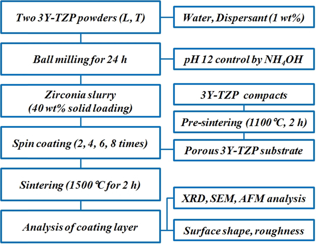
used to prepare the zirconia slurry through ball milling for 24 h as shown in
Fig. 1. Considering the slurry fluidity and coating thickness, the content of
solid loading of 3Y-TZP powder was fixed to 40 wt.%, determined from the
previous results [27].
The 3Y-TZP substrate for slurry coating was fabricated a
disc-type porous specimen by uniaxial pressing and pre-sintering at 1,100 °C
for 2 h. Using a spin coater, zirconia slurry was coated on the pre-sintered
3Y-TZP porous specimen, and repeated a spin coating after drying. Maximum
coating times at solid loading of 40 wt.% was limited to 8 on the
same substrate, considering the variation of surface roughness.
Final sintering after coating was carried out at 1,500 °C
for 2 h. Coated microstructure and surface morphology including surface
roughness were observed by Scanning Electron Microscope (SEM) and Atomic Force Microscope (AFM), and analyzed the
surface microstructure and coating thickness with powder type and coating
times. Of the surface parameter from AFM images, the value of Ra (center line average) was selected as a representative parameter of surface roughness.
Finally we investigated the influence of processing factors to the surface
properties of coated layer.
|
Fig. 1 Schematic flowchart for the experimental procedure. |
Two types of 3Y-TZP commercial powders with different
particle size were used as raw materials for the slurry preparation and their
microstructural morphology and agglomeration characterization
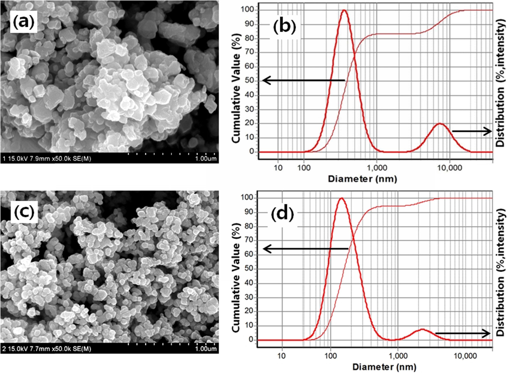
via particle size distribution analysis were shown in Fig. 2. The
first powder containing large scale particles (noted to L powder) showed a
severe agglomeration (larger agglomerate size and more secondary
agglomerate) and large primary particle size (about 100 nm). The second powder
containing small scale particles (note to T powder) is small primary particle
size (about 40 nm) and weak agglomeration characteristics. From the analysis of
particle size distribution as shown in Fig. 2(a), L powder
consists of 83% primary aggregates of 232 nm and 17% secondary aggregates of
2.5 μm. Comparatively, T powder is composed of 94% primary aggregates of 197 nm
and 6% secondary aggregates of 1.6 μm.
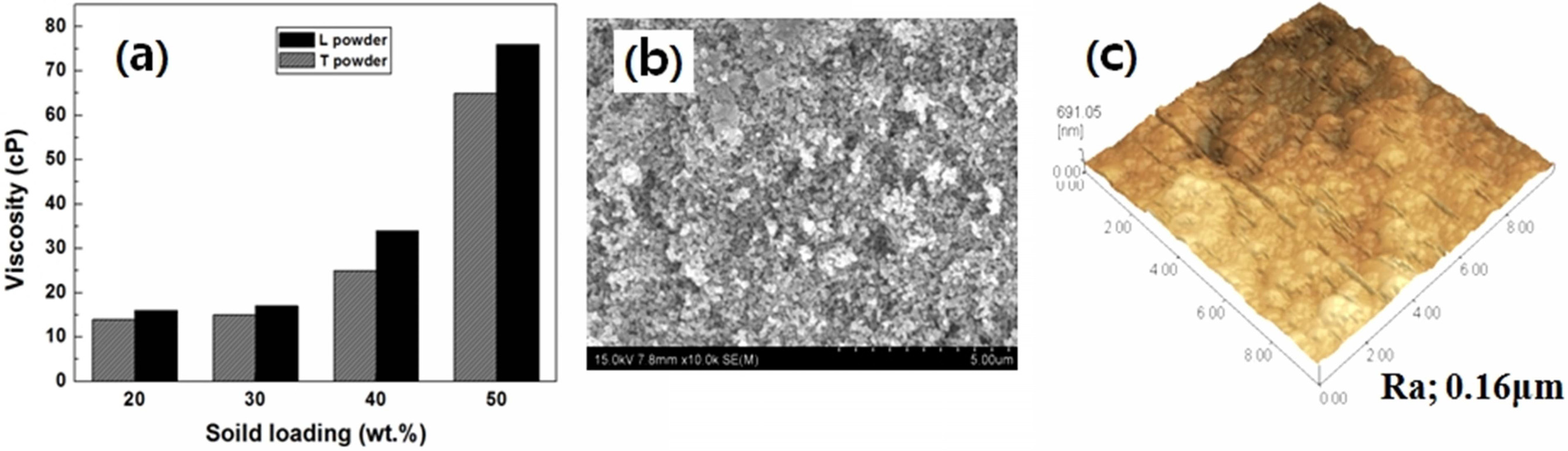
Fig. 3(a) shows the slurry viscosity at pH 12 as a
function of solid loading prepared by mixing and milling of 3Y-TZP powder,
distilled water, dispersant and pH control agent. With increasing the solid
loading of 3Y-TZP powder, slurry viscosity was gradually increased regardless
of powder type. But the slurry including 50wt.% solid loading had high
viscosity over 60 cP, which was limited to carry out the spin coating due to
the less fluidity of slurry. So, solid loading was fixed to 40 wt.% in this
experiment, considering a coating efficiency for a
forming-ability of 3Y-TZP thick film. Slurry viscosity for L or T
powder containing 40 wt.% solid loading indicated the proper range (about 36
and 27 cP, respectively) for spin coating, and L powder slurry had higher
viscosity than that of T powder due to the large particle size and severe
agglomeration.
Fig. 3(b) and (c) show the surface microstructure and
morphology for zirconia substrate observed by SEM and AFM. Pre-sintered 3Y-TZP
substrate at 1,100 °C for 2 h
shows porous microstructure with grain size of 175 nm and apparent density of 90%.
Porous structure of substrate surface enhances the slurry coating by the
capillary force of open pores. From the analysis of AFM images, porous 3Y-TZP
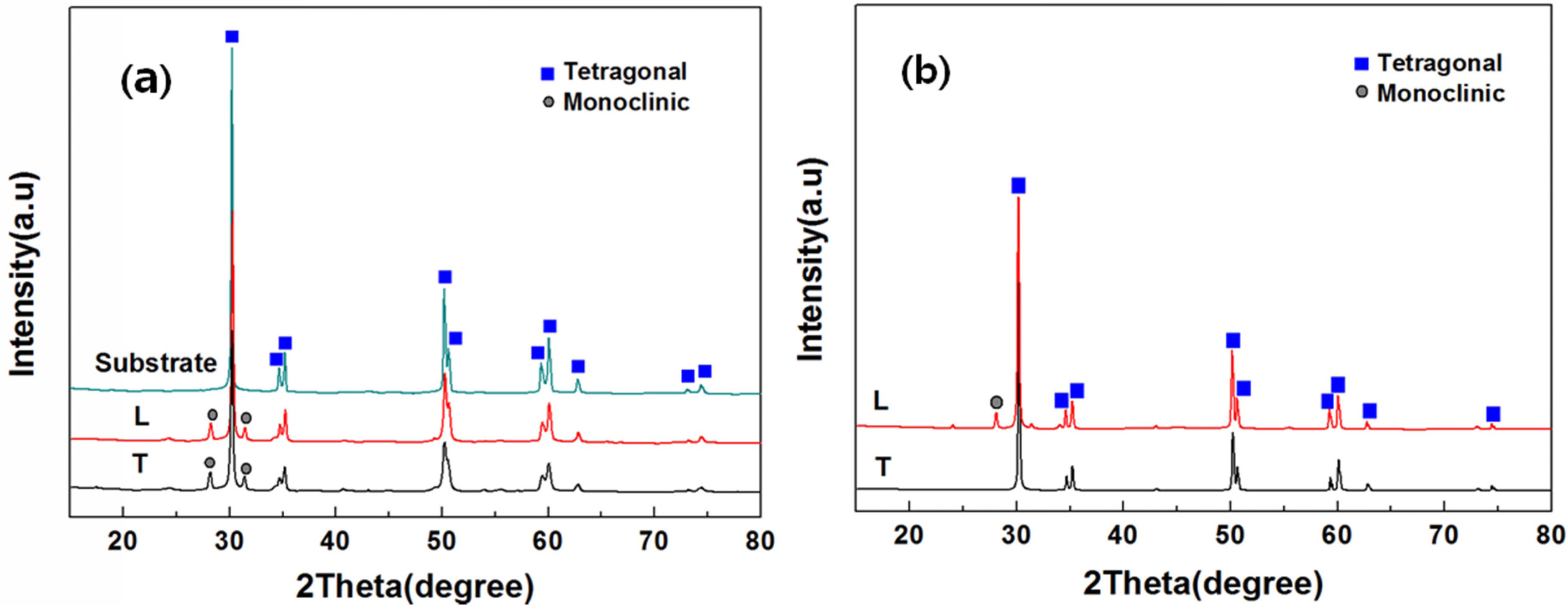
substrate had roughened surface (Ra; 0.16 μm). Phase composition of two types
of 3Y-TZP powder and pre-sintered substrate presents in Fig. 4(a), indicating a
main tetragonal phase and a little minor monoclinic phase in commercial two
powders. Phase composition of coated layer after a spin coating and sintering
at 1,500 °C for 2 h was slightly different from each other as shown in
Fig. 4(b). Coated layer fabricated from L powder indicates a main tetragonal
phase and a small quantity of monoclinic phase. The partial existence of
monoclinic phase on coating surface is due to the severe agglomeration and the growth
of a few large grains during sintering. On the other hand, coated zirconia
layer by T powder composed of all tetragonal grains, because of small particles
and densification due to the sintering at high temperature.
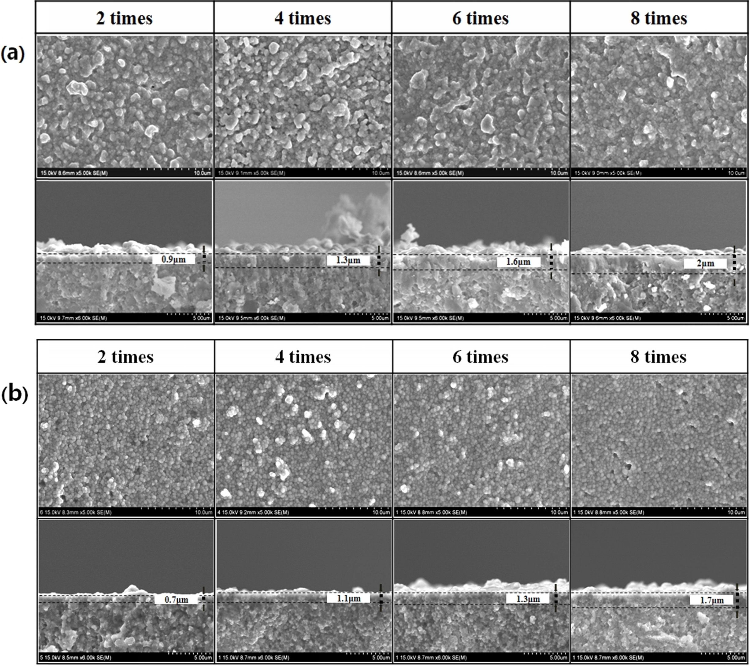
Fig. 5 shows the surface microstructure and perpen- dicular fractured surface of coated layer
after the post-sintering at 1500°C for 2 h. 3Y-TZP coated films are homogeneous
surface microstructure and uniform thickness, but it depends on
the powder type and coating times. In 3Y-TZP coated surface
layer fabricated from L powder, the growth of large scale grains was evident
and resulted to large average grain size of 650 nm, irrespective of coating
times, and the thickness of coating layer was gradually increased from 0.9 to
2.0 μm with increasing coating times. In contrast, coated surface layer
fabricated from T powder, small scale grains were mainly observed on surface
microstructure, indicating the grain growth inhibition during sintering by soft
agglomerates, and resulted to small average grain size of 300 nm. The thickness
of coating layer in this powder was also gradually increased from 0.7 to 1.7 μm
with increasing coating times.
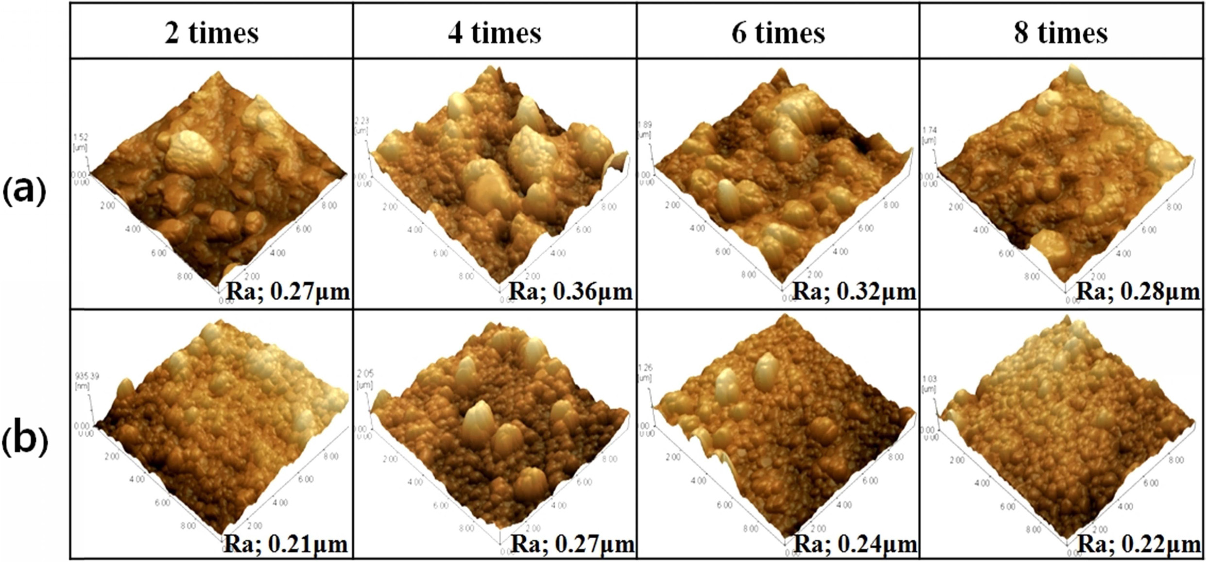
Surface morphology and roughness analyzed from AFM images
were dependent on the powder type and coating times. In comparison
with substrate morphology, some protruding particles as like a
mountain-like shape were observed on coated surface, which number and size were
dependent on the type of powder and coating times. Protruding particles formed
from L powder in Fig. 6 are larger than that of T powder, meaning that it
related with the particle size of starting powder. The number of
protruding particles on coated surface showed the maximum
value in 4 times coating specimen, compared with less protruding particles in 2
or 8 times coating specimen. It suggested that the formation and surface
appearance of protruding particles were related with the particle deposition
during spin coating, that is, particle compaction and arrangement
at repeated coating. As shown in AFM images, the number of protruding
particles was increased to 4 time coatings in both types of 3Y-TZP powder, but
they partially disappeared from the coated surface in 6 or 8 coatings
specimen. It means that the formation and surface appearance of protruding
particles were related with particle adhesion, dispersed arrangement and
filling up on planar substrate surface during repeated coating. So it resulted
that the size and number of protruding particles were directly affected to the
surface roughness of coated surface.
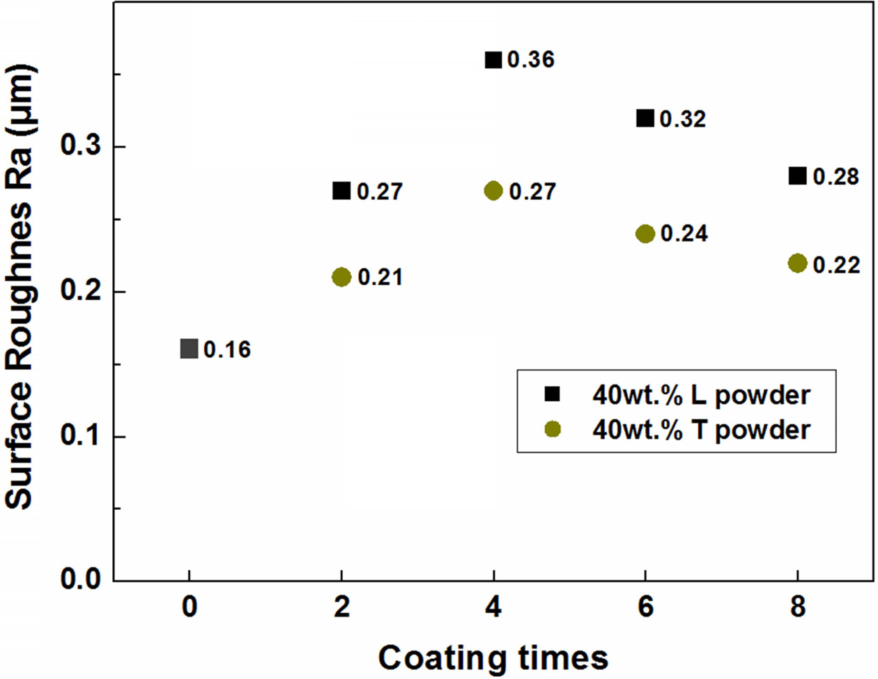
From the investigation of the relation with coating times
and surface roughness on coated surface, 4 times coating specimen showed
maximum surface roughness (Ra 0.36 μm in L powder, Ra 0.27 μm in T powder) in
both types of 3Y-TZP powder as shown in Fig. 7. Also, surface roughness of
coated layer from L powder was higher than that of T powder due to the rough
surface by large protruding particles, regardless of coating times.
|
Fig. 2 Particle morphology and particle size distribution analysis of two types of 3Y-TZP commercial powder; (a), (b) L powder, and (c), (d) T powder. |
|
Fig. 3 Characteristics of slurry viscosity and surface morphology of 3Y-TZP substrate; (a) viscosity variation with solid loading of two types of 3Y-TZP powders, (b) porous microstructure of 3Y-TZP substrate and (c) surface morphology by AFM observation. |
|
Fig. 4 Phase composition of (a) two types of starting 3Y-TZP powder and pre-sintered substrate, and (b) coated surface after slurry coating. |
|
Fig. 5 Variation of surface microstructure and film thickness on coated layer with powder type and coating times; (a) L powder, (b) T powder. |
|
Fig. 6 Variation of surface morphology and roughness on coated layer with powder type and coating times; (a) L powder, (b) T powder. |
|
Fig. 7 Dependence of surface roughness (Ra) on the powder type and coating times. |
Zirconia slurry coatings were fabricated by spin coating
using two sizes of commercial powder to enhance the surface roughness of 3Y-TZP
substrate. Sintered coating layer with homogeneous microstructure,
uniform thickness and high compactness could be obtained from
spin coating of slurry, but physical properties of coated layer were dependent
on the particle size in slurry and coating times. The coating
thickness gradually increases with repeated coating times, but surface roughness
of coated surface is dependent on the powder type
and repeated coating times. Slurry coating containing large
particles is more effective to improve the substrate roughness
than that of small particles. We also confirmed that repeated slurry coating is
available to increase the surface roughness of 3Y-TZP substrate, but limits the
maximum roughness by the coating time due to the appearance condition of
protruding particles on substrate surface. In this experiment, 4 times coating
specimen showed maximum surface roughness (Ra 0.36 μm in L powder, Ra 0.27 μm
in T powder) in both types of 3Y-TZP powder.
This work was supported by the National Research
Foundation of Korea (NRF) grant funded by the Korean government (MEST) (No.
2018-019041).
- 1. P. F. Manicone, I. P. Rossi, and L. Raffaelli, J. Dent. 35[11] (2007) 819-826.
-

- 2. R. B. Osman, and M. V. Swain, Mater. 8[3] (2015) 932-958.
-
- 3. J. Chevalier, and L. Gremillard, J. Am. Ceram. Soc. 92[9] (2009) 1901-1920.
-
- 4. M. Hisbergues, S. Vendeville, and P. Vendeville, J. Biomed. Mater. Res. Part B: Appl. Biomater. 88B[2] (2009) 519-529.
-
- 5. V. Lughi, and V. Sergo, Dent. Mater. 26[8] (2010) 807-820.
-
- 6. M. Stimmelmayr, S. Sagerer, K. Erdelt, and F. Beuer, Int. J. Oral. Maxillofac. Implants. 28[2] (2013) 488-493.
-
- 7. I. Denry, and J.R. Kelly, Dent. Mater. 24[3] (2008) 299-307.
-
- 8. S. Zinelis, A. Thomas, K. Syres, N. Silikasand, and G. Eliades, Dent. Mater. 26[4] (2010) 295-305.
-
- 9. L. Rimondini, L. Cerroni, A. Carrassi, and P. Torricelli, Int. J. Oral. Maxillofac. 17[6] (2002) 793-798.
- 10. I. Denry, Dent. Mater. 29[1] (2013) 85–96.
-
- 11. L. D. Liu, Y.H. Cheng, and W.C.J. Weic, J. Ceram. Process. Res. 20[4] (2019) 347-356.
- 12. A. Scarano, F.D. Carlo, M. Quaranta, and A. Piattelli, J. Oral. Implantol. 29[1] (2003) 8-12.
-
- 13. L. Sennerby, A. Dasmah, B. Larsson, and M. Iverhed, Clin. Implant. Dent. Relat. Res. 7[1] (2005) 13-20.
-
- 14. Y. I. Kim, S. H. Sung, S. M. Lee, S. H. Lee, B. S. Lim, J. S. Byun, C. Y. Hyun, Y. Hwang, and J. W. Byeon. J. Ceram. Process. Res. 13[1] (2012) s31-s36.
- 15. A. Afzal, Mater. Express. 4[1] (2014) 1-12.
-
- 16. J. Chevalier, Biomater. 27[4] (2006) 535-543.
-
- 17. H. J. Wenz, J. Bartsch, S. Wolfart, and M. Kern, Int. J. Prosthodont. 21[1] (2008) 27-36.
- 18. M. Gahlert, T. Gudehus, S. Eichhorn, E. Steinhauser, H. Kniha, and W.Erhardt, Clin. Oral. Implants. Res. 18[5] (2007) 662-668.
-
- 19. G. Soon, B. Pingguan-Murphy, K.W. Lai, and S.A. Akbar, Ceram. Int. 42[11] (2016) 12543-12555.
-
- 20. S. Roedel, J. C. M. Souza, F. S. Silva, J. Mesquita-Guimarães, M. C. Fredel, and B. Henriques, Ceram. Int. 44[11] (2018) 12496-12503.
-
- 21. D. Yamashita, M. Machigashira, M. Miyamoto, H. Takeuchi, K. Noguchi, Y. Izumi, and S. Ban, Dent. Mater. J. 28[4] (2009) 461-470.
-
- 22. R. Mai, C. Kunert-Keil, A. Grafe, T. Gedrange, G. Lauer, M. Dominiak, and T. Gredes, Ann. Anat. 196[6] (2012) 561-566.
-
- 23. H. W. Kim. H. E. Kim, and J. C. Knowles, J. Biomed. Mater. Res. B: Appl. Biomater. 70[2] (2004) 270-277.
-
- 24. C. Agrafiotis, A. Tsetsekou, and I. Leon, J. Am. Ceram. Soc. 83[5] (2000) 1033-1038.
-
- 25. J. C. Kim, D. Y. Lee, H. R. Kim, H. W. Lee, J. H. Lee, and J. W. Son, Thin. Solid. Films. 519[8] (2011) 2534-2539.
-
- 26. M. Norouzi, and A. A. Garekani, Ceram. Int. 40[2] (2014) 2857-2861.
-
- 27. D. S. Kim, and J. K. Lee, J. Nanosci. Nanotechnol. 19[2] (2019) 1118-1121.
-
 This Article
-
2020; 21(S1): 41-46
Published on May 31, 2020
- 10.36410/jcpr.2020.21.S1.s41
- Received on Dec 16, 2019
- Revised on Apr 16, 2020
- Accepted on May 4, 2020
Services
- Abstract
introduction
experimental details
results and discussion
conclusions
- Acknowledgements
- References
- Full Text PDF
Shared
Correspondence to
- Jong Kook Lee
-
Department of Materials Science and Engineering, Chosun University, Gwangju 61452, Korea
Tel : +82 62-230-7202
Fax: +82 62-608-5402 - E-mail: jklee@chosun.ac.kr
Clean-Energy Research Institute(CRI), Hanyang University, 222, Wangsimni-ro, Seongdong-gu, Seoul, 04763, Korea
E-mail: jcpr@hanyang.ac.kr