


- Cu3Se2 counter electrode with rGO interlayer by pulsed electrodeposition for quantum dot-sensitized solar cells
Yong-Han Yun, In-Rok Jo, Young-Hoon Lee, Vu Hong Vinh Quy and Kwang-Soon Ahn*
School of Chemical Engineering, Yeungnam University, Gyeongsan 712-749, Republic of Korea
We synthesized a reduced
graphene oxide/copper selenide (rGO/Cu3Se2) cumulative
structure on a fluorine doped tin oxide (FTO) conducting glass substrate. The
pulsed electrodeposition method was used to construct the rGO and Cu3Se2
nanostructures. During rGO deposition, pulsed electrodeposition resulted in a
uniform film on the FTO. Deposited rGO with surface defects can act as an
active site for Cu3Se2 growth. In the case of Cu3Se2,
pulsed electrodeposition contributed to its uniform stoichiometry and porous
structure. This porosity affected the efficient diffusion of liquid
electrolytes toward the counter electrode surface and resulted in high power
conversion efficiency. In addition, the rGO interfacial layer served as
electron shuttle, directly prohibited the recombination path between the FTO
and electrolyte and enhanced the fill factor (FF). As a result, the FTO/rGO/Cu3Se2
electrodes with CdS/CdSe/ZnSe QD photoanodes achieved a power conversion
efficiency of 3.622%, which was a significant improvement over the 2.997%
efficiency of direct-deposited FTO/Cu3Se2 electrodes with
the same photoanodes.
Keywords: Quantum dot-sensitized solar cells, Reduced graphene oxide, Copper selenide, Pulsed electrodeposition, Counter electrode
Quantum Dot-sensitized Solar Cells (QDSSCs) are third
generation solar cells that have the potential to overcome the
Shockely-Queisser limit in the power conversion efficiency (PCE) of Si-based
solar cells [1]. They have a similar structure to dye-sensitized solar cells,
but the dyes are replaced with inorganic quantum dots (QDs). A
QD photosensitizer has more advantageous and unique
properties than organic dyes, including a size dependent band gap, hot carrier
injection, and multiple exciton generation. [2-4]. Most studies on QDSSCs have
focused on enhancing the performance of photoanodes to improve its
light absorbing efficiency and electron injection and
preventing recombination [5-7]. However, despite their importance, there
remains an insufficient number of studies on counter electrode materials. As
part of the QDSSC, the counter electrode plays an important role in the
reduction of electrolytes and maintenance of the polysulfide electrolyte
condition [3]. Even though the photoanode displays sufficient performance,
completion of QDSSC operations requires a stable and
efficient counter electrode [8, 9]. However, stable counter electrodes with
polysulfide are a con- tentious issue [10-12].
Most of the known materials used for counter electrodes exhibit
only limited stability against polysulfide electrolytes
[4]. It is for this reason that many researchers continue to
investigate stable counter electrode materials. Among them,
metal chalcogenides are a promising material for counter electrodes owing to
their good bulk conductivity and electrocatalytic properties [13]. To enhance
stability, some researchers have suggested that a combination with a carbon
based material is effective. [9] Reduced graphene oxide (rGO),
in particular, has arisen as the most prominent candidate
[14, 15]. The rGO has been investigated by many researchers
owing to its higher conductivity than graphene oxide and
surface area. Furthermore, it is proved that rGO interfacial layer has benefit
when adopted at photoanode and counter electrode both [16-18]. Wang et al
adopted rGO layer between FTO and TiO2 film as interfacial layer to
prevent direct contact with electrolyte from CdS QD [16]. This rGO layer also
supports transportation of electron, can be exploited in opposite side. In case
of counter electrode application, Jie Ma et al exploited graphene aerogel for
using its extreme surface area to support MoS2 [17]. Wei Lu’s group
has studied direct synthesis of copper sulfides on rGO sheets. During
hydrothermal synthesis, Cu2S is embedded in rGO as nano particle and
GO is reduced into rGO. They spin coated rGO-CuS paste with
ethanol and PEG on FTO for counter electrode,
achieved 4.76% in PCE [19]. However, binder may
limit efficient diffusion of
electrolyte along the porous structure. Binder-assisted adhesion
also may cause instable conduction and degradation.
However electrochemical process can grow rGO and
active materials onto substrate directly. Under precise
control of deposition condition, electrochemically grown
crystals exhibits robust contact with substrate. Additionally, it is well known
that electro pulse-deposition (EPD) can induce unique results [20] and give a
uniform composition to the resulting product, such as a thin film on the
substrate [21]. To the best of our knowledge, there are only a few studies that
have applied both pulse-deposited copper selenide (Cu3Se2)
and rGO in order to fabricate counter electrodes for QDSSCs. Zeng et al. (2016)
made a thin lead selenide film on FTO using pulsed voltage deposition [22]. Ahn
et al. (2019) used a similar approach for nickel selenides [23].
In this study, we introduce pulsed electro-deposited rGO and Cu3Se2
electrodes for the counter electrodes of QDSSCs.
GO
preparation
Synthesis of graphene oxide (GO) was followed by the
Hummer’s method from literature [24]. One gram of graphite powder was mixed
with 23 ml of H2SO4 (concentrated, 95%) under ice bath
and mild stirring conditions. One gram of NaNO3 was dissolved in the
mixture after adequate dissolution. Three grams of KMnO4 was slowly
added in portion. The temperature was kept under 20 oC during
the addition of the KMnO4. The color of mixture turned from a
graphite grey/black to a dark green. After two hours of stirring under ice bath
conditions, 46 ml of deionized (D.I.) water was introduced into the mixture.
Simultaneously, the temperature of the mixture was kept under 98 oC.
At that point, vigorous stirring was performed for two hours. To
complete the reaction and eliminate excessive elements in
the mixture, 140 ml of D.I. water and 2 ml of H2O2 (30%)
were added. The color immediately changed to a bright yellow. After 15 min of
stirring, 250 ml of diluted 1 M HCl aqueous solution was added to
the mixture to dissolve any metallic by-products. After washing
with DI water three times and centrifugation, brown
precipitates were formed. By dissolving and dispersing the proper amount of
this product in D.I. water, 1 mg/ml of a GO solution was synthesized for
further use.
GO
and Cu-EDTA solution for electrodeposition of an rGO layer
An ethylenediaminetetraacetic acid (EDTA) capped copper
(Cu-EDTA) solution was made by following literature [22, 25]. Simply,
0.5954 g of EDTA was dissolved in 20 ml of D.I. water. This was followed with
0.128 g of NaOH to adjust the pH beyond 12. Then, 0.1996 g of CuSO4
was added. One milliliter of the Cu-EDTA solution was mixed with 39 ml of GO
solution. The prepared solution was stable after being kept in the dark under
ambient air conditions for a few days. Using the prepared solution, an rGO
layer was electrodeposited onto FTO. Detailed conditions of the
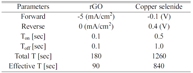
electrodeposition are described in Table 1.
Cu and Se precursor solution for electrodeposition
of a Cu3Se2 layer
To begin, 4.9937 g of CuSO4 and 2.2192 g SeO2
were used to prepare 0.2 M of a Cu and Se precursor solution. The pH value of
both solutions was adjusted to a value of 2 using H2SO4.
Twenty milliliters of each solution were mixed together to produce a final
volume of 40 ml. A solution containing the precursors was prepared and mixed
just before deposition. Milli-Q pure water was used as the solvent for each
solution. This prepared solution was used to deposit Cu3Se2
onto FTO and rGO modified FTO. Detailed conditions of the electrodeposition are
described in Table 1.
Photoanode
for QDSSC sensitized with QDs
Preparation of the photoanodes followed the conventional
successive ion layer adsorption and reaction (SILAR) method with slight
modifications [6, 26]. First, the FTO was prepared using a typical
cleaning method that utilizes successive ultra-sonication through acetone,
ethanol, and D.I. water, respectively. A TiO2 film was prepared by
the doctor-blading method with a TiO2 paste (Ti-Nanoxide T/SP, 20 nm
diameter, Solaronix SA) on the FTO substrate. TiO2 films on the FTO
were dried at 70 oC over 30 min and sintered at 450 oC
for 30 min under ambient air conditions. After sintering, the CdS and CdSe QDs
were decorated onto the TiO2 film by the SILAR method. The
preparation of Cd and S precursor solutions followed literature [6]. To begin,
0.1 M of Cd(NO3)2 was dissolved in ethanol and 0.1 M of
Na2S was dissolved in methanol. Each dipping process took one
minute, and five cycles were done for CdS. A similar procedure was performed
for CdSe. The preparation of Cd and Se precursor solutions also followed the
literature referenced above. First, 0.03 M Cd(NO3)2 was
dissolved in ethanol, while 0.03 M SeO2 and 0.06 M
NaBH4 were dissolved in ethanol. Selenium dioxide
solution caused the color to change from an opaque red to transparent after
stirring under sealed conditions. Each dipping took one minute, and seven
cycles were done for CdSe. The deposition of CdSe was conducted under inert Ar
gas conditions. Next, ZnSe was deposited by the SILAR method, where it acted as
a passivation layer for CdS/CdSe QDs [6, 7]. Then, 0.1 M Zn(NO3)2,
0.1 M SeO2, and 0.2 M NaBH4 were dissolved in ethanol.
Each cycle took one minute, and five cycles were done for ZnSe. After the SILAR
process, every photoanode was washed with ethanol and kept in the dark under
inert gas conditions for further use.
Material
characterization
The surface morphology and cross section of each sample
was observed by high-resolution scanning electron microscopy (HR-SEM; S-4800,
Hitachi LTD). The structure and crystallinity were characterized
through X-ray diffraction (XRD; MPD for thin
film, DIATOME). To investigate the surface atomic state and
confirm the atomic ratio, X-ray photo-electron spectroscopy (XPS; K-alpha,
Thermo Fisher Scientific) was conducted.
Device
performance characterization
Symmetrical dummy cells for the Tafel analysis and
electrochemical impedance spectra (EIS) were prepared by two identical counter
electrodes. The polysulfide electrolytes used in the symmetrical cells had the
same composition (2 M Sulfur, 2 M Na2S, and 0.2 M KCl) as the full
cell with a solvent composed of methanol and water (7:3 by volume) [12, 37,
38]. The active area of the symmetrical cell was 1.2 cm2 for every
sample and experiment. The Tafel polarization (WBCS3000, WONATECH)
was recorded from -0.5 V to 0.5 V at a scan rate of 10 mV/s. An EIS (ZIVE,
WONATECH) analysis was carried out to understand the electrochemical
reaction around the surface of the electrodes. The PCE was measured
under 1-sun illumination by solar simulator (PEC-L12
Solar Simulator, Peccell technology, Inc.) and potentiostat (Iviumstat.h, Ivium
technologies).
|
Table 1 Overview of pulsed electrodeposition parameters for preparation of rGO and copper selenide. |
Structure
and morphology
Reduced graphene oxide (rGO) and umangite copper selenide
(Cu3Se2) layers were successively deposited onto an FTO
substrate. The rGO-modified FTO had many surface defects [29] that provided
active sites for copper selenide growth. These sites may also provide different
orientations compared with direct deposition onto FTO. The
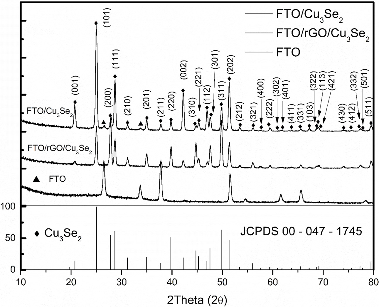
effect of rGO-modified FTO was confirmed via XRD.
According to Fig. 1, the Cu3Se2 on FTO displayed a
typical peak known as umangite (JCPDS 00-047-1745). The Cu3Se2
on rGO-modified FTO displayed a similar peak, but a difference in the peak
intensity was observed. This difference came from the presence of different
orientations due to the active sites provided by the rGO-modified FTO. The Cu3Se2
on FTO, (101) displayed the dominant peak along the FTO. It should be noted
that the deposited selenium induced the reduction of copper ions to form copper
selenide [30, 31]. However, on the rGO-modified FTO,
copper was already deposited on the surface of the rGO
[20, 25]. The Cu-EDTA-GO solution was used to deposit the rGO
and facilitated the presence of copper on the rGO as a metallic cluster. According
to the electrodeposition mechanism of copper selenide,
selenium is first deposited on the substrate followed by the reduction of the
copper ions [30].
When selenium was deposited onto Cu, the presence of the
copper contributed to different preferential orientations of the copper
selenide. This is likely the reason for the reversed intensity between the Cu3Se2
(200) and (111) at the Cu3Se2 on the rGO modified sample.
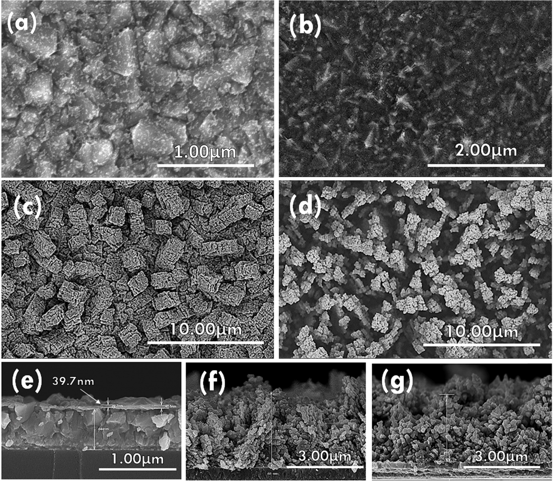
To understand the effect of surface modifications on the
morphology, SEM was conducted on each sample. Fig. 2 shows the top view and
cross-section of each sample. Fig. 2(a) shows a conventional Pt
electrode to compare with the other samples. Fig. 2(b) shows an
rGO-modified FTO. It is clear that the rGO uniformly covered the
FTO, and the copper clusters were regularly distributed
as well. From Fig. 2(c) and 2(d), the significant effects
of different substrates on the morphology can be seen. Fig.
2(c) shows a morphology that is vastly different from typical copper selenide
because of the pulsed electrodeposition technique [21]. During pulsed electrodeposition
in the forward condition, copper selenide was deposited onto FTO.
During the reverse condition, the precursor concentration at the interface was
restored to near the initial condition by mass transfer and diffusion. By
iterating this cycle, tiny pillars that aggregated into square–like columns
were grown. In Fig. 2(d), the Cu on the rGO provided more active sites than the
FTO, which led to a more porous film. This enhanced porosity may help
to diversify the paths available for the active mass transfer of
electrolytes. However, observations from Fig. 2(f) and (g) may
indicate that the growth mechanisms of each film are similar to that of other
work [21]. The height of the films on
the different substrates were not significantly different
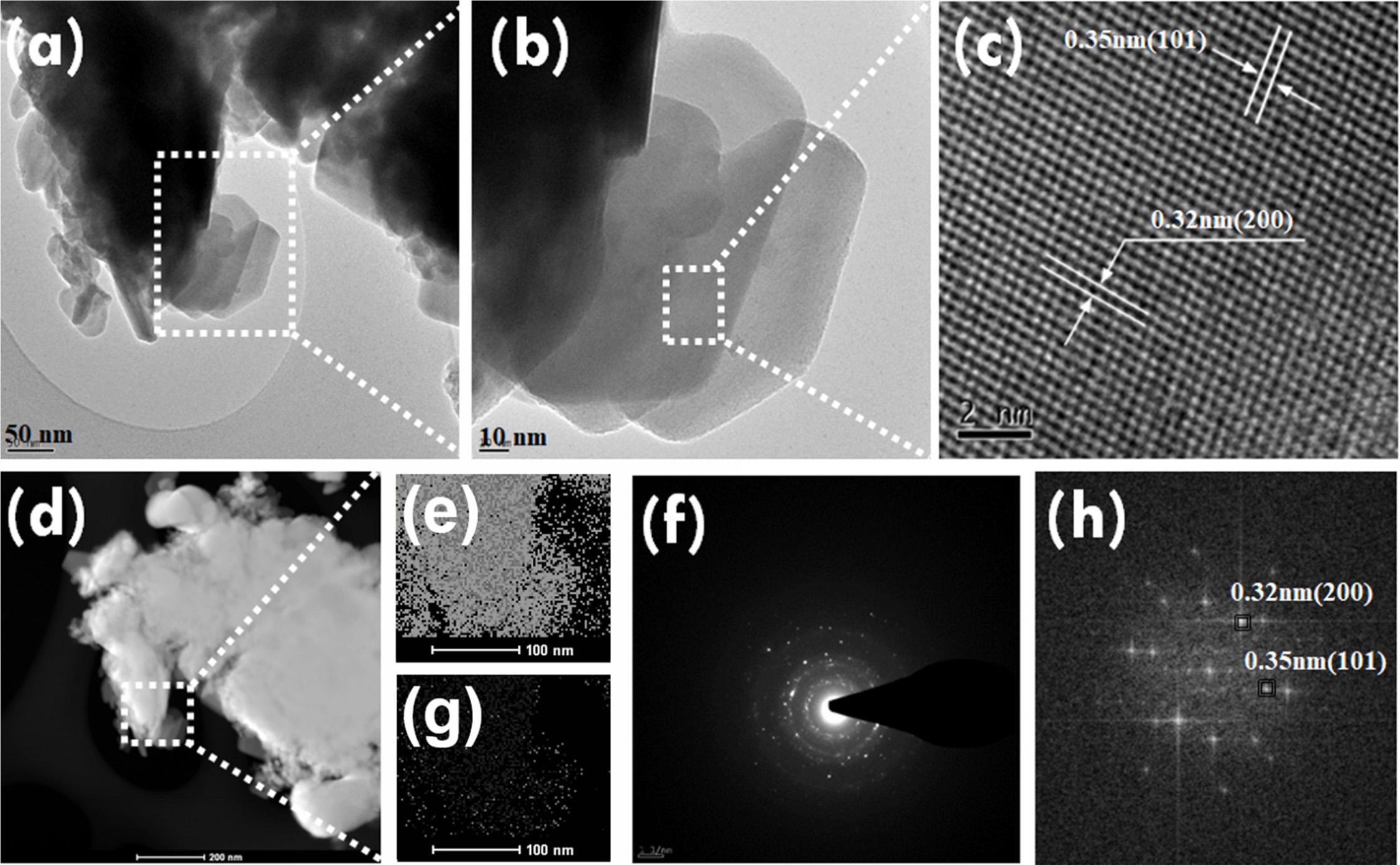
from each other. The microstructure of the rGO/Cu3Se2
sample was further investigated by transmission electron
microscopy (TEM). Fig. 3(a-c) show the crystalline
nature of Cu3Se2 on rGO. The results from Fig. 3(c)
confirmed (101) and (200) planes of umangite (JCPDS 00-047-1745), which
corresponded well to the results obtained via XRD. The loading densities of Cu3Se2
deposited on FTO and FTO/rGO were 0.3106 g/cm3 and 0.2938 g/cm3,
respectively.
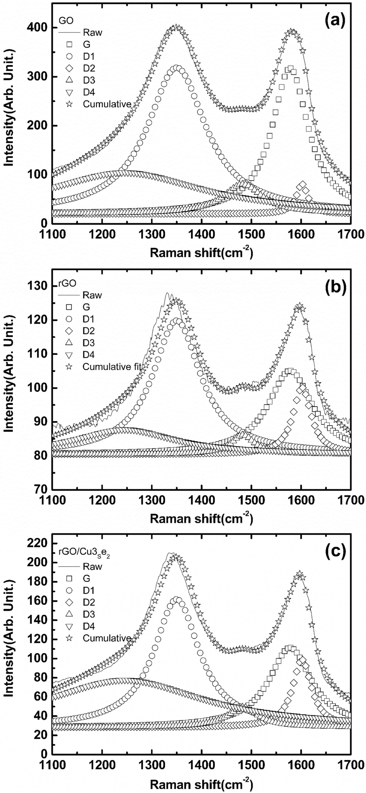
While Cu3Se2 has been well
characterized, there is still a lack of significant understanding of rGO. To
confirm the degree of reduction and existence of rGO on FTO, Raman spectroscopy
was used to measure each electrode. In Fig. 4(a), conventional D and G peaks
can be observed. This indicated that GO was successfully synthesized and well
oxidized [32, 33]. The deconvolution of Fig. 4(a) also corresponded to the
above prediction. Fig. 4(b) shows a diminished G peak, which indicated a
reduction of the oxygen containing group [39]. Fig. 4(c) shows similar results.
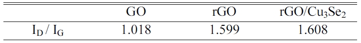
To verify the degree of reduction and other information, the D/G ratio was
calculated from the deconvoluted peaks [29, 33, 34]. Table 2 shows the D/G
ratios determined from the Raman spectroscopy of GO, rGO, and rGO/Cu3Se2
deposited FTO. The D/G ratio is an important index designating characteristic
for graphene and graphene-like materials. A larger D/G ratio indicates that a
smaller graphene oxide flake size was achieved [33]. It also indicates the
presence of more edge defect sites. An abundant number of defects can serve as
active sites for Cu3Se2 growth as mentioned previously. A
high D/G ratio can also indicate the removal of oxygen-containing groups
[35-37].
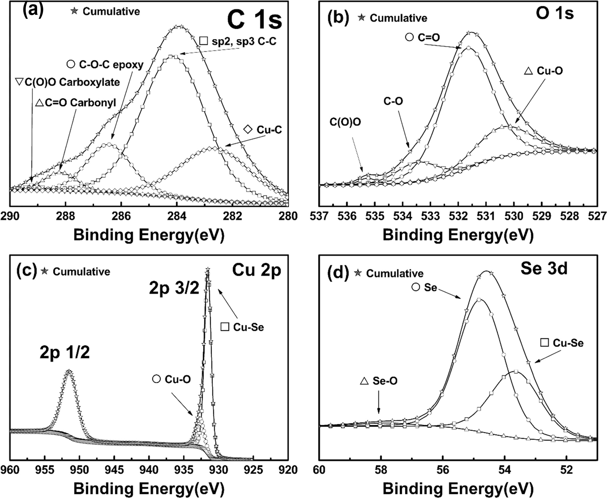
To support the above characterization, XPS was done on the
rGO/Cu3Se2 sample [38]. Fig. 5 shows the XPS spectra of
(a) C 1s, (b) O 1s, (c) Cu 2p, and (d) Se 3d from the
rGO/Cu3Se2 sample. Fig. 5(a) suggests that the
rGO was well reduced by the pulsed electrodeposition process. C-C strongly
remained at 284 eV. The peak value at 284 eV indicated C-C bonds relevant with
sp2 and sp3. There were slightly low residues for the C-O, C=O, O=C-O peaks.
This indicated that the reduction of GO was successful during
electrodeposition. It also corresponded well to the results obtained via Raman
spectroscopy. The broad peak around 283 eV was related to the metallic C [39],
and as Cu was adsorbed onto the rGO, that peak proved the existence of copper
clusters. The relatively small peaks at 286.5 eV, 287.8 eV, and 289.1 eV
corresponded to the results from the D/G ratio Raman spectroscopy, and
indicated the extinction of oxygen containing groups [38]. From the
deconvoluted XPS peak areas, the C/O ratio was calculated to be 8.944. This
indicated an adequate reduction of rGO on the FTO. This result corresponded to
the results from the Raman spectroscopy.
Morphology-dependent
device performance
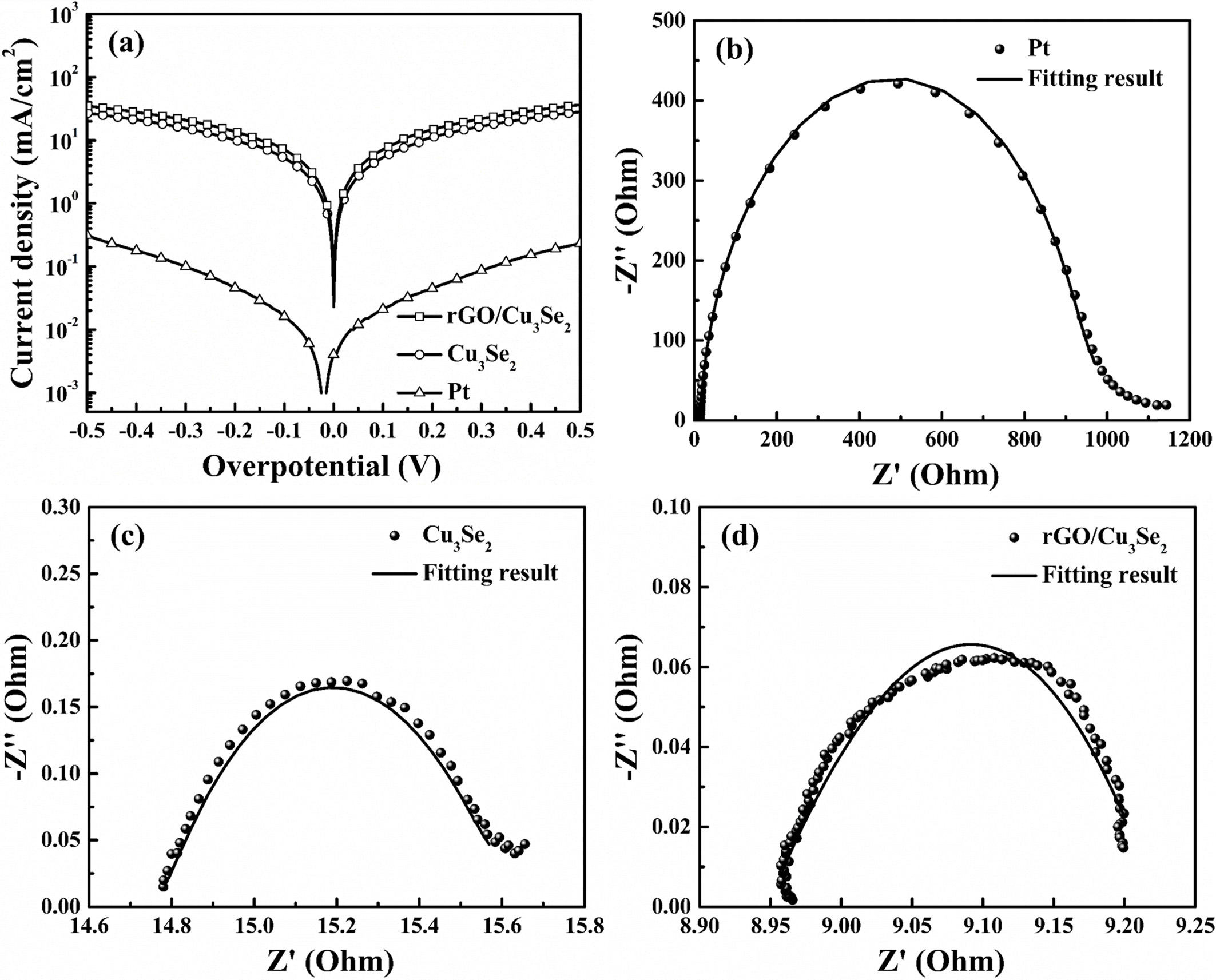
The electrochemical activity of the prepared CEs was
analyzed by Tafel analysis EIS. Fig 6(a) shows the Tafel polarization curves of
the Pt, Cu3Se2 and rGO/Cu3Se2 CEs.
Among these CEs, rGO/Cu3Se2 exhibited the highest
limiting current density (Jlim). The porous structure of the Cu3Se2
grown on rGO provided more electrocatalytic active sites, which lead the
superior mass transfer. Fig. 6(b-d) show the Nyquist plots of different
symmetrical cells and the fitting parameters are listed in Table 3, where RS
the series resistance and Rct is the charge transfer resistance
between the CE and electrolyte. The Rct values of Pt, Cu3Se2
and rGO/Cu3Se2 CEs were 844.9, 1.15 and
0.292 Ω, respectively. This result shows the rGO/Cu3Se2
CE has superior charge transfer kinetics which can affect in FF.
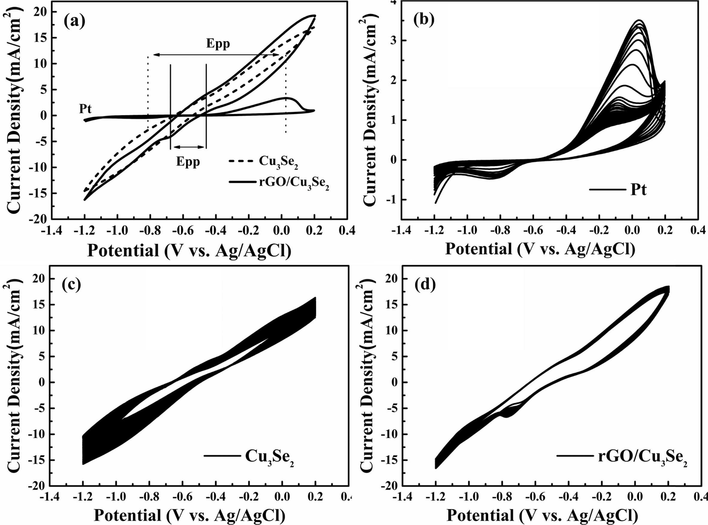
Cyclic voltammetry (CV) was performed to evaluate the
electrocatalytic activity and electrochemical stability. The oxidation
and reduction peak current and peak-to-peak
potential difference (Epp) are simple and powerful tool for
estimate the electrocatalytic activity [40, 41]. Both Cu3Se2
and rGO/Cu3Se2 electrodes with high electrocatalytic
activity showed the lower Epp value than Pt as shown in Fig. 7(a). Meanwhile
the oxidation and reduction peak positions of Cu3Se2 and
rGO/Cu3Se2 electrodes are very similar, the current
densities of the oxidation and reduction peaks of rGO/Cu3Se2
electrode is greater than that of the unmodified Cu3Se2 electrode.
It shows that the Cu3Se2, which grown on rGO, has a
higher surface area due to the porous morphology as observed in SEM. Fig.
7(b-d) show the CV curves of different CEs for 50 cycles. Pt CE has very low
current density owing to their poor electrocatalytic activity and
stability. Cu3Se2 CE has a higher current compared
to Pt but shows apparent current decay which means low
stability. rGO/Cu3Se2 CE has an excellent electrochemical
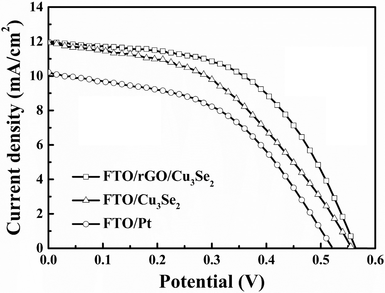
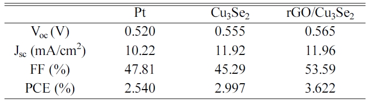
stability in polysulfide electrolyte. Fig. 8 and Table 4 show the J-V curves
and parameters of the QDSSCs with different CEs. QDSSC with rGO/Cu3Se2
CE has the significantly improved FF of 53.59% and PCE of 3.622% compared to Cu3Se2
CE.
|
Fig. 1 XRD results of FTO/Cu3Se2, FTO/rGO/Cu3Se2 and FTO. |
|
Fig. 2 SEM images of electrode surface, (a) FTO/Pt, (b) FTO/rGO, (c) FTO/Cu3Se2 (d) FTO/rGO/Cu3Se2 and (e-g) are cross section of (bd) respectively. |
|
Fig. 3 (a-c) TEM and HRTEM images of Cu3Se2, (d) EDAX objective area, (e, f) Cu and Se elemental mapping in scan area, (g) SAED pattern of sample and (h) FFT from (c). |
|
Fig. 4 Raman spectra of (a) GO, (b) rGO, (c) rGO/Cu3Se2. |
|
Fig. 5 XPS spectra of (a) C 1s, (b) O 1s, (c) Cu 2p and (d) Se 3d from FTO/ rGO/Cu3Se2. |
|
Fig. 6 (a) Tafel polarization curves from symmetrical cells of Pt, Cu3Se2 and rGO/Cu3Se2. Nyquist plots of (b) Pt, (c) Cu3Se2 and (d) rGO/Cu3Se2. |
|
Fig. 7 (a) Cyclic voltammetry curves of CEs. Cycling stability tests for 50 cycles of (a) Pt, (b) Cu3Se2 and (c) rGO/Cu3Se2. |
|
Fig. 8 J-V curves of Pt, Cu3Se2 and rGO/Cu3Se2 electrodes. |
An rGO/Cu3Se2 layered structure was
successfully synthesized onto an FTO substrate through the facile
electrodeposition process. A GO solution composed of Cu-EDTA provided a uniform
rGO film on the FTO substrate. The rGO layer provided active sites for Cu3Se2
growth and also prevented direct contact of the electrolyte with the FTO
substrate, which suppressed recombination. Pulsed electrodeposition resulted in
the stoichiometric formation of Cu3Se2 on rGO-modified
FTO. The deposition of Cu3Se2 on rGO modified FTO
achieved stability under ambient air conditions and a much more porous
structure than the direct formation of Cu3Se2 on FTO. A
strong dependence between the morphology and mass transfer of electrolytes was
observed. The porous structure induced the rGO layer to Cu3Se2
and led to the enhanced performance of the QDSSC from the increased FF and Jlim.
This work was supported by the 2019 Yeungnam University
Research Grant. This study was also supported by
the “Human Resources Program in Energy Technology” of
the Korea Institute of Energy Technology Evaluation and
Planning (KETEP), supported by the Ministry of Trade, Industry & Energy,
Republic of Korea (No. 20174030201760).
- 1. M.C. Beard, J.M. Luther, O.E. Semonin and A.J. Nozik, Acc. Chem. Res. 46[6] (2013) 1252-1260.
-

- 2. D.M. Chapin, C.S. Fuller and G.L. Pearson, J. Appl. Phys. 25[5] (1954) 676-677.
-
- 3. S. Kumar, M. Nehra, A. Deep, D. Kedia, N. Dilbaghi and K.-H. Kim, Renew. Sustain. Energy Rev. 73 (2017) 821-839.
-
- 4. P.V. Kamat, J. Phys. Chem. C. 112[48] (2008) 18737-18753.
-
- 5. F. Huang, J. Hou, H. Wang, H. Tang, Z. Liu, L. Zhang, Q. Zhang, S. Peng, J. Liu, and G. Cao, Nano Energy. 32 (2017) 433-440.
-
- 6. J. Tian, R. Gao, Q. Zhang, S. Zhang, Y. Li, J. Lan, X. Qu, and G. Cao, J. Phys. Chem. C. 116[35] (2012) 18655-18662.
-
- 7. F. Huang, J. Hou, Q. Zhang, Y. Wang, R. Massé, S. Peng, H. Wang, J. Liu, and G. Cao, Nano Energy. 26 (2016) 114-122.
-
- 8. I. Rauf and P. Rezai, Renew. Sustain. Energy Rev. 73 (2017) 408-422.
-
- 9. P.N. Kumar, A. Kolay, S.K. Kumar, P. Patra, A. Aphale, A.K. Srivastava and M. Deepa, ACS Appl. Mater. Interfaces. 8[41] (2016) 27688-27700.
-
- 10. B. Zhang, H. Yuan, X. Zhang, D. Huang, S. Li, M. Wang and Y. Shen, ACS Appl. Mater. Interfaces. 6[23] (2014) 20913-20918.
-
- 11. Y.-L Lee and C.-H. Chang, J. Power Sources. 185[1] (2008) 584-588.
-
- 12. H.K. Jun, M.A. Careem and A.K Arof, Int. J. Photoenergy. 2013 (2013) 1-10.
-
- 13. H.M. Choi, I.A. Ji and J.H. Bang, ACS Appl. Mater. Interfaces. 6[4] (2014) 2335-2343.
-
- 14. V.T. Chebrolu and H.-J. Kim, J. Mater. Chem. C. 7[17] (2019) 4911-4933.
-
- 15. Y. Zhu, S. Murali, W. Cai, X. Li, J.W. Suk, J.R. Potts and R.S. Ruoff, Adv. Mater. 22[35] (2010) 3906-3924.
-
- 16. L. Wang, J. Feng, Y. Tong and J. Liang, Int. J. Hydrog. Energy. 44[1] (2019) 128-135.
-
- 17. J. Ma, W. Shen and F. Yu, J. Power Sources. 351 (2017) 58-66.
-
- 18. S. Li, H. Min, F. Xu, L. Tong, J. Chen, C. Zhu and L. Sun, RSC Adv. 6[41] (2016) 34546-34552.
-
- 19. B. Yuan, Q. Gao, X. Zhang, L. Duan, L. Chen, Z. Mao, X. Li and W. Lü, Electrochim. Acta. 277 (2018) 50-58.
-
- 20. C.L.P. Pavithra, B.V. Sarada, K.V. Rajulapati, T.N. Rao and G. Sundararajan, Sci. Rep. 4[1] (2015) 4049.
-
- 21. A. Moysiadou, R. Koutsikou and M. Bouroushian, Mater. Lett. 139 (2015) 112-115.
-
- 22. B.B. Jin, Y.F. Wang, X.Q. Wang, and J.H. Zeng, Appl. Surf. Sci. 369 (2016) 436-442.
-
- 23. Y.-H. Lee, Y.-H. Yun, VHV. Quy, S.-H. Kang, H.S. Kim, E. Vijayakumar and K.-S. Ahn, Electrochim. Acta. 296 (2019) 364-371.
-
- 24. N.I. Kovtyukhova, P.J. Ollivier, B.R. Martin, T.E. Mallouk, S.A. Chizhik, E.V. Buzaneva, and A.D. Gorchinskiy, Chem. Mater. 11[3] (1999) 771-778.
-
- 25. Y. Mai, M. Zhou, H. Ling, F. Chen, W. Lian, and X. Jie, Surf. Sci. 433 (2018) 232-239.
-
- 26. V. Gonzalez-Pedro, X. Xu, I. Mora-Ser and J. Bisquert, ACS Nano. 4[10] (2010) 5783-5790.
-
- 27. H.J. Lee, M. Wang, P. Chen, D.R. Gamelin, S.M. Zakeeruddin, M. Grátzel, and M.K. Nazeeruddin, Nano Lett. 9[12] (2009) 4221-4227.
-
- 28. J. Yu, W. Wang, Z. Pan, J. Du, Z. Ren, W. Xuea and X. Zhong, J. Mater. Chem. A. 5[27] (2017) 14124-14133.
-
- 29. S. Pei and H.-M. Cheng, Carbon. 50[9] (2012) 3210-3228.
-
- 30. L. Li, J. Gong and W. Zhu, IOP Conf Ser Earth Environ Sci. 59[1] (2017) 012060.
-
- 31. D. Lippkow and H.H. Strehblow, Electrochim. Acta. 43[14-15] (1998) 2131-2140.
-
- 32. J. Sourice, A. Quinsac, Y. Leconte, O. Sublemontier, W. Porcher, C. Haon, A. Bordes, E.D. Vito, A. Boulineau, S.J. Larbi, N. Herlin-Boime, and C. Reynaud, ACS Appl. Mater. Interfaces. 7[12] (2015) 6637-6644.
-
- 33. A. Wang, W. Yu, Y. Fang, Y. Song, D. Jia, L. Long, M.P. Cifuentes, M.G. Humphrey and C. Zhang, Carbon. 89 (2015) 130-141.
-
- 34. S.H. Huh and S. Mikhailov, in “Physics and Applications of Graphene – Experiments” (IntechOpen, 2011) p. 73.
-
- 35. L. Zhou, X. Yang, B. Yang, X. Zuo, G. Li, A. Feng, H. Tang, H. Zhang, M. Wu, Y. Ma, S. Jin, Z. Sun and X. Chen, J. Power Sources. 272 (2014) 639-646.
-
- 36. A. Wei, L. Xiong, L. Sun, Y. Liu, W. Li, W. Lai, X. Liu, L. Wang, W. Huang and X. Dong, Mater. Res. 48[8] (2013) 2855-2860.
-
- 37. M.A. Pimenta, G. Dresselhaus, M.S. Dresselhaus, L.G. Cancado, A. Jorio and R. Saito, Phys. Chem. Chem. Phys. 9[11] (2007) 1276-1290.
-
- 38. A.G. Marrani, R. Zanoni, R. Schrebler, and E.A. Dalchiele, J. Phys. Chem. C. 121[10] (2017) 5675-5683.
-
- 39. N. Dukstiene, L. Tatariskinaite, M. Andrulevicius, Mater Sci-Poland. 28[1] (2010) 93.
- 40. R. Riaz, M. Ali, I.A. Sahito, A.A. Arbab, T. Maiyalagan, A.S. Anjum, M.J. Ko, S.H. Jeong, Appl. Sur. Sci. 480 (2019) 1035-1046.
-
- 41. R. Riaz, M. Ali, H. Anwer, M.J. Ko, S.H. Jeong, J. Colloid Interface Sci. 557 (2019) 174-184.
-
 This Article
-
2020; 21(S1): 33-40
Published on May 31, 2020
- 10.36410/jcpr.2020.21.S1.s33
- Received on Dec 19, 2019
- Revised on Mar 31, 2020
- Accepted on Apr 14, 2020
Services
- Abstract
introduction
experimental section
results and discussion
conclusion
- Acknowledgements
- References
- Full Text PDF
Shared
Correspondence to
- Kwang-Soon Ahn
-
School of Chemical Engineering, Yeungnam University, Gyeongsan 712-749, Republic of Korea
Tel : +82-53-810-2524
Fax: +82-53-810-4631 - E-mail: kstheory@ynu.ac.kr
Clean-Energy Research Institute(CRI), Hanyang University, 222, Wangsimni-ro, Seongdong-gu, Seoul, 04763, Korea
E-mail: jcpr@hanyang.ac.kr