


- Characterization and synthesis of MnZn ferrite nanoparticles synthesized by thermal decomposition
JinAh Hwanga,b, Byeong-Kwon Jub and MyoungPyo Chuna,*
aElectronic Convergence Materials Division, Korea Institute of Ceramic Engineering and Technology, Jinju-si, Gyeongsangnam-do 660-031, Korea
bDisplay and Nanosystem Laboratory, School of Electrical Engineering, Korea University, Seoul 13701, Korea
MnxZn1-xFe2O4
(x = 0.5, 0.6, 0.7) ferrite nanoparticles were synthesized by a thermal
decomposition method. The synthesized particles were identified as pure spinel
ferrite structures by x-ray diffraction analysis and they were calculated to be
15-20 nm in diameter by the Scherrer equation, depending on the composition.
Ferrite nanoparticles are spherical in shape with a slight agglomeration in the
FE-SEM image, and the particle size is about 20 nm, which was consistent with
the value obtained by the Scherrer equation. The lattice parameters of ferrite
nanoparticles monotonously decreased from 8.358 Å to 8.389 Å as the
manganese concentration increased from 0.5 to 0.7. As the manganese content
increases from x = 0.5 to 0.7, the saturation magnetization value increases
from 76 emu/g to 63 emu/g. MnxZn1-xFe2O4
toroidal samples were prepared by sintering ferrite nanoparticles at 1,250 oC
and exhibited faceted grain morphology in FE-SEM images with a grain size of
about 3 um regardless of manganese content. The cutoff frequency of the ferrite
toroidal sample was estimated to be about 3MHz from the broad maximum point in
the plot of imaginary magnetic permeability (μ”) vs. frequencies, which
seems to be associated with domain wall resonance.
Keywords: Nanoparticles, MnZn ferrite, Superparamagnetic
MnZn ferrites have attracted much
attention due to their high permeability and high electrical resistivity [1-4]
and have been used as core materials for choke coils, magnetic amplifiers,
power transformers, solar inverters, new energy vehicles DC/DC converters, wireless batteries Chargers, motor stators and many
other electronic, automotive and communications equipment today [5-10].
Apart from these applications, MnZn
ferrite nanoparticles are also
attractive to biomedical medicine as a result of suitable Curie temperature,
magnetic crystal anisotropy, moderate
saturation magnetization and superparamagnetic behavior at room temperature [11]. They can be used for
magnetic resonance imaging (MRI), hyperthermia, modification, detection,
isolation and study of cells [12], for
isolation of biologically active compounds [13]. If the size of the magnetic particles is smaller than the
critical size for the formation of multiple domains, the particles exist in a single domain state and avoid
domain wall resonance, which is called superparamagnetic state.
The magnetic properties of
nanoparticles can be influenced by the method of synthesis, particle size,
cation distribution and composition. Ferrite particles [14, 15] produced by the
solid phase reaction between constituent oxides or carbonates have many
problems, such as large and non-uniform
particle size and induced impurities, which limits the improvement of the
products [16, 17]. To overcome these
difficulties and meet the requirements for new applications, some wet chemical
processes such as coprecipitation [18], hydrothermal techniques [28], sol-gel
automatic combustion [29], and thermal decomposition of salts [30-34], citrate
precursors [32], and self-propagating high temperature synthesis (SHS) [33]
have been considered for the production
of ferrite nanoparticles with excellent magnetic properties.
In this study, MnxZn1-xFe2O4
(x = 0.5, 0.6, 0.7) nano-
particles were synthesized by a thermal decomposition method in order to
obtain ultra-fine nanoparticles with uniform particle size. Their magnetic
properties such as the saturation magnetization and magnetic permeability were investigated with VSM (Vibrating Sample
Magneto- meter) and impedance analyzer along with their particle morphologies.
In particular, the dependence of the saturation
magnetization on the Mn content was described with the number of the paired
electron and the unpaired electron.
MnxZn1-xFe2O4
(x = 0.5, 0.6, 0.7) nano-particles were synthesized by a thermal
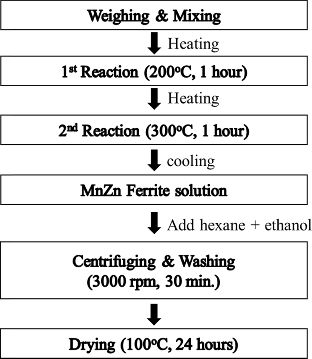
decomposition method as shown in Fig. 1. Raw materials are Manganese(II)
acetylacetonate (97%), Zinc acetylacetonate hydrate (95%), Iron(III) acetylacetonate (97%). Oleic acid (90%) and Oleylamine (70%) were used as a surfactant, 1, 2-Hexadecandediol
(90%) as a reducing agent, and Benzyl
ether (98%) as a solvent. Mn, Zn and Fe-acetylacetonate precursors were
weighed, respectively according to the chemical form of MnxZn1-xFe2O4
(x = 0.5, 0.6, 0.7) and poured into a 500 ml three neck flask that
was filled with a mixed solution of 6mmol oleic acid, 6 mmol oleylamine,
1,2-hexadecandediol (HDD), and 20 ml benzyl ether. The precursor solution was
heated to 200 oC for 1 h, then further heated to 300 oC
and kept there for 1 h, whose process was carried out in N2
atmosphere with refluxing using cooling water. The solution that finished the
reaction was cooled down to room temperature, centrifuged for 30
min at a speed of 4000 rpm and washed repeatedly with hexane and ethanol in order to separate organic remains from the ferrite particles. Hexane was used to
dissolve fat acid such as oleic acid and oleylamine. Finally, MnxZn1-xFe2O4
(x = 0.5, 0.6, 0.7) nanoparticles was collected and dried at 100 oC
for 24 h.
Toroidal samples of MnZn ferrites
were fabricated by the uniaxial pressing. The ferrite powder was mixed with a PVA (Polyvinyl alcohol, 5 wt.%) binder
solution, which was poured into a toroidal
shaped mold and applied with a pressure of 1 ton/cm2 to make green
toroidal samples. The green toroidal samples were burn-out at 650 oC
for 30 min in air and then sintered at 1,250 oC for 2 h under
the nitrogen gas ambience.
Phase purity of MnZn ferrites
nanoparticles was investigated with X-ray diffractometer (XRD: D/max 2200 V/PC,
Rigaku Co., Japan). Microstructures of sintered toroidal ferrite samples were
observed with Scanning Electron Microscope (SEM,
JSM 6700F, Jeol, Japan). Magnetic
permeability (m', m¡È) was
measured from 1MHz to 1GHz with Impedance
analyzer (E4991A). Saturation magnetization of ferrite particles was
measured with VSM (Vibrating Sample
Magnetometer).
|
Fig. 1 Experimental procedure for synthesizing MnxZn1-xFe2O4 (x=0.5, 0.6, 0.7) ferrite nanoparticles. |
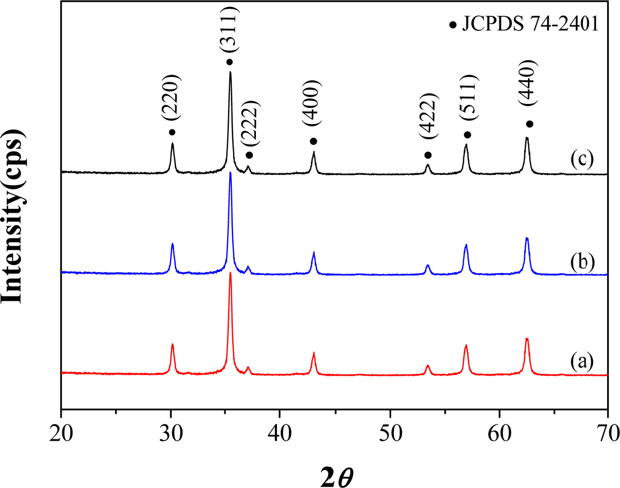
Fig. 2(a)-(c) shows X-ray diffraction
patterns of MnxZn1-xFe2O4 (x
= 0.5, 0.6, 0.7) nanoparticles, which represents a pure spinel structure (JCPDS
74-2401) for all three ferrites without any second phases regardless of
composition.
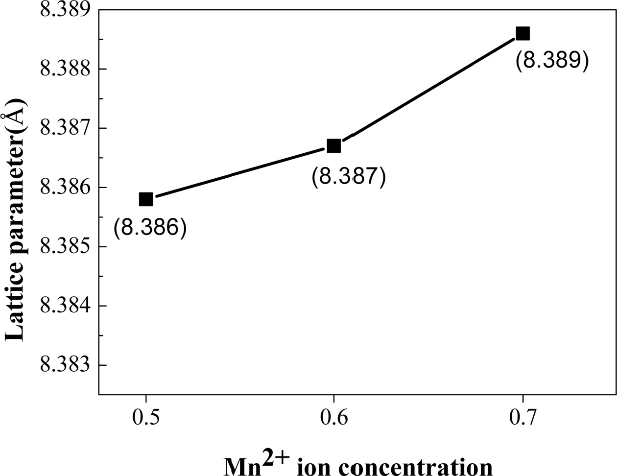
Fig. 3 shows the dependence of the
lattice parameters of the ferrite nanoparticles on the Mn concentration, which
was calculated by the following equation.

The lattice parameters of MnxZn1-xFe2O4
nanoparticles increase continuously and slightly
from 8.386 Å to 8.389 Å as Zn concentration increases from x = 0.5
to 0.7 as shown in Fig. 3, which is reasonable considering that the ionic
radius of Mn+2 (0.83 Å) is larger than that of Zn+2 (0.74
Å). In addition, the incorporated Mn+2 ions can be thought to occupy the Zn sites well according to not only Vegard¡¯s law [19] but also the fact
that both Mn and Zn ions occupy A-sites because MnZn ferrite has normal spinel
structure [20].
Spinel ferrite has a chemical form of
(A)[B2]O4, which is described as a cubic closed-pack of
oxygen ions [21-23]. The round and the
square brackets represent the tetrahedral interstitial A site and the larger
octahedral interstitial B site, respectively.
Zinc ferrite is called a normal spinel structure of the form (Zn)[Fe2]
O4, where Zn2+ ions occupy the tetrahedral sites
and Fe3+ ions occupy the
octahedral sites [24]. It was also reported that Mn-ferrite, (Mn)[Fe2] O4,
the normal spinel structure likewise Zn-ferrite [25].
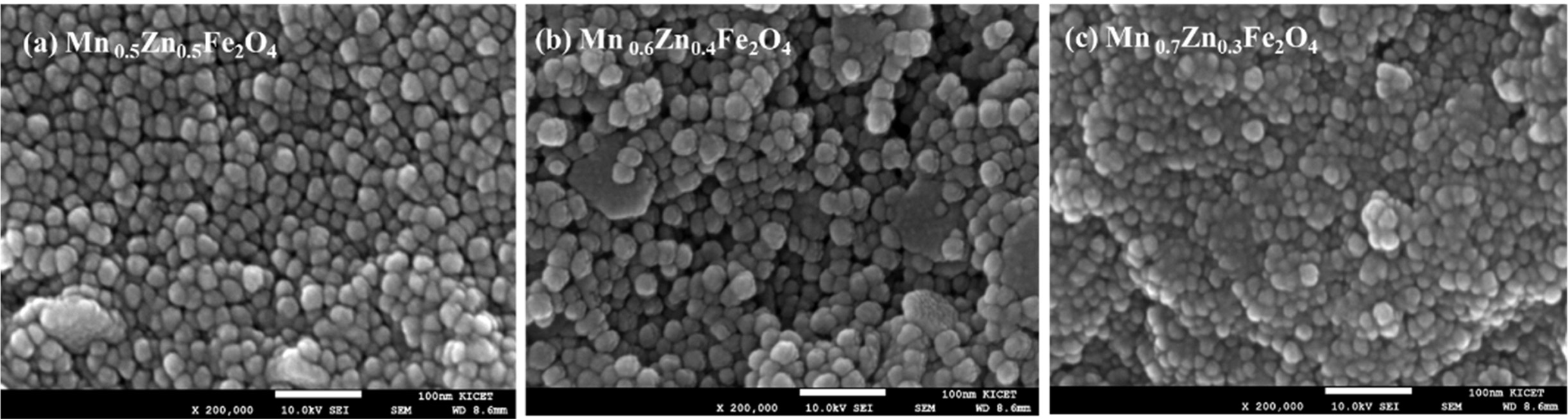
Fig. 4(a-c) shows the microstructures
of MnxZn1-xFe2O4 (x
= 0.5, 0.6, 0.7) nanoparticles synthesized by the thermal decomposition. Most
particles, regardless of Mn
concentration, are round shaped and almost identical in size with a diameter of about 20 to 30 nm, which is in
good agreement with the crystal size of 24.6 nm, calculated by Scherer's
equation [31] using a (311) diffraction peak.
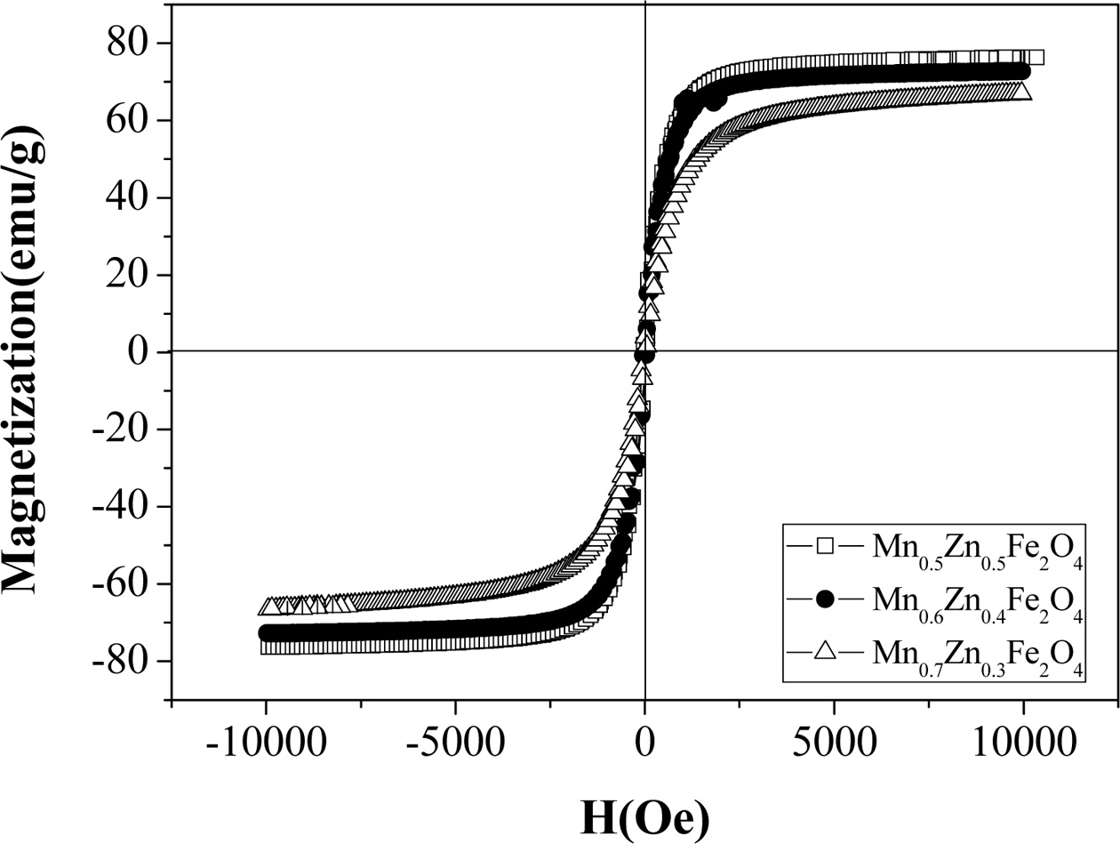
Fig. 5 shows the hysteresis curve of
MnxZn1-xFe2O4 (x = 0.5,
0.6, 0.7) nanoparticles. As the Mn ion concen- tration increases from x = 0.5 to
0.7, the saturation magnetization decreases from 76 to 53 emu/g. These
magnetization values are thought to be high, which can be derived from a
superparamagnetic behavior due to their small particles [32].
The spinel ferrite is cubic and is
represented as the general formula AB2O4,
in which there exist the octahedral and
tetrahedral interstitial sites occupied by transition metal cations. Spinel
ferrites are classified as a normal spinel or an inverse spinel depending on
where cations occupy octahedral sites or tetrahedral sites and can be
represented as follows:
Me2+[Fe23+]O4 normal spinel
Fe3+[Me2+Fe3+]O4 inverse spinel
Where the ions on the octahedral
sites are enclosed in brackets. Normal spinels are formed when Me2+
= Zn or Cd, and inverse spinels when Me2+ = Ni, Co, Fe, Mn, or Cu.
The ferric ion can occupy either tetrahedral or octahedral sites, depending on
what other cations are present. The saturation magnetization of ferrite is
equal to the difference in sublattice magnetization associated with octahedral
and tetrahedral sites. ZnFe2O4 is a normal spinel, but
MnFe2O4 is an inverse spinel. These two compounds form a
solid solution MnxZn1-xFe2O4
and can be expressed as Zn1-x2+Fex3+[Mnx 2+Fe2-x3+]O4,
taking into account the site preference of cations. As the Mn content increases
at the octahedral site, the number of Fe3+ ions at the octahedral
site decreases, while the number of
Fe3+ ions and Zn2+ ions at the tetrahedral site increases and decreases, respectively. Zn2+
ions have no unpaired electrons, but Mn2+ and Fe3+ ions
each have 5 unpaired electrons. The number of unpaired electrons at the
octahedral site is 5x + 5(2 - x) = 10, but the number of unpaired electrons at the tetrahedral site is 0 * (1 - x) + 5 x = 5x.
Therefore, the total unpaired electrons are 10 - 5x because the spin
directions of the unpaired electrons between the octahedral and the tetrahedral
sites are opposite to each other.
As a result, as the Mn content
increases, the saturation
magnetization is reduced due to the decreased anti- ferromagnetic coupling, which is well
consistent with our results of the saturation magnetization.
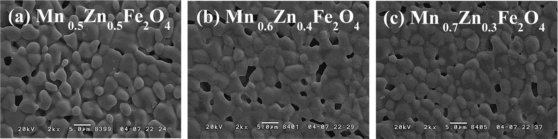
Fig. 6(a)-(c) is FE-SEM images of MnxZn1-xFe2O4
(x = 0.5, 0.6, 0.7) samples
sintered at 1,250 oC in N2 atmosphere. The grain size is about 3-5 um, but slightly decreased as the Mn content increased. It can be
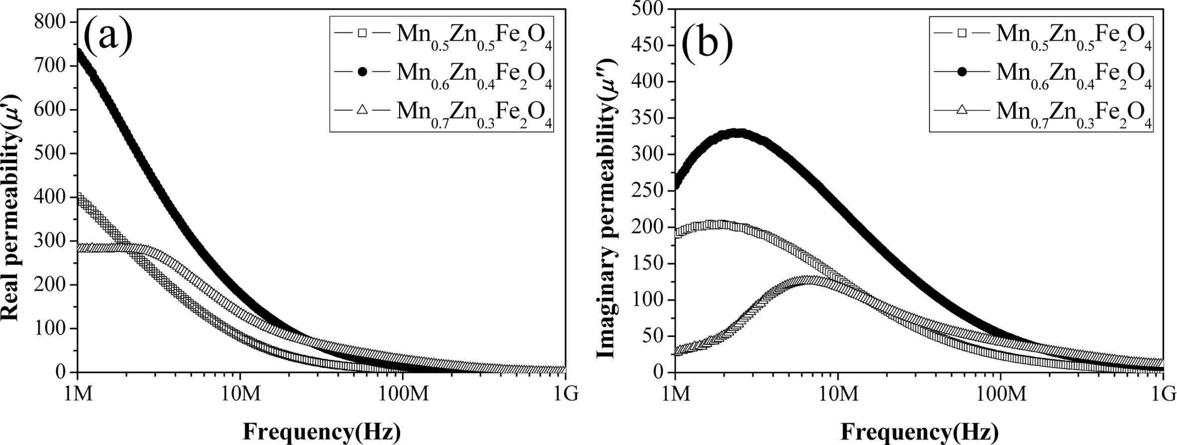
seen that a few large pores presumably due to condensation under observation. Fig. 7(a)-(b) shows the real and imaginary parts of
magnetic permeability of MnxZn1-xFe2O4
(x = 0.5, 0.6, 0.7) toroidal samples in the frequency range from 1 MHz to 1 GHz. The Mn0.6Zn0.4Fe2O4 sample
exhibits the highest value of about 740 at the real permeability (μ')
at 1 MHz of the three composition samples, and its cut-off frequency was 2.36
MHz, which was obtained from the peak point of the imaginary permeability (μ").
The Mn0.7Zn0.3Fe2O4 sample shows
the lowest value of about 285 at the actual
permeability (μ') at 1 MHz of the three composition samples,
but the highest value at the actual permeability (μ') above 30 MHz, and the cut off frequency is 6.95 MHz.
Since the initial permeability is
proportional to the square of the saturation magnetization and reversely
proportional to the anisotropy constant and magneto- striction [34]. The
observed increase in the initial permeability of the Mn0.6Zn0.4Fe2O4
sample is believed to be due to an increase in saturation magnetization, as
well as a decrease in anisotropy and magnetostriction constants. The Mn0.7Zn0.3Fe2O4
sample exhibits the largest value at a real permeability (μ') of 30 MHz
and above, and can generally be described by two types of magnetization
mechanisms: spin rotation and domain wall motion.
|
Fig. 2 X-ray diffraction patterns of MnxZn1-xFe2O4 (x = 0.5, 0.6, 0.7) nanoparticles of the synthesized samples. (a) x = 0.5 (b) x = 0.6, and (c) x = 0.7 |
|
Fig. 3 The dependence of the lattice parameters of the MnxZn1-xFe2O4 (x = 0.5, 0.6, 0.7) ferrite nanoparticles on the Mn concentration. |
|
Fig. 4 FE-SEM image of synthesized MnxZn1-xFe2O4 (x = 0.5, 0.6, 0.7) nanoparticles. (a) x = 0.5 (b) x = 0.6, and (c) x = 0.7. |
|
Fig. 5 Hysteresis curves of MnxZn1-xFe2O4 (x=0.5, 0.6, 0.7) ferrite nanoparticles. |
|
Fig. 6 FE-SEM images of the MnxZn1-xFe2O4 (x = 0.5, 0.6, 0.7) samples sintered at 1,250 oC. (a) x = 0.5 (b) x = 0.6, and (c) x = 0.7. |
|
Fig. 7 Real part (a), and imaginary part (b) of the magnetic permeability of MnxZn1-xFe2O4 (x = 0.5, 0.6, 0.7) toroidal samples in the frequency range from 1 MHz to 1 GHz. |
MnxZn1-xFe2O4
(x = 0.5, 0.6, 0.7) ferrite nanoparticles were well synthesized by
a thermal decomposition method and identified as pure spinel ferrite structures
by x-ray diffraction analysis. The synthesized ferrite nanoparticles were calculated to be 22.9 nm in diameter by the Scherrer equation, which was well consistent
with the particle size of about 25 nm observed from FE-SEM images. The lattice
parameters of ferrite nanoparticles monotonously decreased as the Mn content
increased. The synthesized ferrite nanoparticles showed the superparamagnetic
properties characterized by high saturation magnetization, zero coercivity and
remanence. The saturation magnetization value was 76-66 emu/g depending on the Zn content. Toroidal samples were prepared by sintering ferrite nanoparticles at
1,250 oC in N2 atmosphere, and they exhibited
faceted grain morphology in FE-SEM images with a grain size of about 3-5 ¥ìm.
The real permeability (¥ì') at 1 MHz of the three composition samples,
and its cut-off frequency was 2.36 MHz, which was obtained from the peak point
of the imaginary permeability (¥ì¡±). The cutoff frequency of the
ferrite toroidal sample was about 20 MHz, which seemed to be associated with
domain wall resonance.
- 1. A. Žnidaršič, M. Drofenik, J. Am. Ceram. 65 (1999) 359-365.
-

- 2. M. Gu,G. Liu, W. Wang, Mater. Sci. Eng. B 158 (2009) 35-39.
-
- 3. K. Praveena, H. Chen, H. lin Liu, K. Sadhana, S.R. Murthy, J. Magn. Magn. Mater. 420 (2016) 129-142.
-
- 4. V.T. Zaspalis, V. Tsakaloudi, G. Kogias, EPJ Web Conf. 75 (2014) 3-9.
- 5. G. Kogias, V.T. Zaspalis, Ceram. Int. 42 (2015) 7639-7646.
-
- 6. X. Jiang, S. Chu, Y. Chen, Y. Zhong, Y. Liu, Z. Shao, J. Alloy. Comp. 691 (2017) 206-214.
- 7. P. Hu, H. Yang, D. Pan, H. Wang, J. Tian, S. Zhang, X.Wang, A.A. Volinsky, J. Magn. Magn. Mater. 322 (2010) 173-177.
- 8. D. Stoppels, J. Appl. Phys. 51 (1980) 2789-2794.
- 9. A. Znidarsic, M. Limpel, and M. Drofenik, IEEE Trans- actionson Magnetics 31 (1995) 950-953.
-
- 10. S.F. Wang, Y.J. Chiang, Y.F. Hsu, C.H. Chen, J. Magn. Magn. Mater. 365 (2014) 119-125.
- 11. X. Shen, J. Xiang, F. Song, M. Liu, Appl. Phys. A: Mater. Sci. Process. 99 (2010) 189-195.
-
- 12. I. Šafaˇ rik and M. Šafaˇ rikova, J. Chromatogr. B 722[1-2] (1999) 33-53.
-
- 13. K. Sode, S. Kudo, T. Sakaguchi, N. Nakamura, and T. Matsunaga, Biotechnol. Tech. 7[9] (1993) 688-694.
-
- 14. C.F. Zhang, X.C. Zhong, H.Y. Z.W. Liu, D.C. Zeng, Phys. B 404 (2009) 2327.
-
- 15. M.J.N. Isfahani, M. Myndyk, D. Menzel, A.F.J. Amighian, V. Sepelak, J. Magn. Magn. Mater. 321 (2009) 152.
-
- 16. Z.G. Zheng, X.C. Zhong, Y.H.Zhang, D.C. Zeng, J. Zhao, S.G. Wu, G.W. Huang, L.J. San, J. Univ. Sci. Technol. Beijing 30 (2009) 527.
- 17. A.V. Kadu, S.V. Jagtap, G.N. Chaudhari, Curr. Appl. Phys. 9 (2009) 1246.
-
- 18. D. Varshney, K. Verma, A. Kumar, Mater. Chem. Phys. 131 (2011) 413-419.
-
- 19. J.M. Daniels, A. Rosencwaig, Can. J. Phys. 48 (1970) 381.
-
- 20. J. Smit, H.P.J. Wijn, in “Ferrites’ (Philips Technical Laboratory, 1959) p.369.
- 21. D. Carta, D. Loche, G. Mountjoy, G. Navarra, and A. Corrias, J. Phys. Chem. C 112[40] (2008) 15623-15630.
-
- 22. B. Kaur, M. Arora, A. Shankar, A.K. Srivastava, R.P. Pant, Adv. Mater. Lett. 3[5] (2012) 399.
-
- 23. P.P. Goswami, H.A. Choudhury, S. Chakma, and V.S. Moholkar, Ind. Eng. Chem. Res. 52[50] (2013) 17848-17855.
-
- 24. M.J. Akhtar, M. Nadeem, S. Javaid, and M. Atif, J. Phys.: Condens. Matter, 21[40] (2009), 405303.
-
- 25. H. Farooq, M.R. Ahmad, Y. Jamil, A. Hafeez, Z. Mahmood and T. Mahmood, J. Basic Appl. Sci. 8 (2012) 597-601.
-
- 26. I.Z. Rahman, and T.T Ahmed, J. Magn. Magn. Mater. 290-291 (2005) 1576-1579.
-
- 27. Q. Li, C.W. Kartikowati, S. Horie, T. Ogi, T. Iwaki, and K. Okuyama, Sci. Rep. 7[1] (2017) 9894.
-
- 28. D. Zhang, X. Zhang, X. Ni, J.M. Song, H. Zheng, Chem. Phys. Lett. 426 (2006) 120-123.
-
- 29. P. Hu, H.B. Yang, D.A. Pan, H. Wang, J.J. Tian, S.G. Zhang, X.F. Wang, A.A. Volinsky, J. Magn. Magn. Mater. 322 (2010) 173.
-
- 30. C.-Y. Zhang, X.-Q. Shen, J.-X. Zhou, M.-X. Jing, and K. Cao, J. Solgel Sci. Technol. 42 (2007) 95-100.
-
- 31. S.C. Mojumdar, V.M.S. Verenkar, and L.R. Gonsalves, J. Therm. Anal. Cal. 100 (2010) 789-792.
-
- 32. P.A. Jadhav, R.S. Devan, Y.D. Kolekar, and B.K. Chougule, J. Phys. Chem. Solids 70 (2009) 396-400.
-
- 33. C.C. Agrafiotis, V.T. Zaspalis, J. Magn. Magn. Mater.283 (2004) 364-374.
-
- 34. A. Goldman, in “Handbook of Ferromagnetic Materials” (Kluwer, 1999) p.646.
 This Article
-
2020; 21(S1): 28-32
Published on May 31, 2020
- 10.36410/jcpr.2020.21.S1.s28
- Received on Dec 15, 2019
- Revised on Mar 9, 2020
- Accepted on Mar 16, 2020
Services
Shared
Correspondence to
- MyoungPyo Chun
-
Electronic Convergence Materials Division, Korea Institute of Ceramic Engineering and Technology, Jinju-si, Gyeongsangnam-do 660-031, Korea
Tel : +82-55-792-2680
Fax: +82-55-792-2704 - E-mail: myoungpyo@kicet.re.kr
Clean-Energy Research Institute(CRI), Hanyang University, 222, Wangsimni-ro, Seongdong-gu, Seoul, 04763, Korea
E-mail: jcpr@hanyang.ac.kr