


- Titanium dioxide nanoparticles dispersed in heteroatom-doped carbon nanofibers for ultrafast lithium storage
Ki-Wook Sung and Hyo-Jin Ahn*
Department of Materials Science and Engineering, Seoul National University of Science and Technology, Seoul 01811, Korea
Titanium dioxide (TiO2)
is a promising anode material for lithium-ion batteries (LIBs) owing to its low
price, excellent cycling stability, low operating voltage, and environmentally
friendly nature. However, owing to their poor electrical and ionic diffusion,
TiO2 anodes show low specific capacity and poor high-rate
performance. In this study, in an attempt to improve the electrical and ionic
diffusion properties, we dispersed TiO2 nanoparticles into N- and
P-doped carbon nanofibers (N/P-doped CNF/TiO2) using the
hydrothermal, electrospinning, and carbonization processes. The N/P-doped
CNF/TiO2 electrode showed high specific capacity (311.5 mAh g-1 at 100 mA g-1 after 100 cycles),
outstanding high-rate performance (286 mAh g-1 at 2000 mA g-1), and excellent ultrafast cycling stability (285 mAh
g-1 at 2000 mA g-1 after 500 cycles). The
results showed that dispersing TiO2 nanoparticles into N- and
P-doped CNFs is an efficient approach to improve their electrical conductivity,
shorten their lithium ion diffusion pathways, and stabilize the electrochemical
conditions for ionic diffusion during ultrafast cycling.
Keywords: Lithium-ion batteries, TiO2 nanoparticles, Carbon nanofibers, Heteroatom doping, Synergistic effect, Ultrafast cycling performance
Over the past few years, the rapid depletion of fossil
fuels and ecological concerns such as global warming and environmental
pollution have tremendously increased the demand for
environmentally friendly energy storage devices. Various energy
storage devices such as supercapacitors, fuel cells, and lithium-ion batteries
(LIBs) have gained immense attention as the main power source for electric
vehicles (EVs). Among these energy storage devices, LIBs are widely used as the
main power source for EVs because of their high energy density, long lifespan,
low memory effect, and eco-friendliness [1-5]. However, LIBs suffer from long
charging times. For instance, Tesla Model 3 EV requires a long charging time of
20-30 h at home or 5-6 h at a charging point [5, 6]. To overcome this
limitation of EVs, LIBs with ultrafast charging/discharging, high capacity, and
cycling stability have been developed [5, 7, 8].
As the storage rate of an anode is the limiting factor for
its ultrafast charging, the performance of LIB anodes depends on their
properties. In order to improve the cycling capacity and cycling stability of
LIB anodes (metal, metal oxide, and non-metal), they are composited with carbon
materials (graphite, graphene, and carbon nanofibers) [9-11]. Titanium dioxide
(TiO2) is a widely used anode material owing to its low cost, low
volume expansion, and high cycling stability during the charging/discharging
processes [12-15].
However, the low electrical conductivity and low lithium
ion diffusivity of TiO2 deteriorate the specific capacity and rate
performance of TiO2 LIB anodes [12, 16-18]. These limitations of TiO2
LIB anodes can be overcome by forming composites with
carbon nanofibers (CNFs), which exhibit high electrical conductivity (~100
S cm-1),
high specific surface area (~621 m2 g-1)
, and a one-dimensional network structure [5, 19-21].
Various studies have been carried out to improve the
electrochemical behavior of carbon-based materials through surface modification
by heteroatom doping [22-26]. Heteroatom doping improves the electrical
conductivity and high structural stability of the carbon structure and provides
a large number of active sites through the formation of defect sites by the
carbon-heteroatom bonds [27]. The doped heteroatoms function
as electron-rich or electron-deficient dopants, thus affecting the charge
density around the carbon atoms and generating a large number of surface
functional groups. These functional groups facilitate the absorption of
electrolyte ions on the electrode surface, thus improving the
cycling stability of the electrode [27, 28].
It is well-known that anionic dopants such as N and P
improve the electrical conductivity, faradaic process activity, and
structural stability of carbon-based materials by modifying
the orbital structure of their bonds with carbon [22, 27]. However, it is
challenging to develop metal oxide-carbon nanocomposite structures (obtained
through heteroatom doping) with ultrafast charging/discharging during cycling.
Thus, in this study, we dispersed TiO2
nanoparticles (NPs) in N- and P-doped CNFs to develop LIB anodes
(N/P-doped CNF/TiO2) with ultrafast
charging/discharging. The TiO2 NPs were fabricated using the
hydrothermal method, and the N-/P-doped CNF/TiO2 anodes were
fabricated via electrospinning and calcination.
N/P-doped CNF/TiO2 was fabricated via
hydrothermal synthesis, electrospinning, and
carbonization. First, in order to synthesize the TiO2 NPs, titanium
(IV) isopropoxide (C12H28O4Ti,
97%, Sigma-Aldrich) was dispersed in a solution of deionized (DI) water and ethylenediamine
(C2H8N2, 99.5%, Sigma-Aldrich) under
stirring for 2 h. This solution was transferred to an 80 mL Teflon-lined
stainless-steel autoclave and stirred for 3 h. A hydrothermal reaction was
carried out at 170 °C for 4 h. The samples were then washed five times with DI
water and dried in an oven at 80 °C. In order to synthesize N/P-doped CNF/TiO2,
~15 wt% of the TiO2 NPs and 10 wt% of polyacrylonitrile (PAN, Mw
= 150,000, Sigma-Aldrich, also known as vinyl cyanide) were dispersed in an
N,N-dimethylformamide (DMF, 99.8%, Sigma-Aldrich) solution. For
the electrospinning process, the needle was kept at 23 gauge, and the
distance between the needle and the collector was 15 cm. The feeding rate and
voltage were set at 0.03 mL h-1
and 13 kV, respectively. A relative humidity of less than 15% was maintained in
the electrospinning chamber.
For preparing the P-doped CNFs, stabilized NFs, which were
heated at 200 °C for 2 h in air, were mixed with red P (Mw = 30.97,
Aladdin) in the ratio of 1: 3 and the resulting mixture was calcined at 800 °C
for 2 h. The resulting P-doped CNFs were then used to prepare N/P-doped CNF/
TiO2. For comparison, N-doped CNF/TiO2, bare CNFs, and
bare TiO2 NPs were also prepared.
The morphologies and structures of all the samples were
observed using field-emission scanning electron microscopy
(FESEM, Hitachi S-4800) and transmission electron
microscopy (MULTI/TEM; Tecnai G2, KBSI Gwangju Center). The crystal
structures of the samples were examined using X-ray diffraction (XRD, Rigaku
D/Max 2500V) over the 2θ range of 10-90° with a step size of 0.02°. As the CNF
matrix decomposes over 450°C in an air atmosphere, thermogravimetric (TG,
TGA-50) measurements were carried out over the temperature range of 200-900 °C at
a heating rate of 10 °C min-1
under an air atmosphere to calculate the carbon content within the samples.
Thus, the carbon content of TiO2 NPs, N-doped CNF/TiO2,
and N/P-doped CNF/TiO2 were calculated as 0%, 31%, and 31%. The
chemical bonding states of the samples were determined by X-ray photoelectron
spectroscopy (XPS, ESCALAB 250) using Al Ka X-ray sources.
The porous structures of the samples were examined by obtaining their N2
adsorption/desorption isotherms using the Brunauer-Emmett-Teller (BET) and Barrett-Hoyner-Halenda (BJH) methods.
The electrochemical performances of the samples were
evaluated using coin-type cells (CR2032, Hohsen Corporation) with the prepared
samples as the anode, a lithium metal foil (Honjo Chemical, 99.8%) as the cathode,
a 1.0 M LiPF6 solution in a mixture of ethylene
carbonate-dimethyl carbonate (1:1) as the electrolyte, and a porous
polypropylene membrane (Celgard 2400) used as the separator. To fabricate the
anodes, a slurry was prepared using 70 wt% of the prepared samples, with 20 wt%
of polyvinylidene fluoride as the binder, and 10 wt%
Ketjenblack (Alfa Aesar) as the conducting material, in
N-methyl-2-pyrrolidinone (Sigma-Aldrich). The homogenized slurry was coated on
to a Cu foil (Nippon Foil, 18 mm) and then oven-dried at 100 °C for 12 h. All
the coin-type cells were assembled in a high-purity argon-filled glove box
(< 5 ppm H2O and O2).
Charging/discharging tests were carried out using a battery cycler system
(WonATech Corp., WMPG 3000) over the
potential range of 0.05-3.00 V (vs. Li/Li+) at 25 °C in an incubator.
Cyclic voltammetry (CV) measurements
were carried out on a potentiostat/galvanostat (EcochemieAutolab PGST302N) at
the scan rate of 0.1 mV s-1
over the potential range of 0.05-3.00 V (vs. Li/Li+).
The cycling stability of the samples was evaluated up to 100 cycles at a
current density of 100 mA g-1. The high-rate cycling
performance of the samples was observed for
10 cycles at the current densities of 100, 300, 500, 700, 1,000, and 2,000
mA g-1.
The ultrafast cycling density of the samples was examined for 500 cycles at a current density of 2,000 mA g-1.
Electrochemical impedance spectroscopy (EIS) measurements were carried out using fresh
cells over the frequency range of 105-10-2
Hz by applying an AC signal of 5 mV.
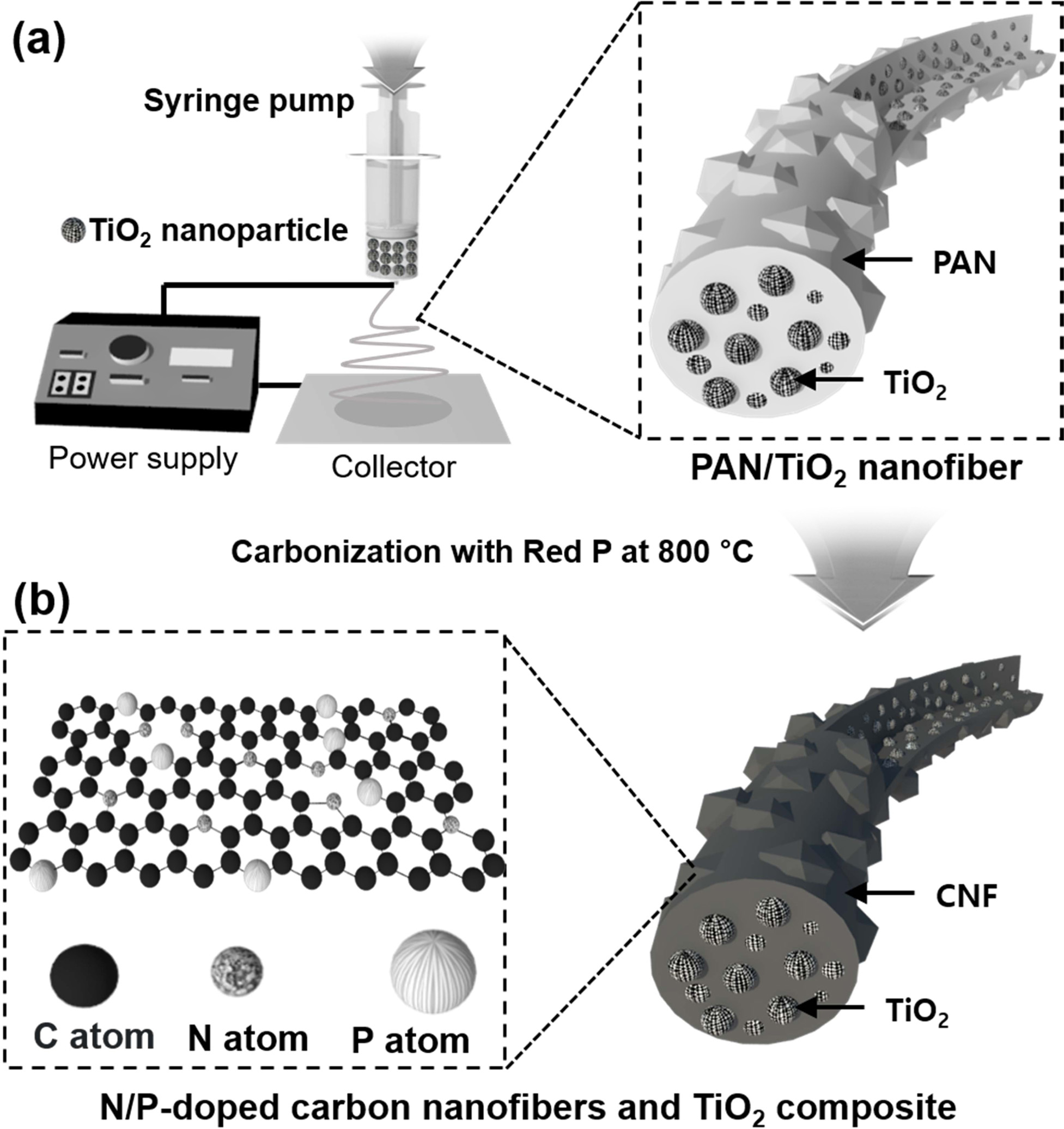
As shown in Fig. 1, the N/P-doped CNF/TiO2
sample was synthesized via electrospinning and carbonization. For the
electrospinning process, the TiO2 NPs prepared using the
hydrothermal process and PAN were stirred in DMF. The as-spun NFs with TiO2
NPs embedded in the PAN NFs were collected as shown in Fig. 1(a). The as-spun
NFs were stabilized, mixed with red P, and carbonized at 800 °C for 2 h in a
nitrogen atmosphere. The red P and N atoms (donated by the PAN NFs) yielded
N/P-doped CNFs (Fig. 1(b)).
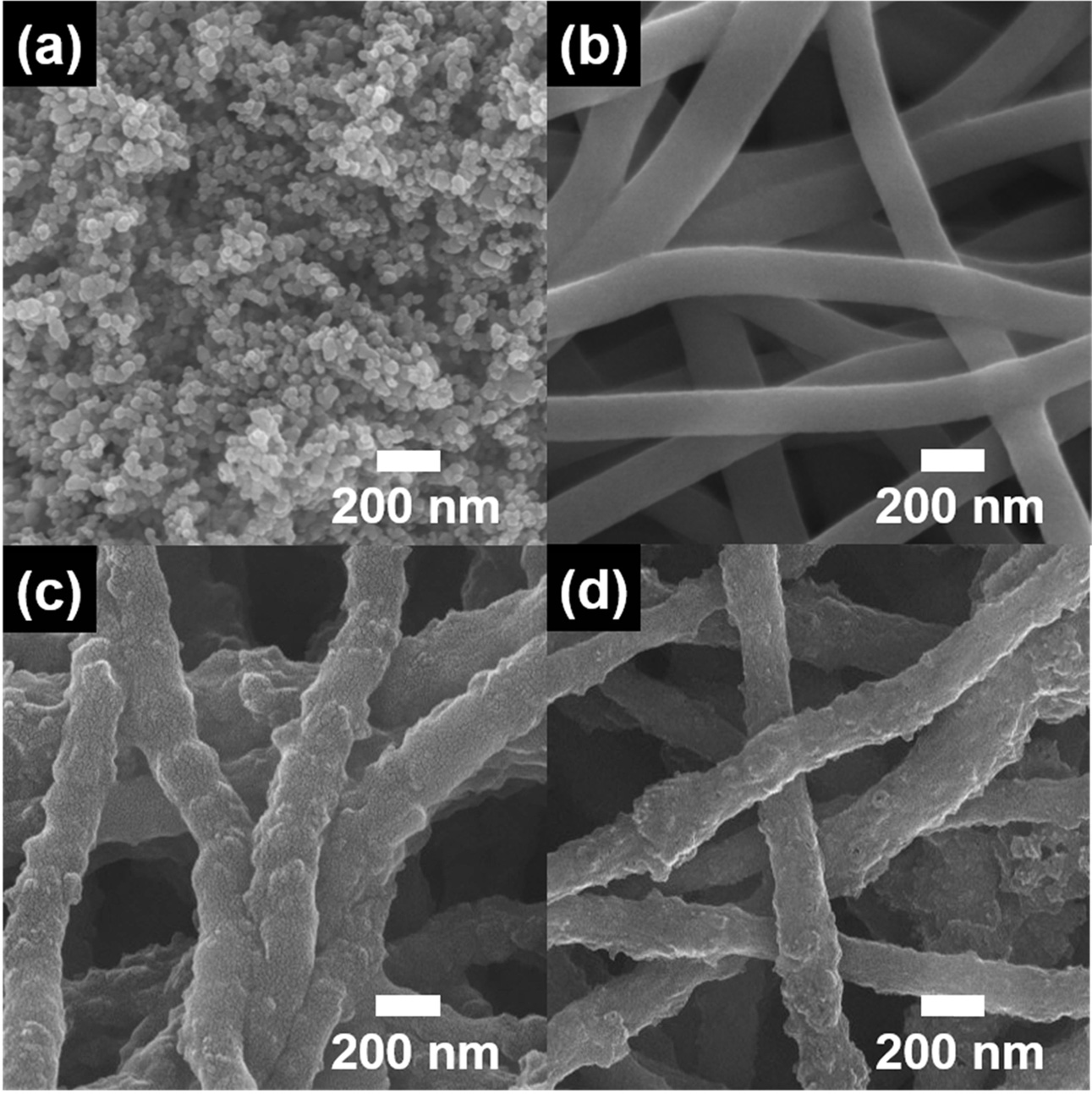
Fig. 2 shows the FESEM images of the TiO2 NP,
bare CNF, N-doped CNF/TiO2, and N/P-doped CNF/TiO2 samples.
The TiO2 NPs were found to be ~37-46 nm in size, while bare CNFs
showed a diameter of ~147-189 nm (Figs. 2(a) and 2(b)). N-doped CNF/TiO2
and N/P-doped CNF/TiO2 (Figs. 2(c) and 2(d)) with the diameters of
~179-220 and ~155-206 nm, respectively, showed bumpy
fiber structures because of the distribution of TiO2
NPs in their CNF matrices. Because of the presence of
one-dimensional NFs, the composites showed an
interconnected network structure, which improved their electron transfer and
lithium-ion diffusion rates, thus improving the LIB performance
[29-32]. In addition, when P was doped onto the surface of the CNFs, the
carbon atoms in the C-C bonds were replaced by P atoms. This is because the
atomic radius of P (1.1 Å) is larger than that of C (0.77 Å). Moreover, P
doping increased the surface roughness of the CNFs through lattice expansion.
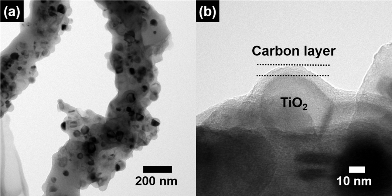
To further examine the structure of the well-dispersed TiO2
NPs in the N/P-doped CNFs, TEM analysis was carried out. Fig. 3 shows the
low-resolution (Fig. 3(a)) and high-resolution (Fig. 3(b)) TEM images of the
N/P-doped CNF/TiO2 composite. The TiO2 NPs were ~37-46 nm
in diameter and were well-dispersed in the CNF matrix (Fig. 3(a)). Fig. 3(b)
shows that the TiO2 NPs were coated with a carbon layer. Thus, the
well-dispersed TiO2 NPs increased the electrical
conductivity of the CNFs, which in turn improved the lithium ion
intercalation/deintercalation kinetics of the composite by reducing the lithium
ion diffusion length.
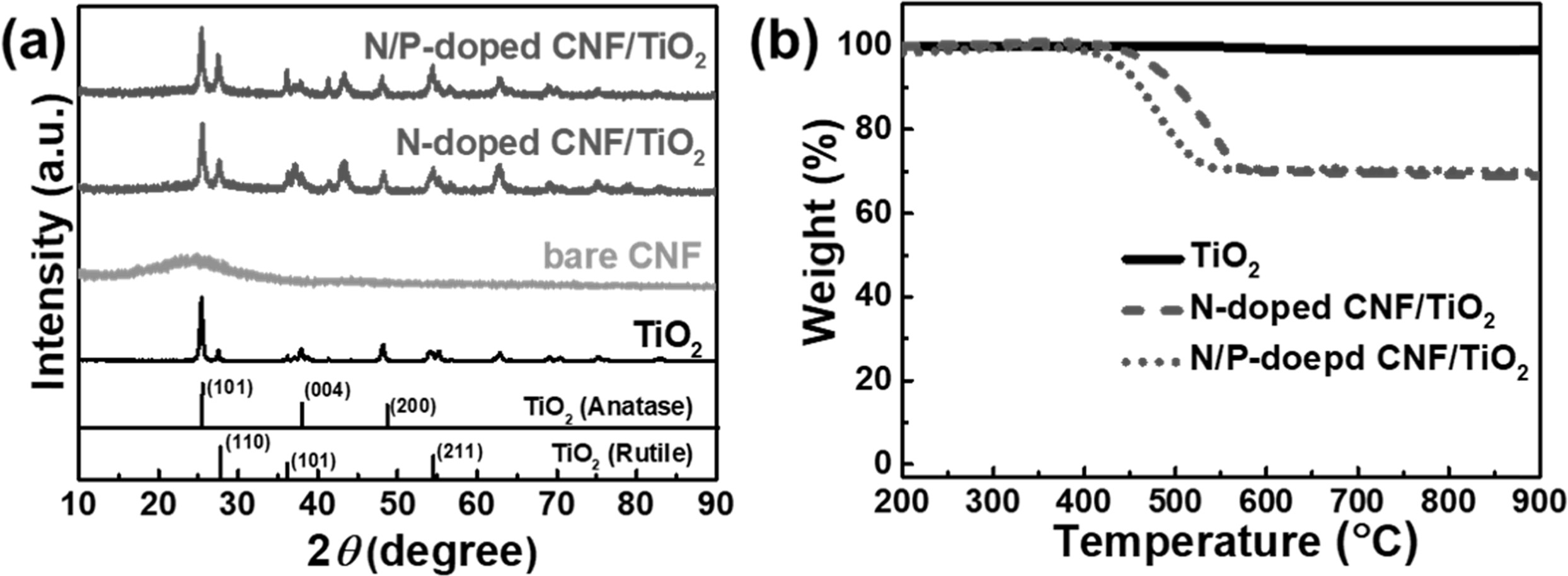
The crystal structures of the TiO2 NP, bare
CNF, N-doped CNF/TiO2, and N/P-doped CNF/TiO2 samples were
analyzed by XRD (Fig. 4(a)). The TiO2 NPs showed
peaks at 2θ = 27.6°, 36.2°, and 54.6° corresponding to the (110), (101), and
(211) planes of the main rutile phase, respectively. The anatase peaks were
observed at 2θ = 25.3°, 37.8°, and 48.1° corresponding to the (101), (004), and
(200) planes, respectively [33]. The bare CNFs exhibited a broad diffraction
peak at 2θ = 25°, corresponding to the (002) plane of graphite [34]. The
N-doped CNF/TiO2 composite showed a broad diffraction peak at 2θ =
25° corresponding to the (002) plane of graphite along with TiO2
diffraction peaks. This indicates that this composite consisted of both the TiO2 and CNF phases. The N/P-doped
CNF/TiO2 composite showed the same diffraction peaks as those shown by the N-doped CNF/TiO2
composite, indicating that P doping
did not affect the crystal structure of the N-doped CNF/TiO2
composite.
TGA were carried out to determine the concentrations
of the TiO2 NP, N-doped CNF/TiO2, and N/P-doped CNF/TiO2
samples. No weight loss was observed for the TiO2 NPs with an
increase in temperature (Fig. 4(b)), indicating that these NPs did not contain
any impurities. The N-doped CNF/TiO2 and N/P-doped CNF/TiO2
composites showed a weight loss of 69% because of the presence of carbon in
them. In addition, as the P doping resulted in the breakage of the CNF bonding
structure, the N/P-doped CNF/TiO2 composite showed initial weight
loss at a temperature lower than that for the N-doped CNF/TiO2 composite.
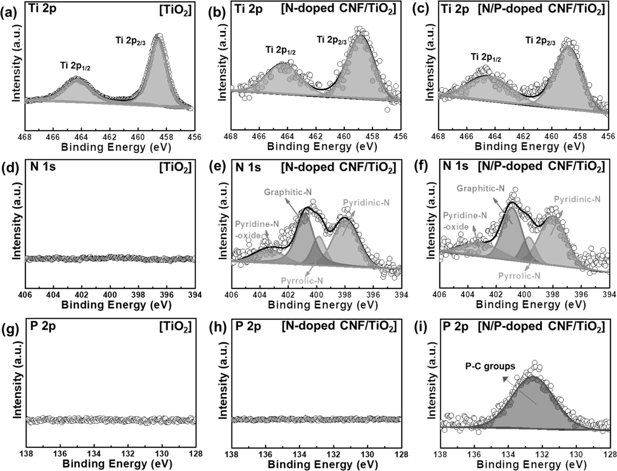
XPS measurements were carried out to investigate the
chemical bonding states of the samples. The Ti 2p XPS profiles (Figs. 4(a-c))
of the samples could be deconvoluted into two peaks at ~464.6 and ~458.9 eV
corresponding to the Ti 2p1/2 and Ti 2p3/2 orbitals,
respectively [35]. The TiO2 NPs did not exhibit N 1s and P 2p peaks
(Figs. 4(d) and 4(g)). The N 1s spectra of the N-doped CNF/TiO2 and
N/P-doped CNF/TiO2 samples could be deconvoluted into four peaks at
~401.0, ~399.5, ~398.3, and ~403. 3 eV corresponding to the
pyrrolic-N, graphitic-N, pyridinic-N, and pyridine-N-oxide
bonding states, respectively (Figs. 4(e) and 4(f)) [36]. This indicates that
the N-doped CNF/TiO2 and N/P-doped CNF/TiO2 composites
were well-doped with the nitrogen atoms from the PAN chains [37]. In general,
pyrrolic-N and pyridinic-N increase the number of active
sites in a composite owing to the fracturing of their carbon bonding states.
Pyrrolic-N and pyridinic-N were formed at the edge sites of the carbon lattice
and offered one or two p-electrons through the aromatic π system, increasing
the electrical conductivity of TiO2 [36]. In addition, the N-doped
CNF/TiO2 composite did not exhibit P 2p XPS peaks (Fig. 4(h)). On
the other hand, the N/P-doped CNF/TiO2 sample exhibited a
P 2p XPS peak at ~132.5 eV corresponding to P-C bonding
groups (Fig. 4(i)). As the anionic radius of P is larger than that of C, the
doped P atoms increased the specific surface area of the CNFs, which improved
the high-rate capacity, electrical conductivity, and specific area of the
N/P-doped CNFs/TiO2 composite.
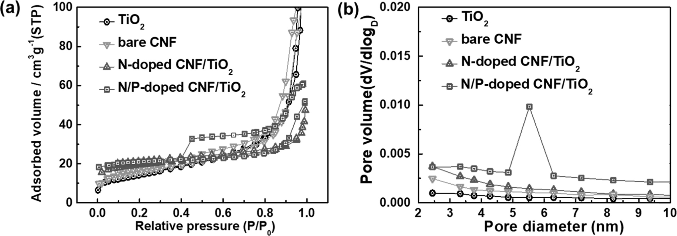
The porous structures of the TiO2 NP, bare CNF,
N-doped CNF/TiO2, and N/P-doped CNF/TiO2 samples were
examined by obtaining their N2 adsorption/desorption
isotherms using the BET method (Fig. 6). The TiO2
NP, bare CNF, and N-doped CNF/TiO2 samples exhibited
type-I isotherms, indicating the presence of micropores (pore width, <2 nm,
as classified by the International Union of Pure and Applied Chemistry) [37,
38]. The N/P-doped CNF/TiO2 composite showed a
type-IV isotherm, indicating the presence of mesopores (pore width,
2-50 nm) at high pressures (P/P0>0.4) [37, 38].
In other words, the N/P-doped CNF/TiO2 composite
showed different isotherm intervals, indicating that it showed a mesoporous
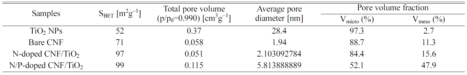
structure. The specific surface areas, total pore volumes, average pore
diameters, and pore volume fractions of all the samples are listed in Table 1.
It can be observed from the table that the N/P-doped CNF/TiO2
composite exhibited higher mesopore volume fraction than the TiO2
NPs, bare CNF, and N-doped CNF/TiO2 samples. To
further investigate the pore sizes and volumes of the samples, BJH
measurements were carried out. The results showed that the N/P-doped CNF/TiO2
composite had high mesopore volume and a pore size of 5-7 nm. Owing to the
difference in the atomic radii of C and P atoms, the doped P atoms increased
the specific surface area of the N/P-doped CNF/TiO2
composite by increasing its mesopore volume fraction.
The mesoporous structure of the N/P-doped CNF/TiO2 composite
shortened its lithium ion diffusion pathways, which is beneficial
for improving the performance of LIB electrodes [34].
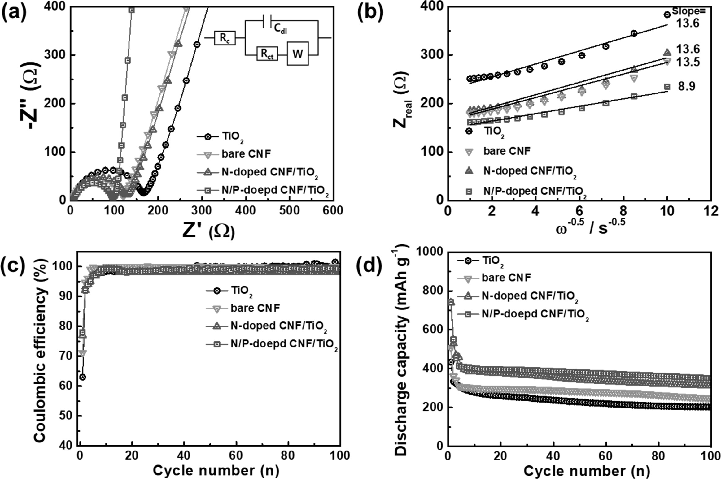
EIS measurements were carried out using fresh cells to
examine the electrochemical kinetics related to the lithium ion diffusion and
charge transfer resistance of the samples. The Nyquist plots for all the electrodes at
open-circuit potentials are shown in Fig.
7(a). The semicircle in the high-frequency
region corresponds to the charge transfer resistance (Rct) at the
electrode/electrolyte interface. The Rct values of the bare CNF, N-doped CNF/TiO2, and N/P-doped CNF/TiO2
electrodes were lower than that for
the TiO2 NP electrode [33, 39]. This suggests that the N-doped C
facilitated faster reaction kinetics
between the electrode and the electrolyte and increased the electrical
conductivity of the electrodes. In
addition, the slanted line in the low-frequency region represents the Warburg
impedance imputed to the interfacial diffusion resistance of lithium ions [33,
39]. The N/P-doped CNF/TiO2 electrode showed the lowest Warburg
impedance because of its shortest lithium ion diffusion pathway and highest
electrical conductivity. Thus, P-doping improves the high-rate performance of
CNF-based LIB electrodes. Moreover, the lithium ion diffusion coefficient could be derived from the
Warburg impedance slope, according to
the following equation [33, 39]:
Zreal =
Re + Rct + σWω-1/2 (1)
D = R2T2/2A2n4F4C2σ2W (2)
where σW is the
Warburg impedance coefficient, D is the lithium diffusion coefficient, R is the
gas constant, T is temperature, A is the electrode area, n is the
number of electrons/molecules, F is the Faraday’s constant, and
C is the molar concentration of lithium ions. Fig. 7(b) shows the relationship
between the Zreal and ω-1/2
of the samples in the low-frequency region. The σW values of
the TiO2 NP, bare CNF, N-doped CNF/TiO2, and N/P-doped
CNF/TiO2 electrodes were 13.6, 13.5, 13.6, and 8.9 Ωcm2 s-1/2,
respectively. Thus, the lithium ion diffusion coefficients of the TiO2
NP, bare CNF, N-doped CNF/TiO2, and N/P-doped CNF/TiO2
electrodes were calculated to be 1.78 × 10⁻¹³,
1.81 × 10⁻¹³,
1.79 × 10⁻¹³,
and 4.16 × 10⁻¹³,
respectively. These results show that the increase in the number
of mesopores by P doping shortened the lithium ion diffusion pathway of the
electrodes during cycling, thereby improving their lithium ion diffusion performance
to facilitate ultrafast charging/discharging.
The electrochemical performances of the electrodes were
evaluated by carrying out their cycling tests using coin-type cells. The
Coulombic efficiencies of the electrodes were measured at the current density
of 100 mA g-1
for 100 cycles, as shown in Fig. 7(c). The electrodes showed low Coulombic
efficiencies during the first cycle because of the formation of
solid-electrolyte interface (SEI) layers on their surfaces. As is well-known,
SEI layers are generally formed by the reductive decomposition of the
electrolyte components at the electrode surface, leading to an initial
irreversible reaction. The initial Coulombic efficiencies of the TiO2
NP, bare CNF, N-doped CNF/TiO2, and N/P-doped CNF/TiO2
electrodes were 63%, 71%, 77%, and 78%, respectively. This indicates that the
TiO2 NPs dispersed in the CNF matrix contributed to the high
Coulombic efficiencies of the composite electrodes during the first cycle. All
the samples showed a Coulombic efficiency of nearly
100% after six cycles, indicating the occurrence of highly
reversible LIB reactions.
Fig. 7(d) shows the cycling performances of all the
samples at the current density of 100 mA g-1
for 100 cycles. Fig. 7(c) shows that all the samples exhibited excellent
cycling stability after 100 cycles. The discharge-specific
capacities of the TiO2 NP, bare CNF, N-doped CNF/TiO2,
and N/P-doped CNF/TiO2 samples were measured to
be 202.6, 248.4, 311.9, and 351.5 mAh g-1,
respectively. The N-doped CNF/TiO2 and N/P-doped CNF/TiO2
electrodes showed higher discharge-specific capacities than the other two
samples because of the presence of well-dispersed TiO2 NPs in their
CNF matrices. These TiO2 NPs provided a large number of lithium
storage sites to the electrodes. In addition, the doped P atoms contributed to
the high discharge-specific capacity of the N/P-doped CNF/TiO2
electrode by increasing its specific surface area and the number of active
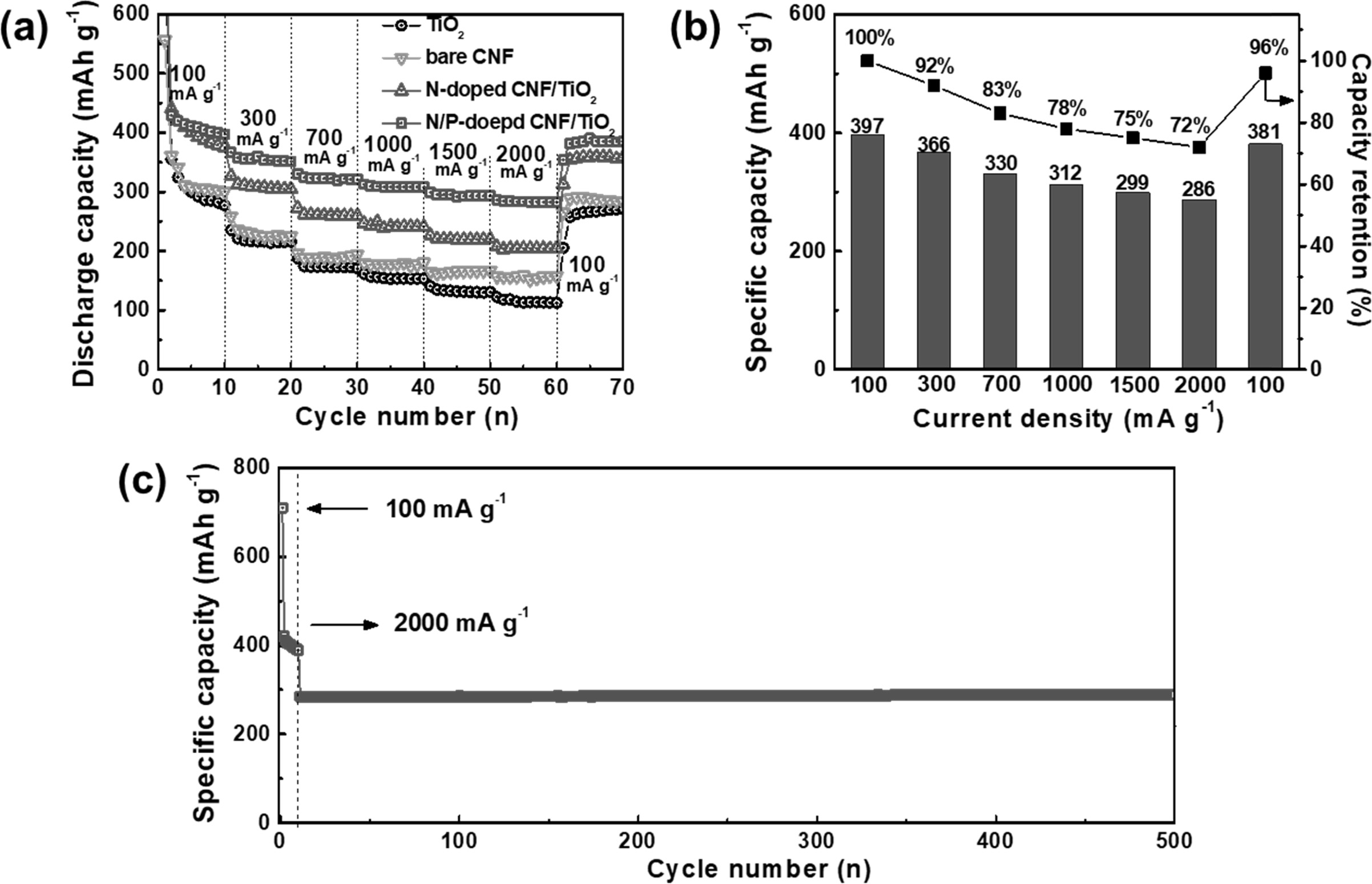
sites in it. With the rapid growth of the LIB industry, the need for electrodes
with ultrafast charge/discharge ability and cycling stability has increased
tremendously. The rate performances of the TiO2 NP, bare CNF,
N-doped CNF/TiO2, and N/P-doped CNF/TiO2 electrodes at
the current densities of 100, 300, 700, 1,000, 1,500, 2,000, and 100 mA g-1
are shown in Fig. 8(a). The specific capacity of the all the electrodes
decreased with an increase in the current density because of the reduction in
the time available for lithium ion diffusion. The TiO2 NPs showed
poor high-rate performance owing to their low ion conductivity. However,
N-doped C showed higher ion conductivity than TiO2 NPs. Hence, the
bare CNFs and N-doped CNF/TiO2 showed better high-rate performance
than the TiO2 NPs. The N/P-doped CNF/TiO2 electrode
showed the best high-rate performance among all the electrodes because of the
presence of P atoms in its CNF matrix. To further examine the
high-rate performance of N/P-doped CNF/TiO2,
its specific capacities and capacity retentions at different current densities
were determined (Fig. 8(b)). The capacity of N/P-doped CNF/TiO2
decreased from 397 to 381 mAh g-1
with an excellent capacity retention of 96% after the current density was
recovered to 100 mA g-1.
This ultrafast cycling capacity of N/P doped CNF/TiO2
can be attributed to its high mesopore volume caused by the doped P
atoms, which provided shorter ionic diffusion lengths and accelerated the
charge transfer. The N/P-doped CNF/TiO2 electrode showed ultrafast
cycling stability with a specific capacity of 285 mAh g-1
during 500 cycles (Fig. 8(c)). As TiO2 is a stable cycling material,
when it is compounded with a carbon matrix as the buffer layer for volume
expansion during ultrafast cycling, ultrafast cycling stability is achieved.
The ultrafast cycling stability of N/P-doped CNF/TiO2 can also be
attributed to the improvement in its electrical properties caused by the
synergistic effect of the doped N and P atoms. This resulted in the
uninterrupted supply of electrons and ions along with the formation of C-N and
C-P bonds under the ultrafast cycling condition. Fig. 5
|
Fig. 1 Schematic illustration of synthetic process for N/P-doped C/TiO2. (a) The stabilized PAN/TiO2 nanofibers after electrospinning process using TiO2 nanoparticles and PAN in DMF solution. (b) N/P-doped CNF/TiO2 after carbonization with red P. |
|
Fig. 2 FESEM images of TiO2, bare CNFs, N-doped CNF/TiO2, N/P-doped CNF/TiO2. |
|
Fig. 3 Low-resolution (a) and high-resolution (b) images of N/Pdoped C/TiO2. |
|
Fig. 4 (a) The XRD patterns of TiO2, bare CNFs, N-doped CNF/TiO2, and N/P-doped C/TiO2. (b) TGA curves of TiO2, N-doped CNF/TiO2, N/P-doped CNF/TiO2 from 200 to 900°C at heating rate of 10°C min−1 under air. |
|
Fig. 5 XPS spectra of Ti 2P, N 1s, P 2p of TiO2 (a, d, and g), N-doped C/TiO2 (b, e, and h), and N/P-doped C/TiO2 (c, f, and i). |
|
Fig. 6 (a)The N2 adsorption/desorption isotherms. (b) The BJH pore size distributions of TiO2, bare CNF, N-doped C/TiO2, and N-P doped C/TiO2. |
|
Fig. 7 (a) Nyquist plots in the frequency range of 105-10−2 Hz and (b) the relationships between Zreal and ω−1/2 in low frequency range, (c) coulombic efficiency, and (d) cycling stabilities of TiO2, bare CNF, N-doped C/TiO2, and N/P-doped C/TiO2 electrodes at 100 mA g−1 during 100 cycles. |
|
Fig. 8 (a) The rate performance, (b) the detailed specific capacities and capacity retentions at various current densities of 100, 300, 700, 1,000, 1,500, and 2,000 mA g−1, and (c) ultrafast cycling stability at current density of 2,000 mA g−1 over 500 cycles of N/P-doped C/TiO2 electrode. |
|
Table 1 Specific surface areas, Total pore volumes, Average pore diameters, and Pore volume fractions of TiO2 NPs, bare CNF, N-doped CNF/TiO2, and N/P-doped CNF/TiO2. |
In this study, we synthesized a N/P-doped CNF/TiO2
composite for application as an LIB anode using the hydrothermal,
electrospinning, and carbonization techniques. TiO2
NPs were well-dispersed in the N/P-doped CNF matrix. The N/P-doped CNF/TiO2
electrode showed outstanding LIB performance with excellent specific capacity
(351.5 mAh g-1
at 100 mA g-1
after 100 cycles), high rate performance (286 mAh g-1
at 2000 mA g-1),
and ultrafast cycling stability (285 mAh g-1
at 2000 mA g-1
after 500 cycles). This excellent LIB performance of the
electrode can be attributed to the following: (I) the improved specific
capacity and a large number of lithium storage sites offered by the TiO2
NPs, which were well-distributed in the CNF matrix; (II) the increased specific
surface area caused by the increase in the number of mesopores, offering
shorter lithium ion diffusion lengths; (III) the excellent electrical
properties offered by the synergistic effects of the N and P
dopants, leading to a continuous and uninterrupted supply of
electrons and ions along with the formation of C-N and C-P bonds under the
ultrafast cycling condition.
This study was supported by the Research Program funded by
the SeoulTech (Seoul National University of Science and Technology)
- 1. M. Armand and J. -M. Tarascon, Nature 451 (2008) 652-657.
-

- 2. P. G. Bruce, B. Scrosati, and J.-M Tarascon, Angew. Chem. Int. Ed. 47 (2008) 2930-2946.
-
- 3. Y.-T. Park and K.-T. Lee, J. Ceram. Process. Res. 19[3] (2018) 257-264.
- 4. G.-H. An, D.-Y. Lee, and H.-J. Ahn, ACS Appl. Mater. Interfaces 8 (2016) 19466-19474.
-
- 5. G.-H. An, D.-Y. Lee, Y.-J. Lee, and H.-J. Ahn, ACS Appl. Mater. Interfaces 8 (2016) 30264-30270.
-
- 6. G.-H. An, J.I. Sohn, and H.-J. Ahn, J. Mater. Chem. A 4 (2016) 2049-2054.
-
- 7. G.-H. An, D.-Y. Lee, and H.-J. Ahn, ACS Appl. Mater. Interfaces 9 (2017) 12478-12485.
-
- 8. Y.-T. Park, Y. K. Hong, and K.-T. Lee, J. Ceram. Process. Res. 18[7] (2017) 488-493.
- 9. M. Qi, Y. Zhong, M. Chen, Y. Dai, and X. Xia, J. Alloy. Compd. 750 (2018) 715-720.
-
- 10. Y. Teng, M. Mo, Y. Li, J. Xue, and H. Zhao, J. Alloy. Compd. 744 (2018) 712-720.
-
- 11. C. Zhu, C.-G. Han, G. Saito, and T. Akiyama, J. Alloy. Compd. 689 (2016) 931-937.
-
- 12. M. Li, X. Li, W. Li, X. Meng, Y. Yu, and X. Sun, Electrochem. Commun. 57 (2015) 43-47.
-
- 13. S. Brutti, V. Centili, H. Menard, B. Scrosati, and P.G. Bruce, Adv. Enegy Mater. 2 (2012) 322-327.
-
- 14. G. Zampardi, E. Ventosa, F. L. Mantia, and W. Schumann, Chem. Commun. 49 (2013) 9347-9349.
-
- 15. D. Bresser, E. Paillard, E. Binetti, S. Krueger, M. Striccoli, M. Winter, and S. Passerini, J. Power Sources 206 (2012) 301-309.
-
- 16. Z. Yang, D. Choi, S. Kerisit, K. M. Rosso, D. Wang, J. Zhang, G. Graff, and J. Liu, J. Power Sources 192 (2009) 588-598.
-
- 17. M.-C. Kim, Y.-W. Lee, S.-J. Kim, B.-M. Hwang, H.-C. Park, E.-T. Hwang, G. Cao, and K.-W. Park, Electrochim. Acta 147 (2014) 241-249.
-
- 18. Z. Wang, J. Sha, E. Liu, C. He, C. Shi, J. Li, and N. Zhao, J. Mater. Chem. A 2 (2014) 8893-8901.
-
- 19. B.-S. Lee, S.-B. Son, K.-M. Park, J.-H. Seo, S.-H. Lee, I.-S. Choi, K.-H. Oh, and W.-R. Yu, J. Power Sources 206 (2012) 267-273.
-
- 20. Y. Chen, P. Jiang, W. Dong, and B. Huang, Renew. Energy 84 (2015) 130-137.
-
- 21. X. Ki, B. Zhou, W. Wang, Z. Xu, N. Li, L. Kuang, C. Li, W. Mai, H. Fu, and H. Lv, J. Alloy. Compd. 706 (2017) 103-109.
-
- 22. B. Xu, S. Hou, G. Cao, F. Wu, and Y. Yang, J. Mater, Chem. 22 (2012) 19088-19093.
-
- 23. Z. Li, Z. Xu, X. Tan, H. Wang, C. M. B. Holt, T. Stephenson, B. C. Olsen, and D. Mitlin, Energy Environ. Sci. 6 (2013) 871-878.
-
- 24. J.P. Paraknowitsch and A. Thomas, Energy Environ. Sci. 6 (2013) 2839-2855.
-
- 25. K. Wang, M. Xu, X. Wang, Z. Gu, Q. H. Fan, W. Gibbons, and J. Croat, RSC Adv. 7 (2017) 8236-8240.
-
- 26. Y. Zhang, W. Dai, Y. Liu, and B. Ma, RSC Adv. 7 (2017) 8250-8257.
-
- 27. H. Chen, F. Sun, J. Wang, W. Li, W. Qiao, L. Ling, and D. Long, J. Phys. Chem. C 117 (2013) 8318-8328.
-
- 28. D. Zhang, L. Zheng, Y. Ma, L. Lei, Q. Li, Y. Lim, H. Luo, H. Feng, and Y. Hao, ACS Appl. Mater. Interfaces 6 (2014) 2657-2665.
-
- 29. S. Some, J. Kim, K. Lee, A. Kulkarni, Y. Yoon, S. Lee, T. Kim, and H. Lee, Adv. Mater. 24 (2012) 5481-5486.
-
- 30. G.-H. An and H.-J. Ahn, J. Power Sources 272 (2014) 828-836.
-
- 31. G.-H. An, S.-J. Kim, K.W. Park, and H.-J. Ahn, ECS Solid State Lett. 3 (2014) M21-M23.
-
- 32. G.-H. An, E.-H. Lee and, H.-J. Ahn, Phys. Chem. Chem. Phys. 18 (2016) 14859-14866.
-
- 33. K. P. Singh, E. J. Bae, and J.-S. Yu, J. Am. Chem. Soc. 137 (2015) 3165-3168.
-
- 34. G.-H. An and H.-J. Ahm, J. Alloy. Compd. 710 (2017) 274-280.
-
- 35. Y. Liang, N. Li, F. Li, Z. Xu, Y. Hu, M. Jing, K. Teng, X. Yang, and J. Shi, Electrochim. Acta 297 (2019) 1063-1070.
-
- 36. D.-Yo. Shin, K.-W. Sung, and H.-J. Ahn, Appl. Surf. Sci. 478 (2019) 499-504.
-
- 37. G.-H. An, T.-K. Lee, and H.-J. Ahn, J. Korean Powder Metall. Inst. 22 (2015) 367-375.
-
- 38. G.-H. An, B.-R, Koo, and H.-J. Ahn, Phys. Chem. Chem. Phys. 18 (2016) 6587-6594.
-
- 39. G.-H. An and H.-J. Ahn, Carbon 65 (2013) 87-96.
-
 This Article
-
2020; 21(2): 269-277
Published on Apr 30, 2020
- 10.36410/jcpr.2020.21.2.269
- Received on Nov 28, 2019
- Revised on Jan 10, 2020
- Accepted on Jan 17, 2020
Services
- Abstract
introduction
experiments
results and discussion
conclusions
- Acknowledgements
- References
- Full Text PDF
Shared
Correspondence to
- Hyo-Jin Ahn
-
Department of Materials Science and Engineering, Seoul National University of Science and Technology, Seoul 01811, Korea
Tel : +82-2-970-6622 Fax: +82-2-973-6657 - E-mail: hjahn@seoultech.ac.kr
Clean-Energy Research Institute(CRI), Hanyang University, 222, Wangsimni-ro, Seongdong-gu, Seoul, 04763, Korea
E-mail: jcpr@hanyang.ac.kr