


- Manufacture of rapid SiC heating element and increased durability through glass frit coating
Jae Uk Hura,** , Jung Hun Kimb,**, Gye Seok Ana,* and Sung-Churl Choia
a Division of Materials Science and Engineering, Hanyang University, 222 Wangsimni-ro, Seongdong-gu, Seoul 04763, Korea
bCeramicware Technology Center, Korea Institute of Ceramic Engineering & Technology, 3321 Gyeongchung-daero, Sindun-myeon, Icheon 17303, Korea
We investigated the optimal
conditions for the manufacture of a rapid SiC heating element with increased
durability for a flip chip bonder. In the moulding step prior to the sintering
of the SiC heating element, a pressure of either 25 or 125 MPa was applied by
uniaxial pressing to control the micropores; this was aimed at improving the
resistance of the ultimate specimen. The moulded specimen was sintered by using
a vacuum furnace with silicon as a sintering additive. The measurement of the
hot modulus of rupture (HMOR) of the resulting SiC sintered body revealed that
the HMOR was high. In addition, a method for protecting the heating element
from the external environment was developed. A glassy coating layer was
deposited on the surface of the structure to improve the corrosion resistance
of the sintered body; further, the performance of the coating layer was
verified through a neutral and acidic salt spray test. Finally, we established
the optimal process conditions for manufacturing a rapid SiC heating element
with improved corrosion resistance.
Keywords: Heating element, Silicon carbide, Glass coating, Corrosion resistance
The improvement of semiconductor manufacturing technology
is a driving force that facilitates the develop- ment of next-generation
semiconductor equipment and the relevant components and materials. There is a
necessity to increase the manufacturing speed of high-end
semiconductors, such as those used in smart phones and tablet
PCs, and to further reduce the percentage of manufacturing defects. This is
being achieved by the rapid replacement of the wire bonder-based method with
the flip chip bonder-based method [1-3]. The flip chip bonder-based method,
where a printed circuit board (PCB) is connected with a chip by solder ball
bumping, can be applied to precise processes. This is because its high heat
radiation rate, energy efficiency, and precision enable the reduction of the
amount of defects in the manufacturing process, which then increases
productivity; further, the conventional wire bonding is avoided in this case
due to the compactness of the device and the processing speed [4, 5].
The core of the flip chip bonder equipment is the heating
element inside the bonder. A heating element that can rapidly radiate heat is
employed in the semiconductor process to enable rapid processing. Silicon
carbide (SiC) is used as the material for the flip-chip
bonder heating element because it has excellent physical,
electrical, and thermal properties, and also demonstrates good corrosion and
heat resistance [6-10]. However, due to the low electrical
conductivity (s = 10-13 S m-1) of SiC, it is
difficult to apply SiC alone to a heating element; therefore, a method for
increasing the conductivity is needed [11, 12].
Conversely, parts of the flip chip bonder heating element
undergo oxidation because of the gaseous atmosphere used in the process and the
rapid heating and cooling cycles. The oxidation can decrease product quality
and reduce the lifetime of the heating element [13]. An effective protective
layer to shield the heating element from the extreme external environment is
necessary to solve the problem.
In the present study, the optimum conditions for the manufacture
of rapid SiC heating element with increased durability
through a simple process were investigated. We sintered SiC under vacuum using
Si as a sintering additive. Further, the porosity of the heating element was
controlled during the manufacturing the flip chip bonder heating element; this
control was aimed at achieving a rapid heating performance. In addition, a
glassy protective layer was formed by coating the surface of the manufactured
heating element with a solution containing glass frit to increase the oxidation
resistance.
Preparation
of specimens at different pressures
Commercially available silicon carbide (ß-SiC, 99.8%
purity, 1 μm, Alfa Aesar, USA) and silicon powder (Si, 99.9% (metals basis),
Alfa Aesar, USA) were used without further processing. The SiC and Si powder
were mixed at a volumetric ratio of 6:4. The SiC/Si mixture (2.5 g) was charged
into a mould, and a load either 25 or 125 MPa was applied through uniaxial pressing
using an oil-hydraulic press to obtain specimens with dimensions of 20
mm × 20 mm × 2 mm. The processed
specimens were sintered using a vacuum furnace
under vacuum. During sintering, the temperature was increased to 1,400 oC at a rate of 10 oC/min
and kept constant for 30 min. The temperature was then increased to 1,600 oC,
the final sintering temperature, at a rate of 5 oC/min and kept
constant for 1.5 h. The specimens were subsequently allowed to cool to room
temperature at a natural, uncontrolled rate to prepare the final SiC/Si
specimens.
Formation
of oxidation resistive coating layer
The SiC specimens were dip-coated. First, 100 cc of a
mixed solution was prepared using isopropyl alcohol (IPA, 99.9%, DUKSAN, Korea)
and ethyl cellulose (EC, C23H24N6O4,
Sigma-Aldrich, USA) at a mixing ratio of 90:10 (vol%). To the prepared mixed
solution, 50 g to 150 g of glass frit (S-4000, coefficient of
thermal expansion: 75.8 × 10⁻⁷/oC,
SHINCERAMIC Co., LTD., Korea) was added, and the resulting mixture was
mechanically stirred to prepare a coating solution. The sintered
specimen was dip-coated in the coating solution and dried at
70 oC for 2 h. Thermal treatment of the specimen was then
performed using an electric furnace, increasing the temperature to 220 oC
at a rate of 5 oC/min and keeping the temperature constant for
2.5 h, and then increasing the temperature to 650 oC and keeping
it constant for 2 h. Following thermal treatment, the
specimen was allowed to cool to room temperature at a natural, uncontrolled
rate to prepare the final specimen with an oxidation resistive coating layer.
Analysis
The microstructure was analysed using field-emission
scanning electron microscopy (FE-SEM, JSM-7610F, JEOL, Japan) and the porosity
of the moulded bodies was measured using mercury porosimetry (Model PoreSizer
9320, Micrometrics Instrument Group, Norcross, GA). The
time-dependent variation of the current of the specimens prepared at different
press pressures was measured using a switching type programmable DC
power supply (EX30-120, 30V/120A, ODA TECHNOLOGIES, Korea). The
hot modulus of rupture (HMOR) of the prepared specimens at 400 oC
was measured by using HBTS 422 equipment (3-point bending test, Netzsch,
Germany) at a loading speed of 0.3 mm/min. For the measurement,
the specimens were processed in dimensions of 3
mm × 4 mm × 40 mm.
To verify the corrosion prevention performance of the
coated specimens, a salt spray test was performed with either a neutral or
acidic solution. The neutral salt spray test was performed by exposing the
specimens to a 5% NaCl mist at pH 7.1 and keeping the spray temperature
constant (Chamber ambient temperature: 35 ºC, Salt spray temperature:
37 ºC) for 96 h. The acetic acid salt spray (AASS) test was performed by
spraying an acetic acid salt solution, titrated to pH 3.0, at
a constant temperature (Chamber ambient temperature: 35ºC, Salt
spray temperature: 37ºC) onto the specimens for 48 h.
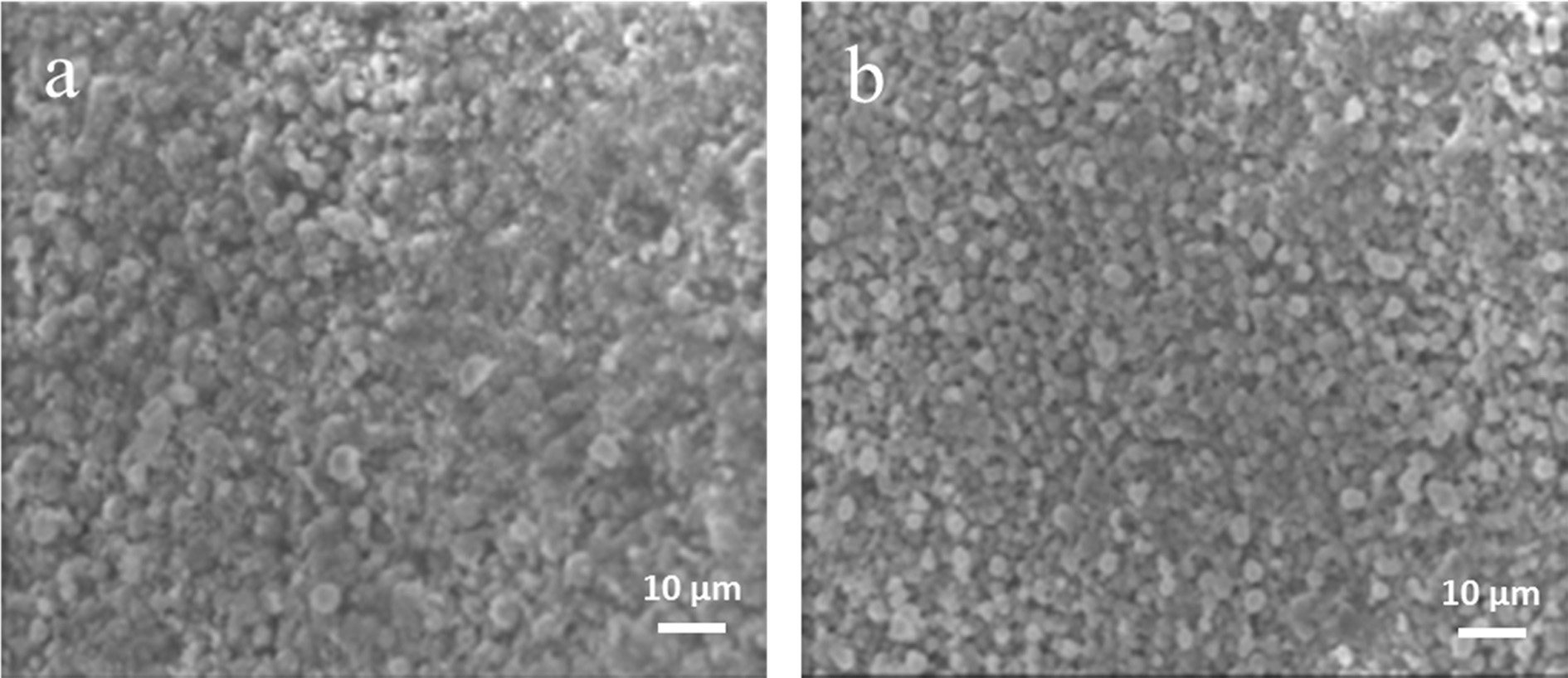
Fig. 1 presents SEM images showing the surface morphology
of the sintered bodies at different press pressures. In the sintered body
prepared by applying 125 MPa, the particles were broken and coagulated,
resulting in the collapse of the pores. The sintered body prepared by applying
25 MPa showed a more uniform particle distribution without particle
destruction.
A pore characteristic analysis was performed to measure
the porosity of the sintered bodies depending on the pressure. The porosity was
23.9% in the sintered body prepared under 125 MPa and 33.49% under 25 MPa. As
shown by the pore characteristic analysis, the porosity of the moulded bodies
was significantly dependent upon the pressure load: as the press pressure
increased, the porosity greatly decreased.
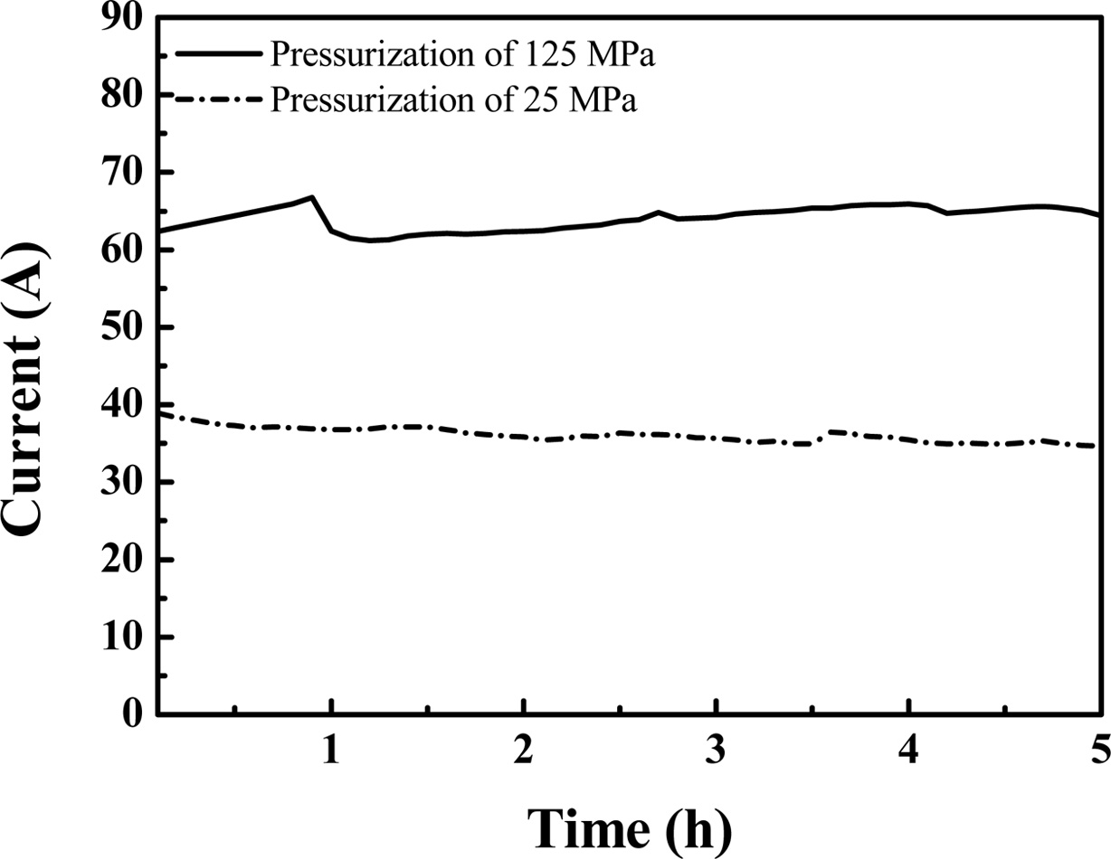
Fig. 2 shows the time-dependent variation of the current
of the SiC sintered body at different press pressures. When the specimen was
prepared with a press pressure of 125 MPa, the average current of the SiC sintered body was
approximately 65 A at 12 V. Although this sintered body satisfies the required performance for a rapid heating element, the
instantaneous heating may not be
controlled when it is applied for the flip chip bonder equipment. The specimen
prepared by applying a lower press pressure of 25 MPa showed an average current
of approximately 34 A at 12 V, indicating that a resistance range suitable for
a heating element was obtained. Specimens prepared by applying a press pressure
lower than 25 MPa showed either a lack of moldability or a severe decrease of
strength after sintering, making the specimens unsuitable. The relatively high
porosity of the specimen prepared by applying 25 MPa may have increased its
electrical resistance. Therefore, moulding the specimens at a low pressure
before the sintering allows the formation of abundant pores, although the
density of the structure may become relatively low. The pores decrease the
electric conductivity of the specimens and increase the resistance, and the specimens thereby could
successfully serve as rapid heating
elements.
Considering that the prepared specimens are to be used as
a heating element for a flip chip bonder, the strength in a high-temperature
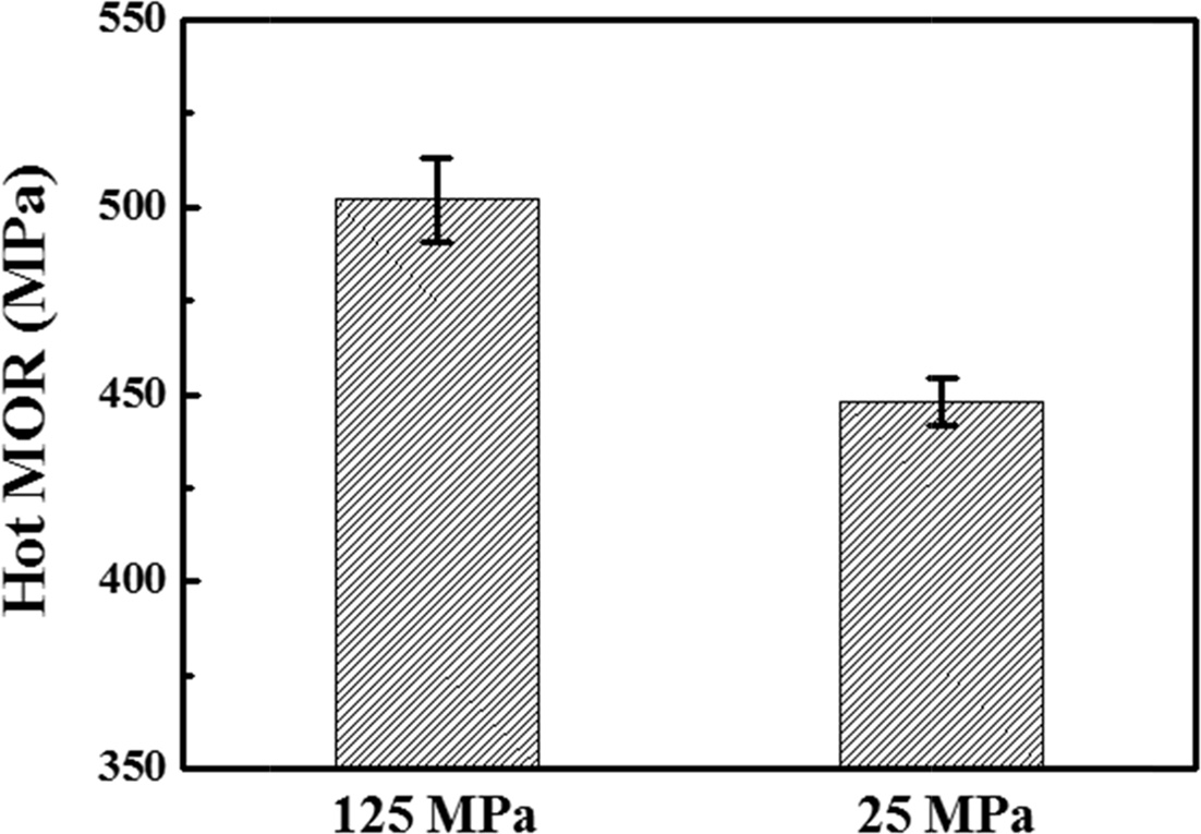
environment is a critical property. The HMOR of the specimens prepared under
different press pressures was measured to verify their physical properties in a
high-temperature environment, and the results are shown in Fig. 3. The error
bars shown in the measurement data represent the range of the measurement
values obtained from five samples prepared under identical conditions in order
to ensure reliability. The three-point HMOR values at 400 oC of
the specimens prepared by applying press pressures of 125 MPa and 25 MPa were
approximately 502 MPa and 448 MPa, respectively, indicating
that both specimens had sufficiently high HMOR values. The data shows
that an initial moulded body prepared under a higher load gives a higher HMOR
after being prepared as a sintered body. However, considering the porosity and previously measured
current values, the specimen prepared by
applying 25 MPa may be more appropriate for application as a rapid heating
element. Therefore, further experiments were performed using only the specimens
prepared at this pressure.
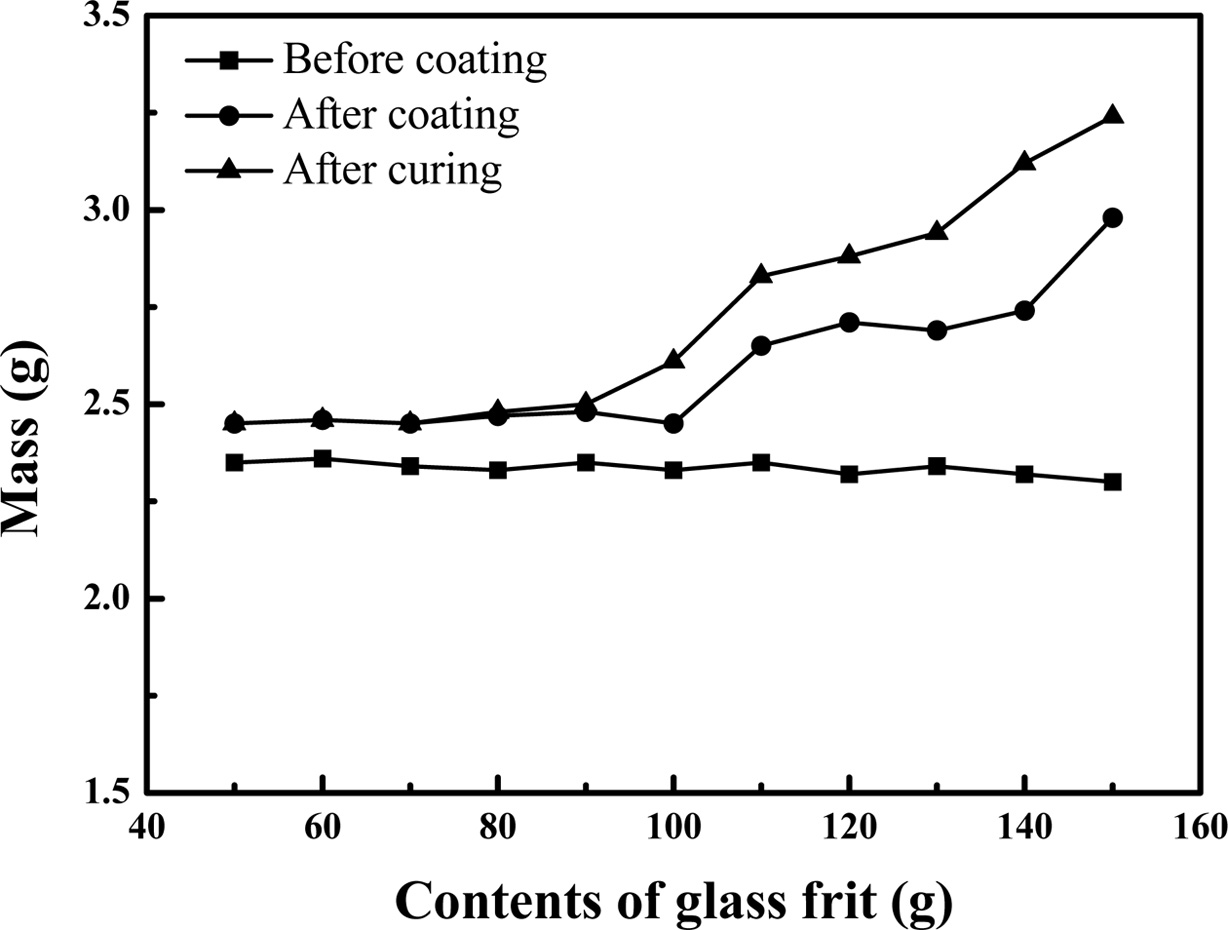
Fig. 4 shows the mass increase of the specimens after dip
coating as a function of the glass frit content of the coating solution. Even when
the amount glass frit in the solution was increased, the weight of the coated
specimens did not change significantly. However, as the glass frit content of
the coating solution increased to 100 g or more, the mass of the sample after
curing also increased. In the cases where the glass frit content was 90 g or
less, a primary glass frit coating layer formed between the pores of the
sintered body, and the coating on top of the primary coating layer was not
thick. However, when the coating solution contained a glass frit
content of 100 g or more, a thick glass coating layer
was formed through curing. The excessive addition of the glass
frit may have increased the viscosity of the coating solution, resulting in an
increase of the coating solution remaining on the specimen surface during the
dip coating process.
The
glassy layer formed on the surface should be capable of protecting the heating
element from the external environment when used in a flip chip bonder, and at
the same time, should not have a negative effect on the heat radiation
performance during rapid heating. Therefore, the acquired experimental data
suggests that an oxidation resistance coating layer may be formed in a stable
manner by performing the dip coating process
using a coating solution containing 80 g of glass frit.
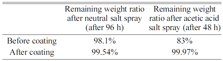
A salt spray test was performed to evaluate the corrosion
resistivity of the specimens on which a glassy coating
layer was formed by using a coating solution containing 80
g of glass frit. Table 1 shows the remaining weight ratio
before and after the coating. In the neutral salt spray test, the specimens did
not show a significant difference with or without the
oxidation resistive coating. On the contrary, in the acetic acid
salt spray test, the specimen showed a mass loss of approximately 17% without
the oxidation resistive coating. The mass loss may have been due to the
reactions between the metal components contained in the specimens and the
acidic solution. After the formation of the oxidation resistive coating layer,
the mass loss was only 0.03%, indicating that there was almost no change in the
remaining mass. The low mass loss may be because both the strong resistance of
the glassy oxidation resistive layer to acidic environments and the uniform
formation of the coating layer on the surface of the SiC heating element
samples protected the specimen.
|
Fig. 1 Cross-sections of sintered bodies prepared at different pressures applied by the press. (a) Specimen prepared by applying 125 MPa; and (b) specimen prepared by applying 25 MPa. |
|
Fig. 2 Time-dependent variation of current through the SiC sintered bodies formed under press pressures of 125 MPa and 25 MPa at equal voltages. |
|
Fig. 3 Three-point HMOR (400 oC) of the specimens prepared under different pressures. |
|
Fig. 4 Mass of coating depending on glass frit content in coating solution. |
|
Table 1 Remaining weight ratio before and after oxidation resistive coating in corrosion resistance test. |
In the present study, we fabricated SiC heating elements
with a rapid heating performance; this was achieved by controlling the porosity
of the specimens through the application of a pressing load of either 25 or 125
MPa. The SiC was sintered with Si in a furnace under vacuum
at a relatively low temperature. In addition, the
sintered specimens were dip-coated with a coating solution prepared with
different quantities of glass frit in the solution; further, the mass change
before and after the coating and after curing was analysed to derive the
optimal coating conditions. The neutral and acidic salt spray tests revealed
that the glassy coating layer formed on the heating element could sufficiently
protect the SiC heating element. The results showed that the optimal process
conditions include a load of 25 MPa applied to the sintered body for providing
a high porosity of 33.49% to increase the resistance; further, a coating
solution with a glass frit content of 80 g was applied, which forms an
effective oxidation resistive coating layer on the surface.
This work was supported by grants (NRF-2018R1A5A6075959) from the National Research
Foundation of Korea (NRF) funded by the Korean Government and by grants
(2019-A-G020-01010) from the Leaders in Industry-university Cooperation+
and project for ‘New business R&D Voucher’ between Industry, Academy, and
Research Institute funded Korea Ministry of SMEs and Startups in 2019. (project
No.S2718404).
- 1. J.W. Kim, D.G. Kim, W.S. Hong, and S.B. Jung, J. Electron. Mater. 34 (2005) 1550-1557.
-

- 2. K. Yamashita, S. Kurooka, K. Shirakawa, Y. Hotta, and H. Abe, in Proceedings of 2015 International 3D Systems Integration Conference (3DIC), April 2015, edited by M. K Radhakrishnan (IEEE Press, 2015) TS8.1.1-TS8.1.5.
-
- 3. H.S. Yang, C. Zhang, and M.S. Bakir, IEEE Trans. Components, Packag. Manuf. Technol. 6 (2016) 471-477.
-
- 4. J.W. Nah, M.A. Gaynes, C. Feger, S. Katsurayama, and H. Suzuki, in Proceedings of the Electronic Components and Technology Conference, May 2011, edited by S. Gorshe (IEEE Press, 2011) p.1015-1022.
-
- 5. T. Enami, K. Nanami, O. Horiuchi, Y.G. Han, and H. Tomokage, in Proceedings of the Electronics Packaging and Technology Conference, December 2015, edited by D. Abbott (IEEE Press, 2015) p.1-6.
-
- 6. G. V. Clatterbaugh, C. V. Banda, and S.J. Lehtonen, Johns Hopkins APL Technical Digest, Applied Phys. Lab. 28 (2008) 47-58.
- 7. M. Steen and L. Ranzani, Ceramics. Int. 26 (2000) 849-854.
-
- 8. K. Pelissier, T. Chartier, and J.M. Laurent, Ceram. Int. 24 (1998) 371-377.
-
- 9. C.P. Deck, G.M. Jacobsen, J. Sheeder, O. Gutierrez, and J. Zhang, J. Stone, H.E. Khalifa, and C.A. Back, J. Nucl. Mater. 466 (2015) 667-681.
-
- 10. J.H. Choi, S. Kim, S.H. Kim, I.S. Han, Y.H. Seong, and H.J. Bang, J. Ceram. Process. Res. 20 (2019) 48-53.
- 11. G. Sauti, A. Can, D.S. McLachlan, and M. Herrmann, J. Am. Ceram. Soc. 90 (2007) 2446-2453.
-
- 12. B. Román-Manso, E. Domingues, F.M. Figueiredo, M. Belmonte, and P. Miranzo, J. Eur. Ceram. Soc. 35 (2015) 2723-2731.
-
- 13. A. Yamauchi, in Proceedings of the Electronic Components and Technology Conference, May 2000, edited by D. Verret (IEEE Press, 2000) p.1743-1746.
-
 This Article
-
2020; 21(2): 213-216
Published on Apr 30, 2020
- 10.36410/jcpr.2020.21.2.213
- Received on Nov 1, 2019
- Revised on Feb 5, 2020
- Accepted on Feb 7, 2020
Services
- Abstract
introduction
experimental procedure
results and discussion
conclusions
- Acknowledgements
- References
- Full Text PDF
Shared
Correspondence to
- Jae Uk Hur a, Jung Hun Kim b, Gye Seok An a
-
a Division of Materials Science and Engineering, Hanyang University, 222 Wangsimni-ro, Seongdong-gu, Seoul 04763, Korea
bCeramicware Technology Center, Korea Institute of Ceramic Engineering & - E-mail: faustmaro@hanyang.ac.kr
Clean-Energy Research Institute(CRI), Hanyang University, 222, Wangsimni-ro, Seongdong-gu, Seoul, 04763, Korea
E-mail: jcpr@hanyang.ac.kr