


- Effect of La0.8Ca0.2Cr0.9Co0.1O3−δ infiltration on the LCCC-YSZ layer as an interconnector material in solid oxide fuel cells
Ho-Chang Lee, Jiwon Lee, Jung-A Lee, Young-Woo Heo, Joon-Hyung Lee* and Jeong-Joo Kim*
School of Materials Science and Engineering, Kyungpook National University, Daegu 41566, Republic of Korea
Full densification of the
interconnector La0.8Ca0.2Cr0.9Co0.1O3−δ
(LCCC) layer is hardly achieved when it is screen-printed and cofired on a
pre-sintered NiO-YSZ (yttria-stabilized zirconia, 8YSZ) substrate. In this
study, the LCCC precursors with different concentrations and viscosities were
prepared and infiltrated into the LCCC-YSZ layer. The phase development process
and densification behavior of the LCCC were analyzed, and the optimum
conditions for full densification are suggested. Through the research, we
propose a method for manufacturing a dense LCCC interconnector layer.
Keywords: Sintering, Ceramics, Interconnector, Sol-gel preparation, Infiltration
Solid oxide fuel cells (SOFCs) consist of electrolytes,
anodes, and interconnectors. The interconnector acts as a physical barrier to
avoid any contact between the reducing and oxidizing atmospheres.
The interconnector must exhibit excellent electrical conductivity and
adequate dimensional, microstructural, chemical,
and phase stability at operating temperatures of
approximately 800 °C under both reducing and oxidizing atmospheres.
Furthermore, the thermal expansion coefficient of the interconnector should
match with those of the electrodes and electrolyte [1-3].
Only a few oxide systems can satisfy the rigorous requirements
of SOFC interconnectors. LaCrO3 is currently the
most widely used material [4, 5] for doping at either
La or Cr sites, or at both sites [5], and various synthesis methods have been
used to increase the sinterability [6-8]. Owing to their similar ionic radii,
Sr and Ca tend to replace La ions, whereas Mg, Fe, Ni, Cu, and Co tend to
replace Cr ions.
It has been previously reported that the doping of LaCrO3
with Ca and Co (La0.8Ca0.2Cr0.9Co0.1O3−δ,
LCCC) greatly improves its density. However, significant tensile stress was observed on the LCCC layer when
an LCCC interconnector was screen-printed and cofired on a pre-sintered NiO-YSZ
(yttria-stabilized zirconia, 8YSZ) substrate, which resulted in the
densification retardation of the LCCC layer. This phenomenon could be overcome
by the addition of YSZ, which is a constituent of the anode, to the LCCC [9].
In this study, the ethylene glycol-based LCCC solution
was infiltrated into the LCCC-YSZ (LCCC70 wt.% − YSZ30
wt.%) interconnector layer to enhance its density. The LCCC concentration of
the precursor solution and the heating rate during sintering were controlled.
It was found that the viscosity of the solution varied with
synthesis time because a cross-linking reaction
occurred simultaneously during polymerization. When
the synthesis was conducted at a high temperature, the sol
became volatile. Upon prolonging the synthesis period,
the LCCC concentration of the precursor solution changed and affected the
viscosity. Following the infiltration, the local temperature difference during
sintering caused a change in the viscosity and affected the final
microstructure.
The precursor solutions used for the infiltration process
were prepared from La(NO3)3·6H2O (Alfa Aesar,
99.9%), Ca(NO3)2·4H2O (Alfa Aesar, 99.9%), Cr(NO3)3·6H2O
(Alfa Aesar, 99.9%), and Co(NO3)3·6H2O
(Junsei, 99.9%). The concentration of the precursor solution was 0.2 M [10-11]
and the atomic ratio of La:Ca:Cr:Co was 0.8:0.2:0.9:0.1. The starting materials
were dissolved in distilled water, followed by the addition of
ethylene glycol and nitric acid. The precursor solution
used for the infiltration was heated at 95 °C and stirred for durations
varying from 1 to 5 d. Each precursor solution was heat-treated at
1,400 °C. The LCCC concentration was determined by measuring the mass of
the remaining powder. An X-ray diffractometer (X’Pert PRO, PANalytical) with Cu
Ka radiation was used to monitor the phase
transformation of the precursor solutions that were heat-treated
from 200 to 1,400 °C.
The substrate was prepared using NiO (Sumitomo Chemical
Co., 99.9%) and YSZ (Unitec, 99.9%) powders as raw
materials. The homogeneously mixed powder with a weight ratio of NiO:YSZ =
56:44 formed substrates with thickness of 1 mm, which were then pre-sintered at
1,250 °C. The LCCC-YSZ paste was printed onto a NiO–YSZ substrate using a
150-mesh screen. The bilayer specimens were cofired at 1,400 °C for 2 h in
air. To investigate the effect of infiltration in the interconnector layer, each
precursor solution was impregnated on the sintered bilayer specimens, which
were then sintered at 1,400 °C for 2 h in air at a heating rate of either
1 or 5 °C/min. The cross-section and surface of each sample were examined
using a field-emission scanning electron microscope (FE-SEM, JSM-6701F, JEOL)
with 10 kV and 10 μA. The viscosities of each solution were measured at room
temperature using a rotational rheometer (MCR301, Anton Paar) with 50 mm
diameter of the plate and 1 mm of the gap between the plates.
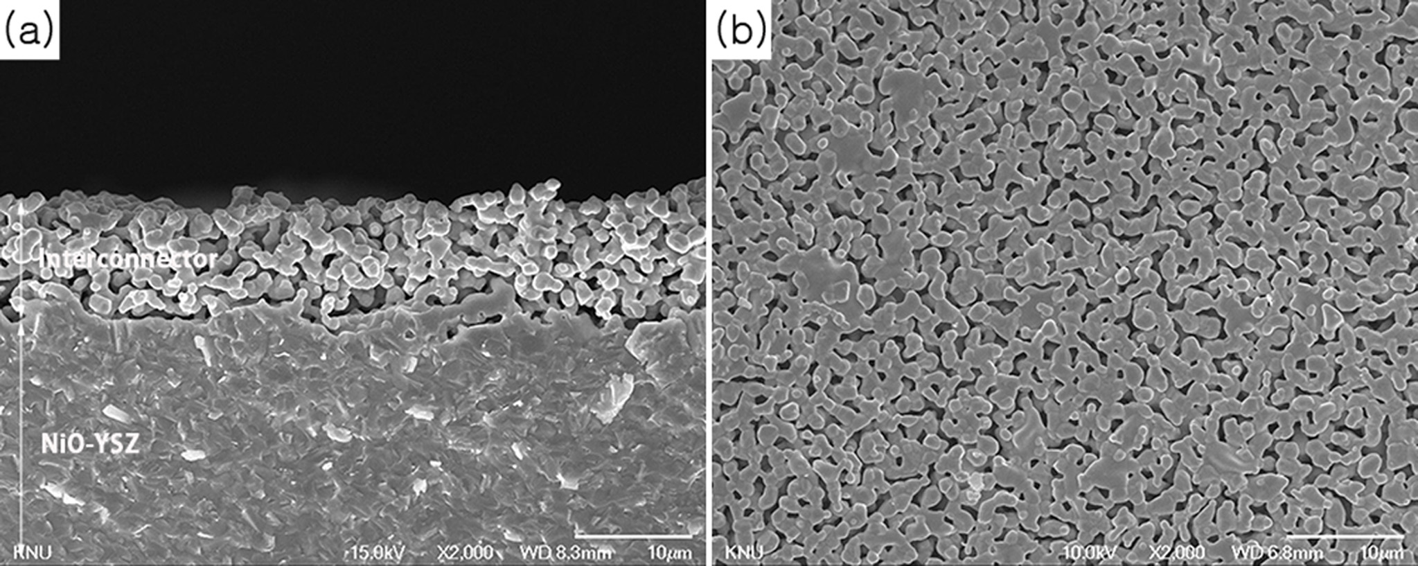
Fig. 1 shows the microstructures of the cross-section and
top surface of the screen-printed LCCC-YSZ layer on the NiO-YSZ anode
substrate. There was no reaction between NiO-YSZ and the LCCC-YSZ paste at
1,400 °C, as shown in the XRD patterns in a previous study
[9]. The calculated porosity was ~36% based on cross-sectional analysis (Fig.
1(a)) and the pores were seemingly continuously connected. The LCCC mixture
with 30 wt.% YSZ was well attached to the NiO-YSZ substrate; however, the
porosity of the material was still too high to be used as an interconnector in
an SOFC.
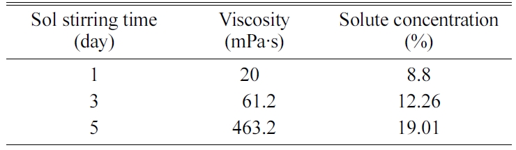
Table 1 shows the LCCC concentrations calculated based on
the weight loss after heat treatment at 1400 °C, and room temperature viscosity
after different mixing periods. When the synthesis time was extended from 1 d
to 5 d, there was a 20-fold increase in the viscosity from 20.1 to 463.2 mPa·s
and the LCCC concentration doubled from 9% to 19%. The increase in LCCC
concentration was attributed to the oxidation of ethylene glycol. Ethylene glycol
was transformed into oxalic acid and an esterification reaction occurred
between the oxalic acid and the remaining ethylene glycol; this reaction led to
volume reduction because of the dehydration of the solvent [10-11]. The
increased viscosity of the precursor solution resulted in a
continuous increase in the LCCC concentration, and the polymer chain
length also increased in accordance with the polymerization.
Plonczak et al. have previously reported that the
viscosity changes in ethylene glycol-based Ce0.9Gd0.1O1.95
as a function of time were a result of concentration changes occurring together
with the proceeding polymerization reaction [12].
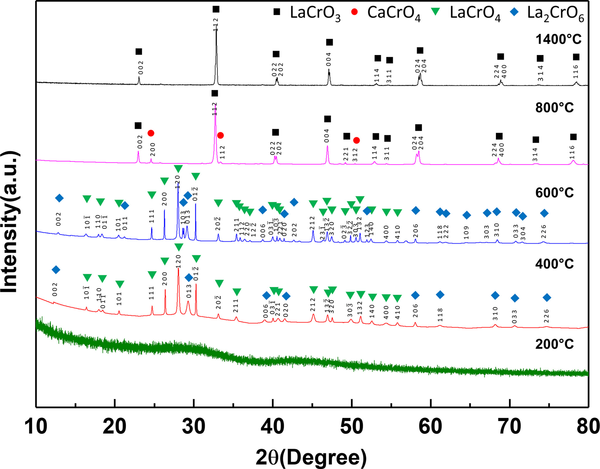
Fig. 2 shows the X-ray diffraction patterns of the LCCC
precursor heat-treated from 200 to 1,400 °C. No crystallization occurred
in the LCCC precursor that was heat-treated at 200 °C. The LCCC precursors
heat-treated at 400 and 600 °C contained LaCrO4 as the main
phase and La2CrO6 as a secondary phase. When the
LCCC precursor was heat-treated at 800 °C, CaCrO4
was observed as a secondary phase in addition to LaCrO3 as the main
phase. It was reported that LaCrO4 transforms into LaCrO3
at 700 °C [13] and the CaCrO4 secondary phase also forms in the
temperature range of 800-1,000 °C in Ca-doped LaCrO3 [13-15].
In the case of the LCCC precursor heat-treated at 1,400 °C, a single phase
of LaCrO3 was formed; the CaCrO4 phase had likely
dissolved into the LCCC lattice during heat treatment.
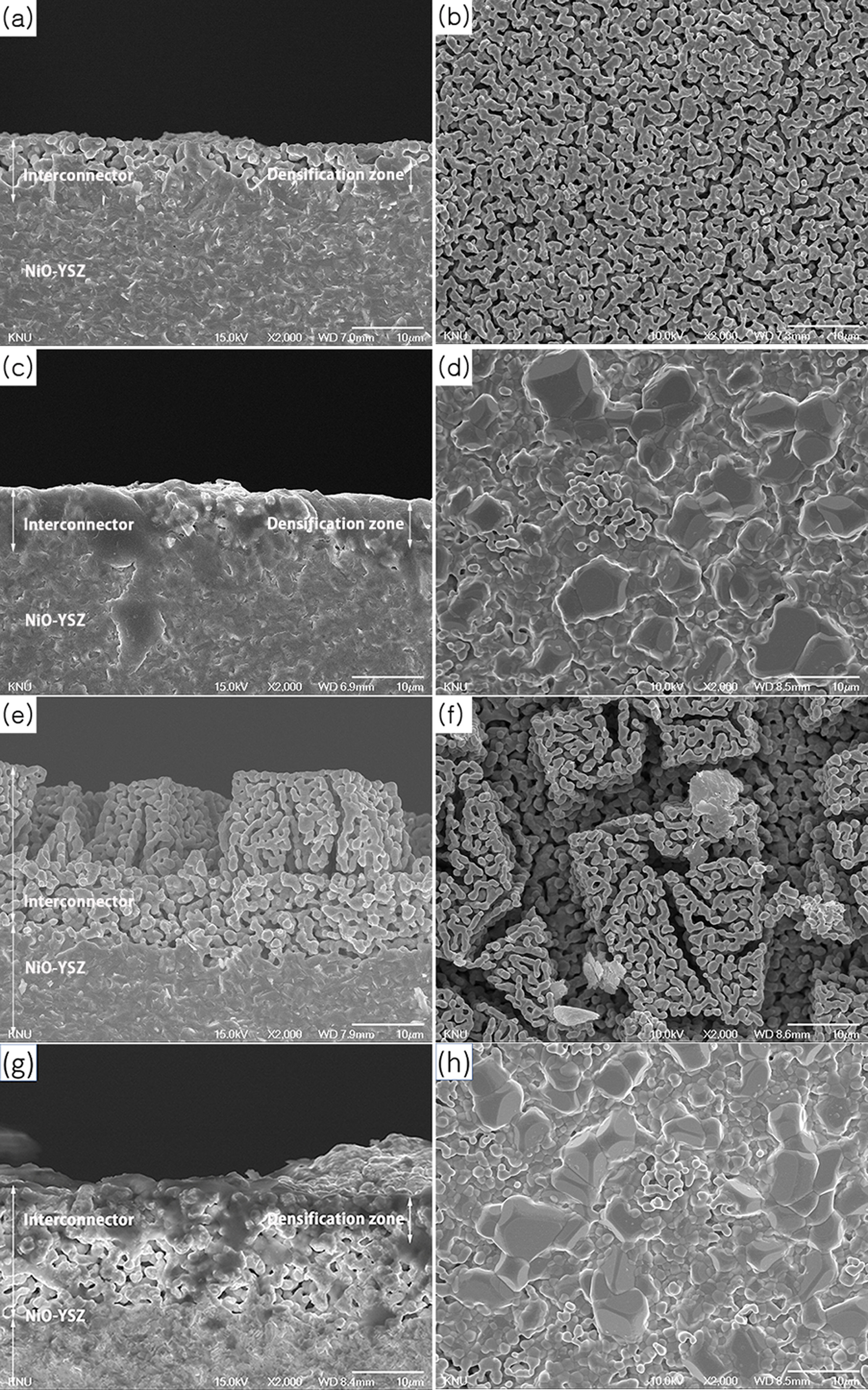
Fig. 3 presents the cross-section and top surface images
of the samples sintered at 1,400 °C for 2 h at heating rates
of 1 °C/min and 5 °C/min. Prior to sintering, each
precursor solution was screen-printed on the porous LCCC-YSZ layer as shown in
Fig. 1. Fig. 3(a) shows the microstructure of the specimen that was infiltrated
by the 9% LCCC precursor solution. It was found that the interconnector layer
was densified to half its depth. Fig. 3(c) shows the fully densified
microstructure of the specimen that was infiltrated by the 12% LCCC precursor
solution and the top surface shown in Fig. 3(d) is also very dense. Fig. 3(e)
shows the microstructure of the specimen infiltrated by the 19%
LCCC precursor solution. The interconnector layer had
a porous structure in this case because the precursor solution did
not infiltrate into the LCCC-YSZ layer as a result of its high viscosity.
Fig. 3(g) shows the microstructure of the specimen
infiltrated by the 12% LCCC precursor solution and heated at 1,400 °C with
a heating rate of 5 °C/min to slow down the gelation of the precursor
solution. The top layer was dense, but the bottom layer was porous. It was
rationalized that the differences in the viscosity and polymer molecular chain
length between the top and bottom layers of the interconnector could be
attributed to the rapid heating rate. The precursor on the top layer dried
faster when the heating rate is faster than slower. In addition, gelation
occurred continuously and larger clusters were formed via polymerization, a
result of the esterification reaction and evaporation of water during the
reaction that led to a higher solute concentration. Once the precursor solution
infiltrated the layers, the residual precursor solution could no longer
penetrate because of high viscosity and long polymer chain lengths.
The fully densified microstructure in Fig. 3(c) was a
result of the slow heating rate, which ensured the low viscosity and short
molecular chain length of the polymer. It was rationalized that the solution
present at the bottom of the sample would also move slightly upwards because of
the capillary force generated when the remaining precursor solution transformed
into the xerogel.
|
Fig. 1 Microstructures of the bilayers co-fired at 1,400 °C for 2 h: (a) cross-section and (b) top surface. |
|
Fig. 2 X-ray diffraction patterns of the precursor heat-treated at various temperatures. |
|
Fig. 3 Microstructures at the cross-section (left) and top surface (right). The layers were fired at 1,400 °C for 2 h at a heating rate of (a-f) 1 °C/min and (g-h) 5 °C/min. |
|
Table 1 LCCC concentration in the LCCC precursor annealed at 1,400 °C and room temperature viscosity as a function of the stirring time at 95 °C. |
Porous LCCC-YSZ (LCCC 70 wt.%−YSZ 30 wt.%) was
formed on a NiO-YSZ anode substrate and subsequently treated with
an ethylene glycol-based LCCC solution to enhance its density. At the heating
rate of 1 °C/min, the precursor solution with an LCCC concentration
of 12% permeated the entire interconnector layer. When
the heating rate was 5 °C/min, a dense region was formed at the top layer.
It is considered that the precursor solution remaining on the surface after
screen-printing had a higher viscosity and longer molecular length than that on
the bottom layer. The solution dried rapidly at the surface during the rapid
heating rate and further infiltration did not occur.
This work was supported by the Korea Institute of
Energy Technology Evaluation and Planning (KETEP) grant funded by the
Korea government (MOTIE) (2019-3010-0324-60, The development
of high-efficiency modular SOFC system with extensible
power generation).
- 1. W.Z. Zhu and S.C. Deevi, Mater. Sci. Eng. A 348 (2003) 227-243.
-

- 2. J. Molenda, K. Swierczek, and W. Zajac, J. Power Sources 173 (2007) 657-670.
-
- 3. B.K. Park, R.H. Song, S.B. Lee, T.H. Lim, S.J. Park, C.O. Park, and J.W. Lee, J. Kor. Ceram. Soc. 51 (2014) 231-242.
-
- 4. N.Q. Minh and T. Takahash, in “Science and technology of ceramic fuel cell, 1st Edition” (Elsevier Science, 1995).
-
- 5. S.C. Singhal and K. Kendall, in “High temperature and solid oxide fuel cells: Fundamentals, Design and Applications, 1st Edition” (Elsevier Science, 2004)
-
- 6. M. Mori and N.M. Sammes, Solid State Ionics 146 (2002) 301-312.
-
- 7. K. Deshpande, A. Mukasyan, and A. Varma, J. Am. Ceram. Soc. 86 (2003) 1149-1154.
-
- 8. J. Ovenstone, K.C. Chan, and C.B. Ponton, J. Mater. Sci. 37 (2002) 3315-3322.
-
- 9. H.C. Lee, B.K. Kang, J.H. Lee, Y.W. Heo, J.Y. Kim, and J.J. Kim, Ceram. Int. 39 (2013) 8737-8741.
-
- 10. E.A. Lee, S. Lee, H.J. Hwang, and J.W. Moon, J. Power Sources 157 (2006) 709-713.
-
- 11. E.A. Lee, J.S. Yoon, H.J Hwang, J.W. Moon, and N.U. Cho, J. Ceram. Process. Res 9 (2008) 538-543
- 12. P. Plonczak, M. Joost, J. Hjelm, and M. Søgaard, J. Power Sources 196 (2011) 1156-1162.
-
- 13. R. Koc and H.U. Anderson, J. Eur. Ceram. Soc. 9 (1992) 285-292.
-
- 14. G.M. Christie, P.H. Middleton, and B.C.H. Steele, J. Eur. Ceram. Soc. 14 (1994) 163-175.
-
- 15. H.C. Lee, B.K. Kang, J.H. Lee, Y.W. Heo, J.Y. Kim, and J.J. Kim, J. Kor. Ceram. Soc. 49 (2012) 197-203.
-
 This Article
-
2020; 21(2): 208-212
Published on Apr 30, 2020
- 10.36410/jcpr.2020.21.2.208
- Received on Nov 1, 2019
- Revised on Jan 10, 2020
- Accepted on Jan 17, 2020
Services
- Abstract
introduction
experimental
results and discussion
conclusions
- Acknowledgements
- References
- Full Text PDF
Shared
Correspondence to
- Joon-Hyung Lee and Jeong-Joo Kim
-
School of Materials Science and Engineering, Kyungpook National University, Daegu 41566, Republic of Korea
Tel.: +82–53–950–5635; Fax: +82–53–950–5645
Tel.: +82–53–950–7512; Fax: +82–53–950–5645 - E-mail: jjkim@knu.ac.kr, joonlee@knu.ac.kr
Clean-Energy Research Institute(CRI), Hanyang University, 222, Wangsimni-ro, Seongdong-gu, Seoul, 04763, Korea
E-mail: jcpr@hanyang.ac.kr