


- Mechanism of stopping crack propagation in continuous fiber reinforced self-healing ceramic
Jang-Won Leea, Ki-woo Namb and Wataru Nakaoa,*
aFaculty of Engineering, Yokohama National University, 79-5, Tokiwadai, Hodogaya-ku, Yokohama 240-8501, Japan
bDepartment of Materials Science and Engineering, Pukyong National University, 45 Yongso-ro, Nam-gu, Busan 48547, Korea
The self-healing fiber-reinforced
composite (abbreviation: shFRC) was made by adding SiC, a self-healing
material, between an Al2O3 matrix and an Al2O3
continuous fiber. shFRC has the characteristic of healing the reduced strength
by self-healing. The purpose of this study was to evaluate the damage and
healing of new composite material, shFRC, and define new failure criteria. The
test method used in this study was a high temperature creep test. The interface
fracture behavior with time was investigated by analyzing the creep rate. The
creep test conditions were 137 MPa and 150 MPa at 1,000 oC, and
68.5 MPa, 100 MPa, and 137 MPa at 1,200 oC, respectively. As a
result, the crack propagation of 1,000 oC was stopped by
healing, and the creep rate was zero. The crack healing part was higher than
the strength before the crack formation. Due to the rapid hardening of the
interface and the decrease in strength of the fiber, delayed fracture behavior
was not observed at 1,200 oC. If the crack is stopped by
self-healing at a constant load, shFRC can use that load stress as the
allowable stress. However, when the reaction rate of the interface is markedly
rapid, crack propagation is difficult to control.
Keywords: Damage and healing behavior, self-healing, Fiber reinforced ceramics, Crack branching, Creep test, Crack suppression
Ceramics have higher heat resistance and specific strength
than metals. If the nickel alloy, used in the turbine blades of an aircraft jet
engine, is replaced with ceramic, fuel efficiency would be
dramatically increased by non-cooling and weight reduction.
Improved fuel economy has the advantage in that CO2 gas emissions
are reduced, and the acceleration of global warming can be alleviated. However,
their safety is significantly lower in actual operating environments
because ceramics are brittle. Thus, it is not suitable as a
component for an aircraft requiring high reliability. Continuous Fiber
Reinforced Ceramic Matrix Composites (abbreviation: CFCC), represented by
ceramic composite materials, is attracting attention as a countermeasure to
compensate for these problems [1-4]. CFCC has the property in that fiber
absorbs energy when a crack propagates and induces delayed fracture [5-6].
However, there is high risk of a sharp decline in strength after cracking. As a
solution to this problem, we propose a method of adding self-healing to CFCC.
The healing effects of fiber reinforced composites with
self-healing have already been reported in various fields.
Ultra-high-performance fiber reinforced concrete (UHPFRC) have been reported to
recover most of the compressive strength damaged by air and hydration reaction
[7], and hollow fiber-reinforced polymer com- posites have
been reported to recover most of the bending strength lowered by UV
reaction [8]. In addition, it has been reported that the
mechanical and lifetime models of self-healing ceramic matrix composites are
presented, and that the coupling of mechanical and physicochemical mechanisms
should be considered as a key element for predicting self-healing behavior in
oxidizing environment [9]. However, no experimental cases of
self-healing fiber-reinforced composite ceramics have been
reported.
The interface control of CFCC plays a key role because the
bond strength between the fiber and matrix has a major influence on the
fracture strength and behavior [10, 11]. CFCC composite material in which
self-healing material is added to the interface layer facilitates
interface control by oxidation as well as heals the
cracks, thereby restoring the strength weakened after the cracking
to better than the strength before cracking. This new composite material is
called self-healing Fiber Reinforced Ceramics (shFRC). Since shFRC is designed
with the weakest part interface layer, cracks propagate along the interface
layer and healing is manifested by high temperatures after
crack propagation.
The purpose of this study was to secure the high
reliability required at the operating environment by evaluating the fracture
and healing behavior and to establish a new fracture standard for shFRC when damage
and recovery occur simultaneously at high tem-
peratures. High temperature creep tests were performed to
simultaneously produce damage (load) and healing (high temperature).
Spinel-structured γ-phase alumina fibers with high heat resistance, high
chemical stability, and low cost were used. And the α-phase alumina, which can
maintain high strength for a lengthy duration at high
temperature and has excellent chemical stability, was
used as a matrix [12, 13]. SiC, known for its strength recovery by
high temperature oxidation, was used as the interface
layer between the matrix and fiber [14-17].
Specimen
The test specimen is an Al2O3f/SiC/Al2O3
composite containing non-oxide SiC in the interface layer of the fiber/matrix.
Continuous fibers (S-640D, γ-phase, Nitivy Co., Ltd.,
Tokyo, Japan) use bundles of twisted bundles of approximately 640 fibers with a
fiber diameter of 7 μm, and the composition is Al2O3 72%,
SiO2 28%. As the matrix (AKP-50, α-phase, Sumitomo Chemical Co.,
Ltd., Tokyo, Japan, Purity over 99.99%), an Al2O3 powder
having an average particle diameter of 0.23 μm is used. The powder used for the
interface layer is SiC (Ultrafine grade, β-phase, Ibiden Co., Ltd., Gifu,
Japan, Purity over 98%) having an average particle diameter of approximately
0.35 μm. The manufacture method used filament winding method to easily control
the thickness of the interface layer and the matrix. The slurry was mixed with
each powder (Al2O3, SiC) with distilled water, a
dispersant (Ammonium poly acrylate, A-30SL, TOAGOSEI CO., LTD., Japan) and a
binder (Acrylic emulsion, #7110, SEKISUI CHEMICAL CO., LTD., Japan) was added
and ball milled for 24 h to complete. Al2O3 continuous
fibers were impregnated into the Al2O3
slurry, and then coated by passing through the drying
furnace with 850 rpm at 90 °C, and the sample was obtained by repeating
the filament winding process three times under the same conditions. The
obtained sample was impregnated on the SiC slurry by the same
methods above with 650 rpm. Sample coated up to SiC was impregnated in Al2O3
slurry and forming on the 60 mm × 60 mm wide plates without drying. The formed
specimen was dried for 48 h at a pressure of 5 MPa. the obtained forming was
heated at 300 oC for five hours to remove dispersant and
binder, and then sintered at 1300 oC
for 10 h. Sintering atmosphere is Ar. The size of the processed specimen is
8.00 mm × 50.00 mm × 1.65 mm and the diameter of the center hole
is 4 mm. The interface layer is designed to be the weakest part. The thickness
of the interface layer coated on the fiber is approximately 14 μm and the
spacing between the fiber bundles is about 300 μm. The average diameter of the
fiber bundles is 200 μm. And the average density of the specimen is 2.3 g/cm3.
The test specimen contains
approximately 60 Vol.% of fiber, 9
Vol.% of interfacial layer, and 31 Vol.% of parent metal. Also, fiber
orientation is one axis. Fig. 2 shows the internal structure of the completed
test specimen.
Experimental
set-up
When the ratio 2ρ/2b of the diameter of the hole to the
width of the specimen is less than 0.5, the Howland method is regarded as
highly accurate [18]. Since 2ρ/2b is 0.5 in the specimen, the
stress concentration coefficient was
calculated using Equation (1) proposed by Howland.
Wherein ρ (mm) is the radius of the hole, b (mm) is half
the width of the specimen, and α is the stress concentration coefficient. The
test apparatus used a universal testing machine (EHF-FB5KN, SHIMADZU CO., LTD.,
Japan) which can control a crosshead and a load by the lower hydraulic pump.
The heating rate and the crosshead speed were set to 10oC/minute and
10 N/second with reference to JIS R1723:2015 standard, respectively.
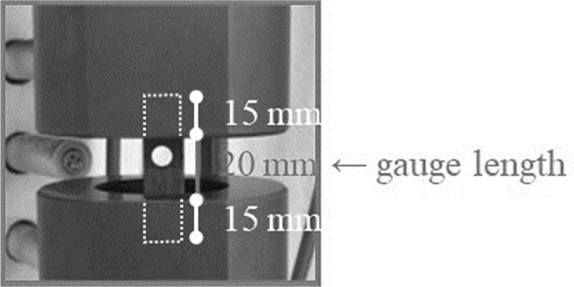
The jig was manufactured using SiC having a
relatively low thermal expansion rate even at high temperatures. The gauge
length of the test specimen was 20 mm, and the strain was calculated to use the
gauge length. The maximum stress was calculated by equations (2) and (3)
considering stress concentrations.
Wherein A (mm2) is the cross-sectional area, P
(N) is the load, σ0 (MPa) is the load per unit area, and σmax
(MPa) is the maximum normal stress to which the stress concentration factor is
applied. The stress used in the test data was σmax (MPa), and the
cross-sectional area A was calculated by subtracting the diameter of the hole 4
mm since it was calculated in the region where stress concentration occurred.
Fig. 3 shows the mounting of the specimen.
High temperature tensile test to determine creep
stress conditions
A high temperature tensile test was performed to determine
creep stress conditions. In the fiber reinforced composite
ceramics, the internal structure was not uniform due to internal defects and
voids during the compounding and sintering process. Thus, the average value
of tensile failure stress was calculated by performing the tensile
test three times [19, 20]. The temperature condition was set at 1,000 oC,
which is relatively slow, and 1,200 oC, which
is rapidly accelerating, considering the healing reaction rate of
SiC at atmospheric pressure in the air [21]. The heating rate and
the crosshead speed were 10 oC/minute and 0.5 mm/minute, respectively, referring to the standards of JIS R 1687: 2009.
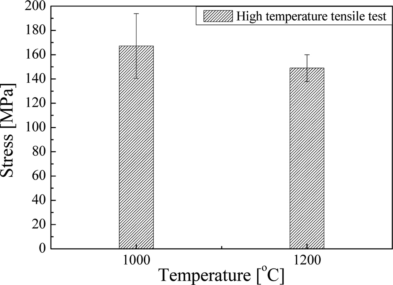
The results of the high temperature tensile test are shown in Fig. 4. Tensile
fracture stress at 1,000 oC was 147.9 MPa, 197.6 MPa, and 156
MPa, respectively and the average fracture stress was 167 MPa. Tensile fracture
stress at 1,200 oC was 161.7 MPa, 143.2 MPa, and 142 MPa,
respectively and the average fracture stress was 148 MPa. The temperature
conditions of the high temperature creep test were determined by the average
tensile stress. Creep stress conditions are 150 MPa, and 137 MPa respectively
at 1,000 °C. and 137 MPa, 100 MPa, and 68.5 MPa, respectively at 1,200°C. Fig. 1
|
Fig. 1 The manufacturing process of specimen. |
|
Fig. 2 Completed actual structure of self-healing fiber reinforced ceramics (by digital microscope). |
|
Fig. 3 Mounting of the test specimen. |
|
Fig. 4 High tensile strength at 1,000 oC, and 1,200 oC, respectively. |
Effect
of competition between damage and recovery on crack branching behavior
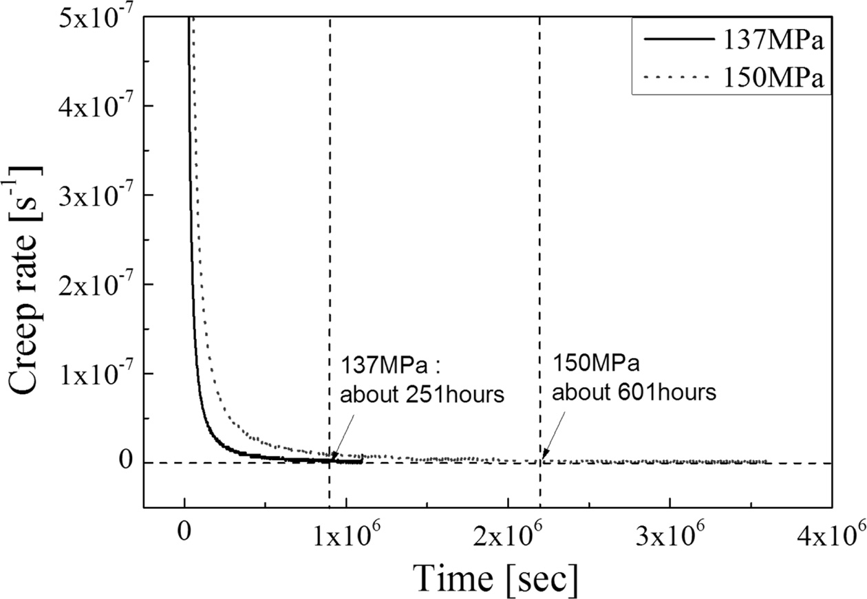
The creep test results at 1,000 oC are
shown in Fig. 5. Both creep rates converged to zero at the conditions of 150
MPa and 137 MPa, respectively. The creep rate converged to zero was 601 h at
150 MPa and 251 h at 137 MPa, respectively. From the fact that the creep rate
converges to 0, it can be observed that the crack propagation is suppressed by
the self-healing effect even though it is continuously damaged by the external
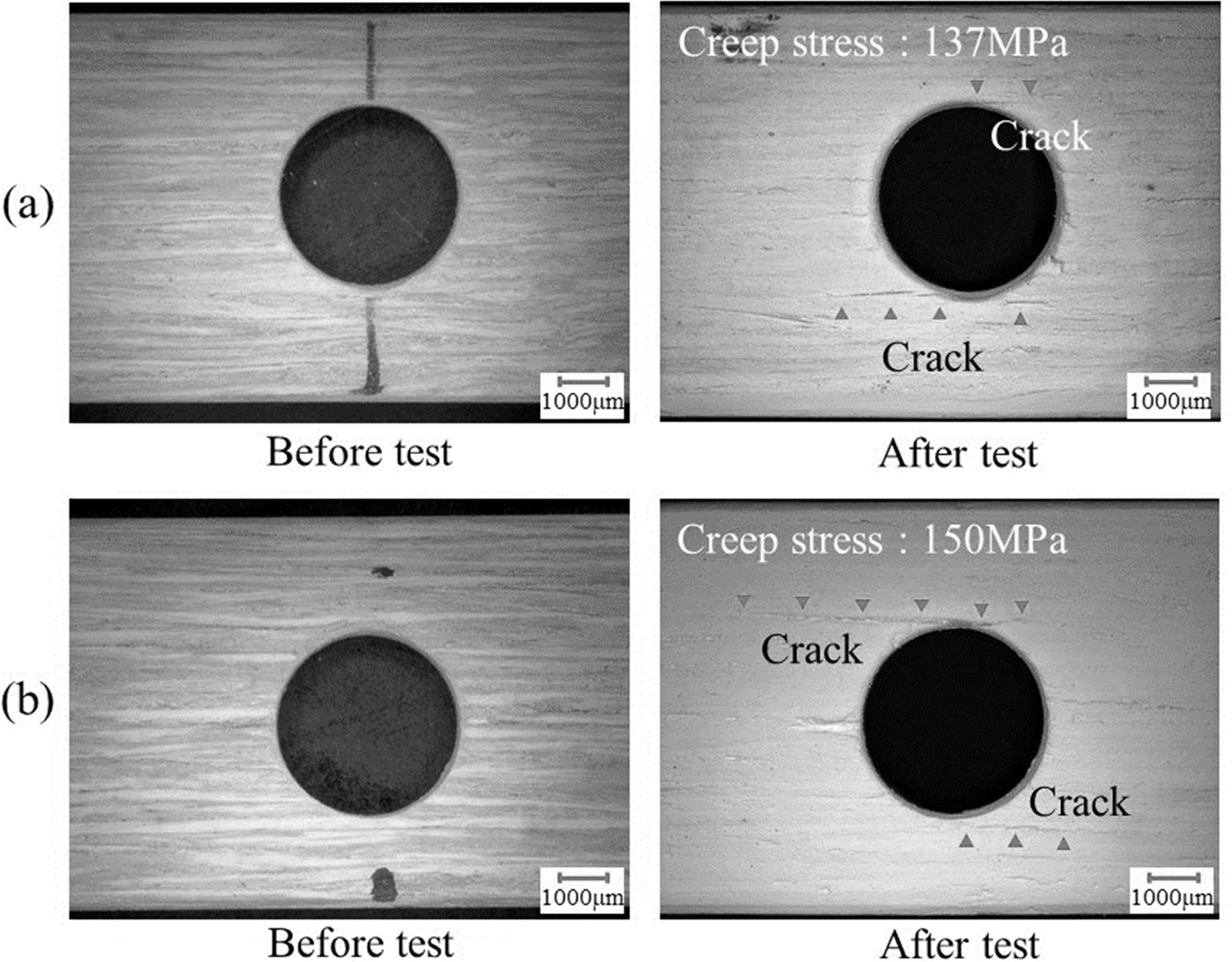
force. Fig. 6 shows the observation of the surface before and after each test
specimen. After the test of Fig. 6(a) and Fig. 6(b), the crack healed on the
surface of the specimen was observed. The crack healing length in Fig. 6(a) was
shorter than the crack healing length in Fig. 6(b). It can be observed that the
crack propagation length depends on the stress and the crack healing length
depends on the time when the creep rate converges to zero.
Strength
recovery effect by self-healing
Ozaki et al. set the standard for self-healing that the
strength of the healed part should be equal to or higher than the strength
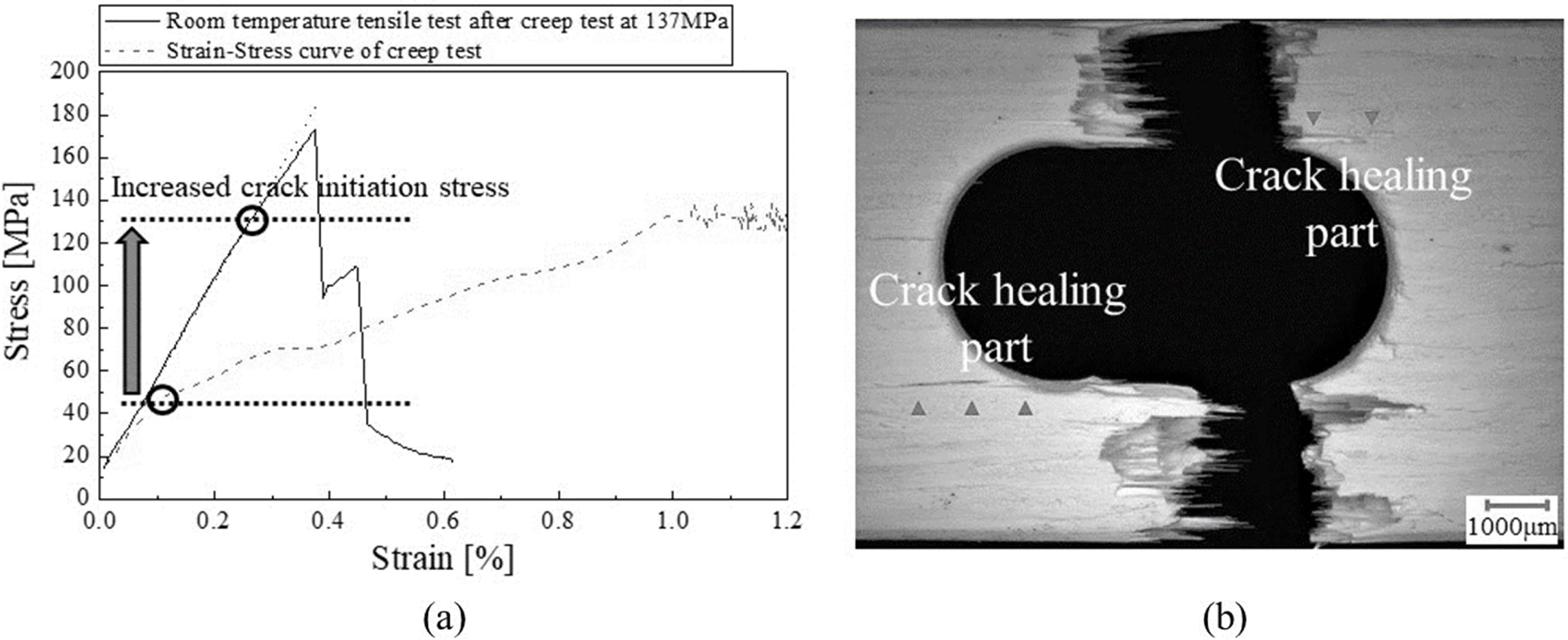
before the crack began [22]. Tensile tests were performed at room temperature
on the specimens conducted at a stress of 137 MPa, and the results are shown in
Fig. 7. Fig. 7(a) shows the stress rise section of the creep test and the
stress-strain curve at room temperature tensile test. The crack initiation
stress and strain increased. However, the slope after cracking was higher than
that before the test. It is considered that this is because the crack branching
at the weakest interface is made difficult by the self-healing
reaction of the interface layer. Fig. 7(b) shows a photograph
of the surface fractured by room temperature tension. The
specimen was last fractured but no more cracks propagated at the healed crack
part. This is because the interfacial layer designed with the weakest part
designed was cured by high temperature oxidation in the process of healing the
crack.
From the results in Fig. 7, it can be observed that the
ductility is lowered and the fracture toughness and crack
initiation stress are increased by interfacial curing. Additionally,
the reduced strength after the initiation of the crack is recovered by
self-healing, it was confirmed macroscopically that the
crack no longer occurs in the healing part even when the fracture stress is
loaded.
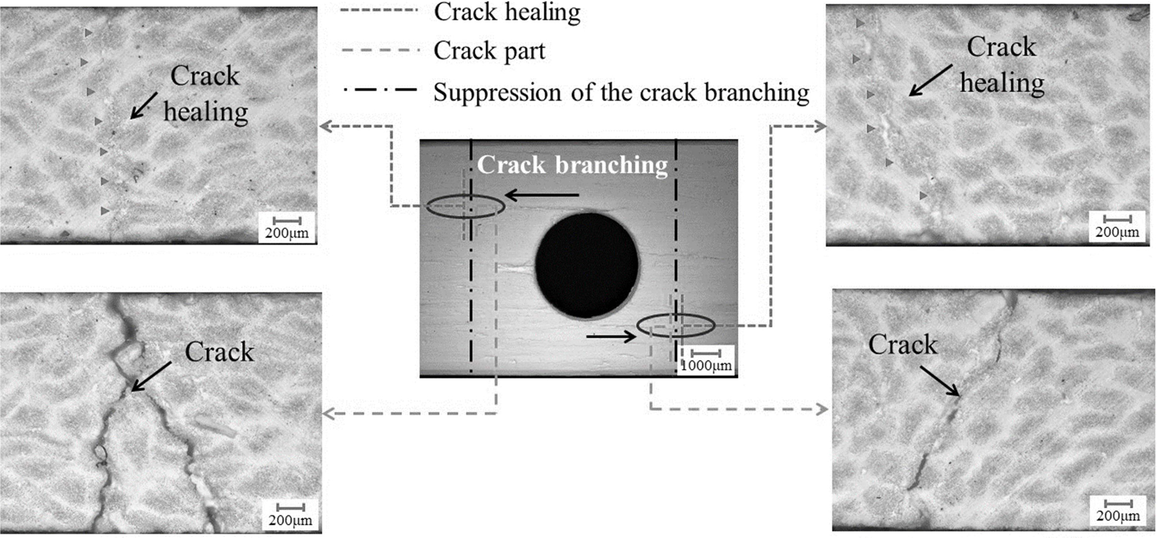
Fig. 8 shows an internal cross-sectional picture of
stopped crack part after the high temperature creep test at 150 MPa. The part
where the crack propagation stopped was confirmed macroscopically. It can be
observed that at 150 MPa, the crack did not propagate again for 400 h after 601
h when the crack propagation stopped. In other words, it is suggested that the
constant load stress at which the crack is stopped by self-healing can be
designed to the allowable stress.
Effect
of oxidation of interface layer on fracture behavior
Because of the hardening by oxidation of the interface
layer, cracks become markedly difficult to propagate to the interface layer and
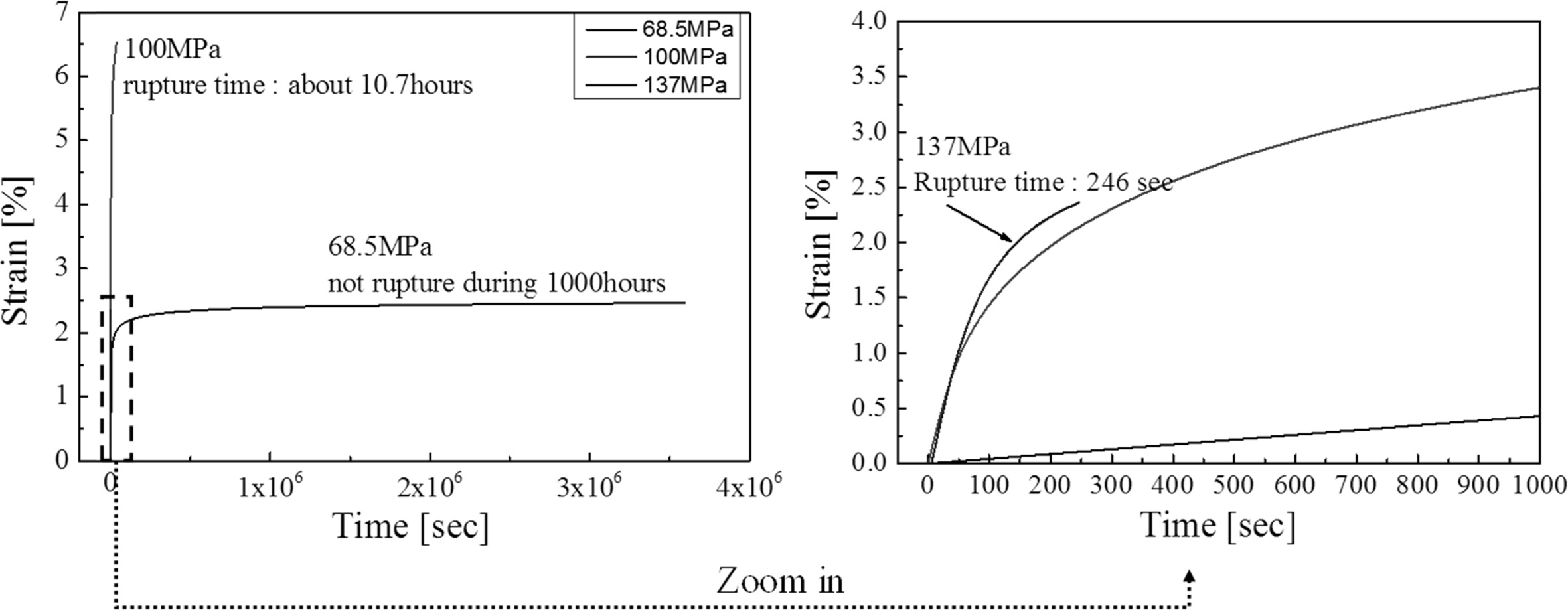
most of the load is applied to the fibers. The creep tests were performed at
1,200 °C to investigate the influence of fracture behavior due to rapid
oxidation of the interfacial layer. Fig. 9 shows creep curves at 68.5 MPa, 100
MPa, and 137 MPa, respectively. The fractured time at 100 MPa was 10.7 h, and
the fractured time at 137 MPa was 246 seconds. In contrast, 68.5 MPa was not
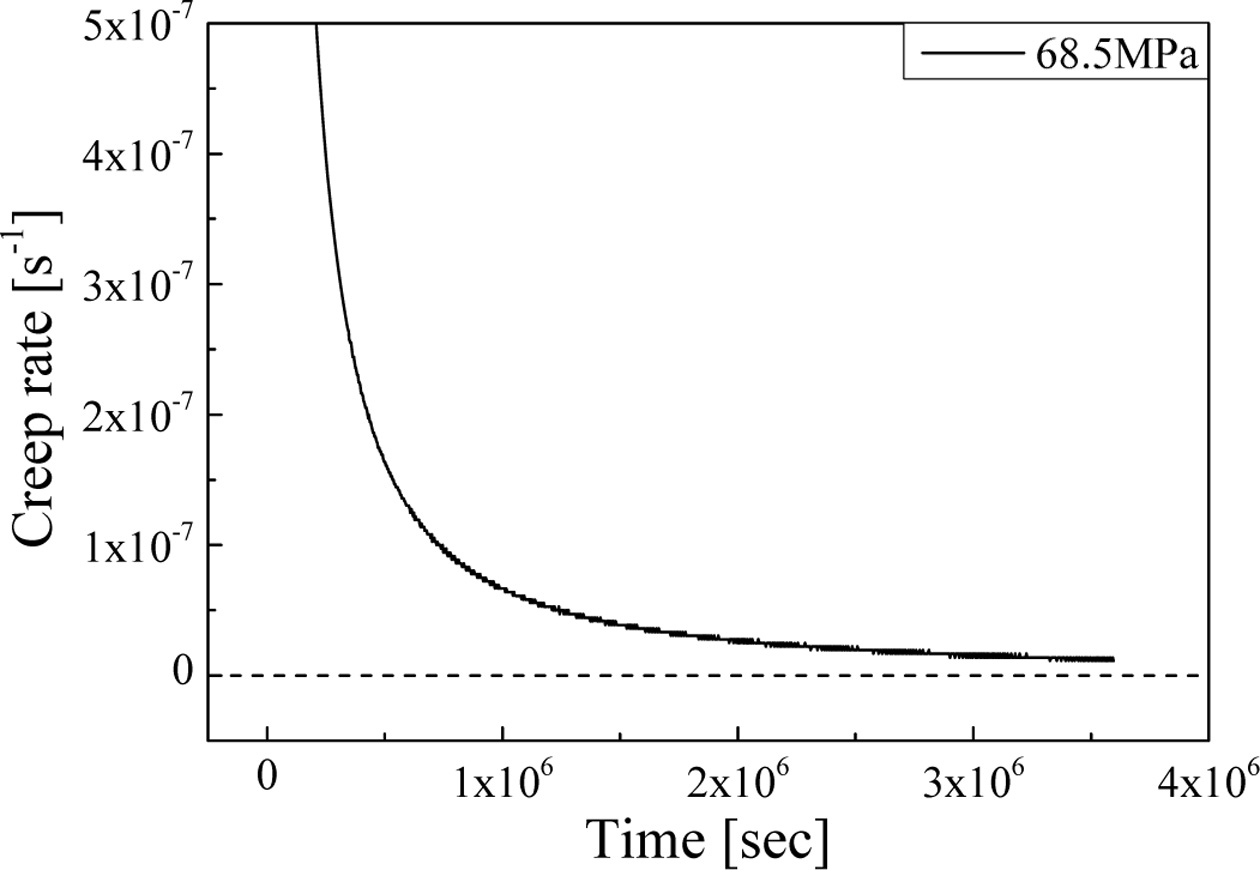
fractured for 1,000 h. Fig. 10 shows the time-creep rate curves for the creep tests conducted at 68.5 MPa. Fig. 10
shows the time-creep rate curves for the creep tests conducted at 68.5
MPa. Unlike the test results performed at 1,000 °C, the creep rate did not
converge to zero for 1,000 h. However, it was confirmed that the creep rate continuously slowed. This is because interface
hardening occurred by rapid oxidation before the crack propagated along the
interface layer by the hardened interface.
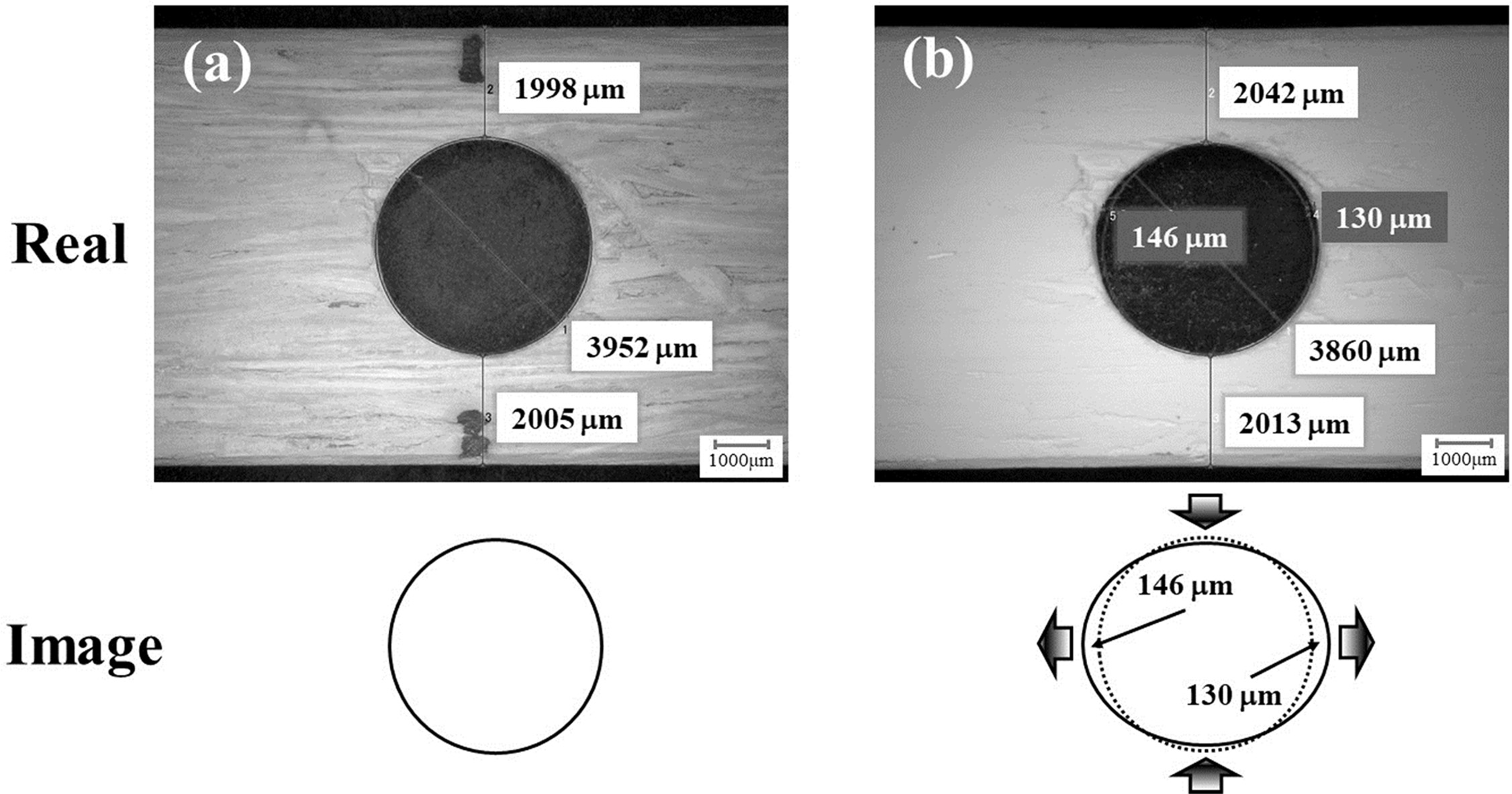
Fig. 11 shows the surface photographs of before the test
and after the test of the specimens performed at 1,000 h 68.5 MPa. No crack was
observed on the surface after the test, but it was confirmed that the hole was
extended by approximately 0.2 mm in the load direction. The matrix exhibits
Nabarro-Herring creep behavior in which atoms are diffused by prolonged
high-temperature exposure at relatively low stress, and reinforcing fibers (γ-phase)
are expected to drastically decrease in strength due to grain
growth as the amorphous phase is transferred to the α-phase
[23]. For this reason, it is thought that the fiber existing inside the test
piece first fractured due to the decrease in strength of the fiber.
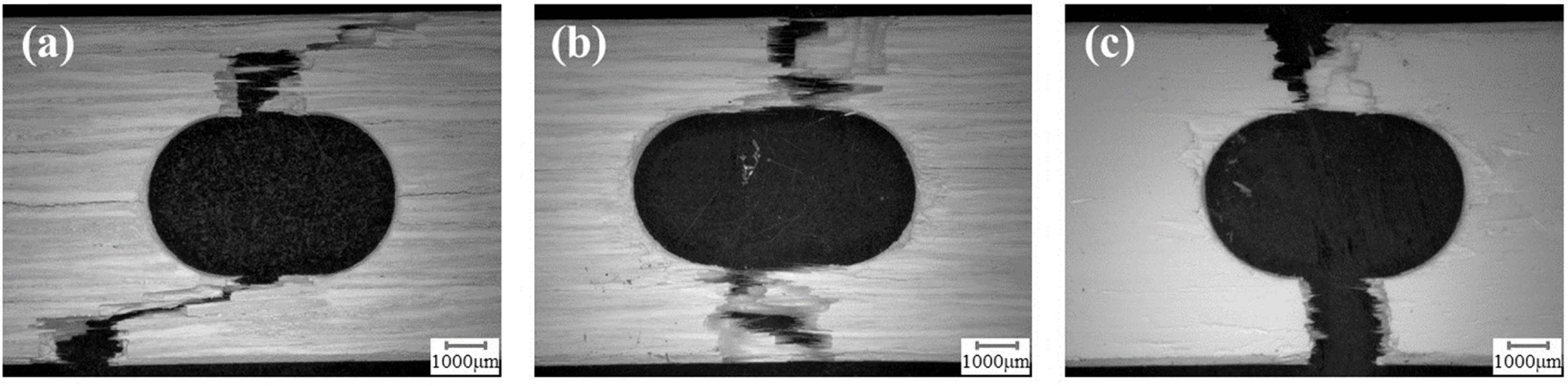
Fig. 12(a) and 12(b) show creep fracture surfaces of 137
MPa and 100 MPa, respectively. Fig. 12(c) shows the room temperature tensile
fracture surface of a specimen subjected to creep test at 68.5 MPa for 1,000 h.
It was confirmed that most of the interface layer was oxidized and the entire surface
was white. Oriented fibers are not observed due to the thick oxide layer on the
surface. This is because all of the SiC introduced into the interface layer was
oxidized to SiO2. And the pull-out length of the fiber is markedly
short, and almost no interface fracture occurs compared to Fig. 12(a) and Fig.
12(b). From the surface observation results, it has become clear that the
above-mentioned decrease in strength of the fibers and the diffusion
creep behavior of the base material appeared. Therefore, it is
difficult to expect the delayed fracture by the fiber at 1,200 oC.
|
Fig. 5 Creep rate curve of the shFRC at 1,000 °C. |
|
Fig. 6 Picture of specimen surface before and after the creep test (a) 137 MPa, (b) 150 MPa. |
|
Fig. 7 (a) Comparative analysis of crack initiation stress before and after the creep test at 137 MPa, (b) Tensile fracture behavior observation after creep test. |
|
Fig. 8 Internal cross section of test specimen for 1,000 h at 1,000 oC, 150 MPa. |
|
Fig. 9 Time-strain curve of the shFRC at 68.5 MPa, 100 MPa, and 137 MPa, respectively. |
|
Fig. 10 Time-creep rate curve at 68.5 MPa, 1,000 h. |
|
Fig. 11 Surface of the specimen of 68.5 MPa, 1,000 h condition (a) before the test (b) after the test. |
|
Fig. 12 Tensile fracture surface with stress condition (a) at 137 MPa, (b) at 100 MPa, (c) Tensile fracture surface of the specimen after the test at 68.5 MPa for 1,000 h. |
In this study, we evaluated the crack propagation behavior
when Al2O3/SiC/Al2O3f damage and
healing behavior occurred simultaneously. The results are as follow.
In the 1,000 oC creep test, the time when
the creep rate
converged to zero was 601 h at 150 MPa and 251 h at 137 MPa, respectively. The
higher the load stress, the longer the propagated crack length. Therefore, the
crack propagation length of Al2O3/SiC/Al2O3f
depends on the stress and the crack healing length depends on the time when the
creep rate converges to zero.
Since Al2O3/SiC/Al2O3f
makes it difficult to crack at the weakest interface layer by the self-healing
reaction of the interface layer at 1,000 oC, the
fracture toughness and the crack initiation stress increases.
At
1,000oC, when crack propagation is suppressed at a constant load and
completely stops, cracks no longer propagates. Thus, it is suggested that creep
stress higher than the crack initiation stress can be an allowable stress.
When the oxidation reaction rate of the interfacial layer
is markedly rapid and the load stress is low (1,200 oC, 68.5
MPa), the matrix shows diffusion creep behavior and the fiber shows a sharp
decrease in strength due to phase transformation. And the
interfacial layer makes it difficult for cracks propagation since all
SiC is oxidized to SiO2 before cracks are initiated. Thus,
the fiber is first fracture inside. In this reason, it is difficult
to expect a delayed fracture by fiber reinforcement.
At
1200 oC, stopping and suppression of crack pro-
pagation is no observed, but at 1,000 oC, a behavior is
confirmed in which damage and healing occur simulta- neously. Therefore, the suitable
operating temperature of Al2O3/SiC/Al2O3f
is 1,000oC.
This work has been supported
by the Advanced Low Carbon Technology Research and
Development Program (ALCA), JST, Japan
- 1. L. Li, Mater Sci Eng, A, 695 (2017) 221-229.
-

- 2. L. Li, Compos B Eng, 66 (2014) 466-474.
-
- 3. N. Bansal and J. Lamon, Eds., in ”Ceramic Matrix Composites: Materials, Modeling, Technology, and Applications” (Wiley, 2013) p.217-234.
-
- 4. I.M. Low, Eds., in “Ceramic Matrix Composites: Microstructure, Properties and Applications” (Woodhead Publishing Limited, 2006) p.339-341.
-
- 5. H.H. Moeller, W.G. Long, A.J. Caputo, and R.A. Lowden, Ceram. Eng. Sci. Proc. 8 (1987) 977-984.
-
- 6. T. Fett, D. Munz, R.D. Geraghty, and K.W. White, Eng. Fract Mech 66 (2000) 375.
-
- 7. S. Kim, D.-Y. Yoo, and M.-J. Kim, Nemkumar Banthia, Cem. Concr. Compos. 104 (2019) 103335.
-
- 8. J.W.C. Pang and I.P. Bond, Compos. Sci. Technol. 65 (2005) 1791-1799.
-
- 9. C. Cluzel, E. Baranger, P. Ladevezèze, and A. Mouret, Composites, Part A 40[8] (2009) 976-984.
-
- 10. J. Lamon, in “Ceramic Matrix Composites: Materials, Modeling and Technology” (Wiley, 2014) p.40-64.
-
- 11. R.W. Rice, in Proceedings of the 5th Annual Conference on Composites and Advanced Ceramic Materials: Ceramic Engineering and Science Proceedings, Vol. 2, January 1981, edited by J.S. William (The American Ceramic Society, 1981) p. 661-701.
-
- 12. H. Li and H.X. Lu, S. Wang. Ceram. Int. 35 (2009) 901-904.
-
- 13. R. Bharthasaradhi and L.C Nehru. Phase Transitions. 89[1] (2016) 77-83.
-
- 14. K. Ando, T. Ikeda, S. Sato, F. Yao, and Y. Kobayasi, Fatigue Fract. Eng. Mater. Struct. 21 (1998) 119-122.
-
- 15. K. Ando, B.S. Kim, M.C. Chu, S. Saito, and K. Takahashi, Fatigue Fract. Eng. Mater. Struct. 27 (2004) 533-541.
-
- 16. W. Nakao, K. Takahashi, and K. Ando, Mater. Lett. 61 (2007) 2711-2713.
-
- 17. T. Osada, W. Nakao, K. Takahashi, and K. Ando, J. Am. Ceram. Soc. 92 (2009) 864-869.
-
- 18. R.C.J. Howland, Trans. Roy. Soc. 229 (1930) 48-86.
-
- 19. W. König, Ch Wulf, P. Graß, and H. Willerscheid, Manuf. Technol. 34 (1985) 537-548.
-
- 20. R. Komanduri, Mach. Sci. Technol. 1 (1997) 113-152.
-
- 21. T. Osada, W. Nakao, and K. Ando, J. Am. Ceram. Soc. 92 (2009) 864-869.
-
- 22. S. Ozaki, T. Osada, and W. Nakao, Int. J. Solids Struct. 100-101 (2016) 307-318.
-
- 23. A.R. Bunsell and M.-H. Berger, in “Fine Ceramic Fibers” (Marcel Dekker, Inc., 1999).
 This Article
-
2020; 21(2): 200-207
Published on Apr 30, 2020
- 10.36410/jcpr.2020.21.2.200
- Received on Oct 10, 2019
- Revised on Jan 8, 2020
- Accepted on Jan 17, 2020
Services
- Abstract
introduction
test methods
results and discussion
conclusion
- Acknowledgements
- References
- Full Text PDF
Shared
Correspondence to
- Wataru Nakao
-
Faculty of Engineering, Yokohama National University, 79-5, Tokiwadai, Hodogaya-ku, Yokohama 240-8501, Japan
Tel : +81-45-339-4016 Fax: +81-45-339-4016 - E-mail: Nakao-wataru-hy@ynu.ac.jp
Clean-Energy Research Institute(CRI), Hanyang University, 222, Wangsimni-ro, Seongdong-gu, Seoul, 04763, Korea
E-mail: jcpr@hanyang.ac.kr