


- Carbon nanotube-biomorphic composites and filter application: A Review
Jung Gyu Parka, Se Young Kimb, In Sub Hanb and Ik Jin Kima,*
aInstitute for Processing and Application of Inorganic Materials, (PAIM), Department of Materials Science and Engineering, Hanseo University, 46, Hanseo 1-ro, Haemi-myun, Seosan-si, Chungnam, 31962, Korea
bKorea Institute of Energy Research (KIER), 152, Gajeong-gu, Daejeon, 34129, Korea
As interest in environmental
pollution has increased, research in the field of filtration has been
concentrated. While various types of filters have been developed, research on
nanomaterial filtration has been limited. Since then, the development of new
materials such as carbon nanotubes (CNTs) has accelerated the study of new
filters. Especially, CNTs have been among the most attractive materials ever
synthesized for the development of nano-technologies. However, there are fundamental
technical problems to be solved the development of new CNT composites. One of
these problems is the development of a CNTs filter with excellent adsorption
behavior and a filter that is capable of filtering a specific substance. In
addition, it is necessary to develop a technology to increase the uniform
distribution of CNTs, and to reduce the high processing cost of CNT composite
production. In general, the chemical pathways for the production of CNTs
include hydrocarbon gases, such as methane (CH4) and acetylene (C2H2),
through metal nanoparticle catalysts. However, nano-metal particles have a
strong coagulation phenomenon at high temperature by catalytic chemical vapor
deposition (CCVD) method. In this review, attempts were made by applying three
different reaction techniques to form CNTs on biomorphic carbon materials (BCM)
coated with catalyst materials to control the shape and size of CNTs.
Hierarchical carbon substrates with pore size of 100 ~ 300 μm were
developed using carbonization reaction. Linde type A (LTA) zeolite,
silicalite-1, and mesoporous SiO2 template crystals were
simultaneously synthesized and coated on the BCM by an in-situ
hydrothermal process to synthesize high-yield CNTs composites.
Keywords: Carbon nanotubes, Template, Biomorphic carbon materials, Catalytic chemical vapor deposition, Nanofilters
Recently, there has been increased interest in approaches
used for the production of various hierarchical and complex
microstructures with biodiversity-carbon materials with natural
biological substances, such as wood [1], rattan [2], or rice husk [3] used as a
template. Of these, natural trees have received considerable attention, as
their cell structure is so large that their tissue structure is converted into
a template material [4, 5]. Biomorphic materials with unique and elaborate
structures can be obtained by the pyrolysis of tree varieties such as Chamaecyparis
obtusa (Cypress, a.k.a. Hinoki), Pinus resinosa,
and Picea [6], resulting in carbonaceous forms. This form
produces a steel and ceramic mold complex that can penetrate and react with
coated oxides and non-oxides to be used in a wide range of applications, such
as filtration and catalysts for potentially powerful technical applications.
Because of the wide range of applications, it is very important to produce
sufficient quantities of well-defined and organized carbon nanotube
(CNT) arrays at low cost [7, 8].
Recent reports of CNT composites research of medical,
energy storage, and filtration applications [9-12] due to their morphological,
physical, and chemical properties have been published [13, 14]. The high
efficiency of CNT in filtration can be explained by observing the structure in
which high surface area and large aspect ratio lead to the formation of strong
Van der Waals forces between individual CNTs. This is because the microbial
cytotoxicity of CNTs partially affects the filtration performance, which has a
larger pore size that can fix contaminants, including bacteria and viruses, in
flocculation and interstitial pore spaces [15, 16]. The use of such
nanomaterials embedded in membranes or other structural media has been
considered an effective method for more approaches than just water treatment.
The dense CNTs network, which forms a variety of pore sizes from micropores to
medium pores supported on ceramic substrates, can be used to
physical adsorbents for removing contaminants [17], which make them
advantageous for filters in gas adsorption, and water filtration and
purification systems [18-20] Other applications include
hydrocarbon separation [21], and polluted air filters [22].
All these characteristics provide fundamentally different opportunities
for the development of new CNT-containing composites
however, several technical challenges were remained. One
of them is a CNT oil filter with excellent adsorption
behavior, and a suitable filter to convert it to a filter that is suitable for
a specific application. In addition, the producing of CNTs
composites has a number of technical problems that need to
be addressed. These include the potential damage to CNTs in the substrate; it
has been found to be an important and difficult challenge
to obtain a uniform and un-agglomerated distribution of CNTs in
the matrix, also is the high cost of processes associated
with CNTs and their composites.
The chemical pathway for CNTs production is the
decomposition of hydrocarbon gases through metal nanoparticle catalysis using
metals such as cobalt (Co), iron (Fe), nickel (Ni), and copper
(Cu). However, as the CNTs size decreases to nanoscale,
the metal particles agglomerate strongly during the synthesis of CNTs at high temperatures.
Thus, with respect to template-coated porous ceramics and nanostructured
biomorphic carbon materials (BCM), it is desirable to maintain the shape
and size of the CNTs at chemical vapor deposition (CVD)
treatment temperatures of 650 ~ 750 oC, as they are
required to homogeneously penetrate carbon sources like methane
(CH4) and acetylene (C2H2) [23-25].
Generally, matrices or catalyst supports such as alumina
[26], mesoporous silica [27], and zeolite [28], have been used to prevent the
agglomeration of the catalyst nanoparticles. Among them, zeolites are
considered an excellent template for the support or encapsulation of catalyst
nanoparticles, because of their well-defined pore
structure, and high surface area [29], thereby leading to a catalyst-particle
stabilization, the production of a fine dispersion of nanoparticles, and the
increase of the number of nucleation sites, which is advantageous for
high-yield CNTs synthesis [30, 31].
This review summarizes the formation of CNTs in a template
coated BCM using the catalytic chemical vapor deposition (CCVD) method. The
synthesis was carried out with the application of a three-step
processing route for CNTs composites. First, a BCM was produced
by a carbonizing reaction. Secondly, the templates were synthesized within and
coated simultaneously on the carbon template using the in-situ method
and wet process. The BCM was then subjected to a wetting process that resulted
in the formation of a metal-ion loaded template; and finally, the
CNTs were synthesized using the CCVD method.
In the mid-1980s, Kroto et al. (1996 Nobel Prize in
Chemistry) discovered a new closed carbon form that consisted of
hexagonal and pentagonal faces (buckminster-fullerene-C60). Most
notable is the discovery of one-dimensional (1D) CNTs and two-dimensional (2D) single atomic layer carbon, graphene (Nobel Prize
2010) [32]. An important feature of
this carbon material has attracted a large number of researchers to explore its
unique properties for various engineering topics, and to develop new
applications. CNTs was first discovered by Dr. Sumio Iijima as a needle-shaped
tube composed of “coaxial tubes of graphite sheets” and has been cited more
than 10,000 times in almost all articles on CNTs to date [33].
Types
of carbon nanotubes
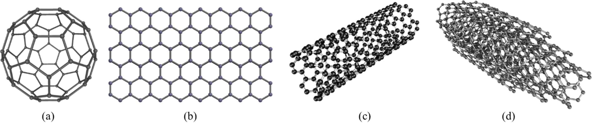
The ability to combine in different ways is a unique
feature of carbon that creates multiple homogeneous forms. If the four atoms of
the carbon atom are equally shared (sp3 hybridization), a diamond
will form Fig. 1. Graphite can be changed from diamond to diamond, and from
fullerene to CNTs and graphene. When three electrons are shared in one plane
and the fourth electron is localized (sp2 hybridization) between all
the atoms, graphite is formed [34, 35]. This type of bond shows a very strong
bond; but in graphite, the graphene layer is weak, with van der Waals bond.
Carbon, also called fullerene, is another overlapping graphene sheet of sp2-bonded
carbon atoms Fig. 1(b). These nanotubes are
concentric graphitic cylinders capped at either end by a half fullerene, owing
to the presence of five membered rings. Depending on the number of
carbon sheets, these nanotubes can be classified into two types: single-walled
CNTs (SWCNTs) and multi-walled CNTs (MWCNTs) with double-walled CNTs (MWCNTs),
as shown in Figs. 1(c) and (d).
SWCNTs have a small diameter of 0.4 ~ 4 nm and
exhibit a certain property that can be metallic or semi-conducting,
depending on their chirality [36]. On average, without
chirality control, one-third of metallic and two-thirds of semi-conducting
SWCNTs can be obtained. A SWCNTs is considered perfectly crystalline, that is
defect-free, if the grapheme sheet has no variations in the
hexagonal aromatic structure of the carbon atoms [37].
MWCNTs can be visualized as concentric SWCNTs, which have
several walls ranging from two to less than a hundred,
leading to the diameter of a MWCNT ranging from 1 nm,
and rarely reaching over 100 nm. In MWCNTs, the general innertube distance is
0.34 nm, which is the same distance as that between two parallel graphene
sheets in the graphite. Given the ratio of metallic to semi-conducting is 1/3
to 2/3 for SWCNTs, it can be expected that MWCNTs are metallic, in that at
least one of the walls will be metallic. Some teams have been
able to grow monochiral MWCNTs, indicating that all
walls have the same chirality [38, 39]. Ideally, crystalline SWCNTs and MWCNTs
have walls and caps without any defects, i.e. missing or added atoms, which are
extremely difficult to attain with our current synthesis techniques, and to
properly characterize. To date, some teams have grown individual or strands of
CNTs with a length of a few centimeters [40].
Properties
and application of CNTs
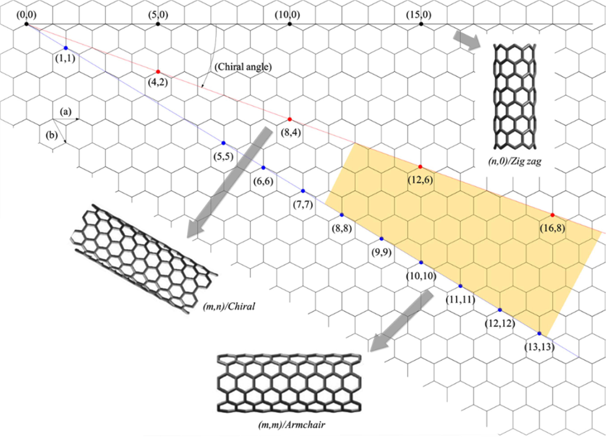
As mentioned previously, depending on the chirality,
SWCNTs can be metallic or semi-conducting. Due to this unique
structure, SWCNTs have been studied in focus. The
degree of twist of the graphite sheet is characterized
by a pair of vectors (n, m), which are called chiral
vectors, where the integers n and m represent the number of unit vectors along
two directions in the honeycomb crystal of graphene [41], as shown in Fig. 2.
Because of the varying degrees of twist of their rolled graphite sheets along
the length, CNTs can have a different chiral structure. In case of,
m = 0, the nanotubes are called “zigzag structure”; if
n = m, these nanotubes called “armchair structure”; other nanotubes
are called “chiral structure”. In addition, if (n – m) of the chiral vector is
a multiple of 3, SWCNTs exhibit a metallic behavior; if (n – m) is not a
multiple of 3, it exhibits a semi-conducting behavior. This is due to the
change in density of the Fermi energy state. Also depending on their diameter
and the helicity of the arrangement of graphite rings in the walls, they have been
demonstrated to possess unique electronic, photonic, magnetic,
thermal, and mechanical properties. Due to their unique physical and chemical
properties [42], Nanotubes are being used in a wide range of
applications, such as nano-electronic devices [43],
interconnects [44], sensors and actuators [45], energy storage media [46], and
field emitters [47] et al.
Theoretical
studies have suggested that the ideal CNTs are ballistic conductors for distances
in the order of a micron [48]. The 1D
confinement of electrons combined with the requirements for energy and momentum conservation leads to ballistic
conduction. The electrical properties of SWCNTs have been studied intensively
[49], often for the purpose of developing devices such as interconnects [50] or
CNTs-based transistors [51]. In contrast, the electrical properties of MWCNTs
have not been investigated at the same level of detail, due to their additional
complexities arising from the
structure, as every shell has different electronic characteristics and chirality, besides the
interactions between them [52].
However, for MWCNTs with both ends connected by metallic
contacts, electronic transport is dominated by outer-shell conduction at low
temperature and bias [53]. Theoretical models and experimental results point to
the critical role of shell-to-shell interactions to significantly lower the
resistance of MWCNTs with a large number of walls [54, 55]. Theoretical
calculations [56] and experimental results [57] indicate that CNTs are stiffer
than diamond, exhibiting the highest Young’s modulus and tensile strength.
Since CNTs are rolled-up graphene sheets, a first approximation for their
elastic modulus would be that of graphene, being approximately 1,000
GPa, five times that of steel. Many experiments have
confirmed the theoretical predictions. For example, Yu et al.
[58] measured the CNTs tensile load using Atomic Force Microscopy (AFM), and
found Young’s modulus values ranging 320 and 1,470 GPa (average 1,002
GPa), which is consistent with the value estimated by Krishnan
et al. [59] based on the observations of SWCNTs freestanding room temperature
vibrations in transmission electron microscopy (TEM). Using first-principles
calculations, Zhou et al. [60] estimated the Young’s modulus of 760 GPa and
tensile strength of 6.2 GPa for SWCNTs, while molecular dynamics studies by Yao
et al. [61] led to values of 3.6 GPa for Young’s modulus, and of 9.6 GPa for
tensile strength. Using TEM, Demczyk et al. [62] measured a Young’s modulus of
0.9±0.18 TPa and a tensile strength of 150 ±45 GPa, which are comparable to
those of graphene sheets.
Innertube
coupling in SWCNTs and inter-shell coupled
MWCNTs result in a low-temperature specific heat that resembles that of 3D
graphite [63]. Pop et al. reports the thermal properties of a suspended
metallic SWCNTs were extracted from high-bias (I-V) electrical characteristics
achieved by Joule self-heating over the 300 ~ 800 K temperature range
[64]. They measured a thermal conductivity of almost 3,500 Wm–1K–1
at room temperature (RT) for a 2.6 mm length of SWCNT with a diameter of 1.7 nm
and developed a model of thermal conductivity as a function of nanotube
diameter and temperature. Similarly, Kim et al. [65] measured a thermal
conductivity above 3,000 Wm–1K–1 at RT for MWCNTs using a
microfabricated suspended device. The property of field emission relates to the
extraction of electrons from a solid material by tunneling through the surface potential barrier. The emitted current
depends directly on the local
electric field at the emitting surface and its work function. The
Fowler-Nordheim model [66] shows an exponential dependence of the emitted
current on the local electric field and the work function. Given that the
emitter shape (geometric field enhancement) and the chemical state of the
surface have a strong impact on the emitted current, the small diameter and
elongated shape of CNTs lead to a high geometrical field enhancement, making
them ideal candidates for field
emission applications, such as displays
or triodes [67]. Another promising field of CNTs is nanostructure-based solar
cells [68]. The dispersion of CNTs in a solution of an electron donating
conjugated polymer is perhaps the
most common strategy to implement CNT
materials into organic photovoltaic devices to obtain higher efficiency. It has
been reported that enhancements of more than two orders of magnitude have been
observed in the photocurrent from
adding the SWCNTs to the poly (3-octylthiophene) matrix [69]. As is well
known, CNTs have 1D and wire-like
structure, making them better at forming electron- or hole-transporting
highways in the cell, and their large
surface area enhances the separation of the electron-hole pair, leading to conductivity several times
greater than that of conducting polymers. In these cells, they can act as both electron donors and acceptors,
depending on the redox properties of
the other component. The use of CNTs in dye-sensitized solar cells has achieved
double efficiency of this kind of photoelectrochemical solar cell [70].
Fabrication
method of carbon nanotubes
The most common method for synthesizing CNTs is as
follows:
1) Arc-discharge [71-74]
2) Laser ablation [75-77]
3) Chemical
vapor deposition from hydrocarbons (CVD) [78-82].
Techniques such as arc discharge and laser ablation enable
the synthesis of non-substrate CNTs with good crystallinity at high
temperatures. This simple method is the most widely used technique for
synthesizing CNTs without a substrate. The choice of the most suitable synthesis method depends on the properties and
possibilities required. Therefore, much research is underway to
increase yield and efficiency to
reduce current production costs. Mass production capability is key to using
CNTs in composites. Compared with CVD
processes, arc discharge and laser
cutting methods are costly, while CVD is the most suitable technique for
scale-up. In order to use CNTs in composites, large quantity production
capacity is the key [83]. Therefore, this research will mainly focus on the CVD
method.
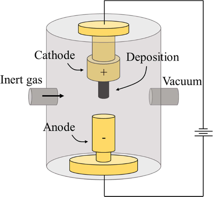
Electric-Arc discharge
Arc discharge, a method developed by Kratschmer et al. [73],
was the first available method for mass-producing
both SWCNTs and MWCNTs. This technique has been used
initially for fabricating carbon fibers and fullerenes, which may be the reason
for CNTs not being characterized, even though they were produced before 1991.
For example, Roger Bacon synthesized “thick” carbon whiskers in the
early 1960s, as mentioned by Yakobson and Smalley [74]. One
can imagine that if he had a HRTEM, he could have found CNTs in the soot. In
this technique, CNTs produced by striking an arc electrodes in an inert
atmosphere (e.g., He or Ar). If a catalyst is added to one of the electrodes,
they can be easily obtained. The mechanism is based on energy transfer between
the target material, graphite, which is kept at temperatures close to its
melting point, and an external radiation source, as shown in Fig. 3. The
technique has a major advantage, in that it is possible to produce CNTs with
good crystallinity by tuning the parameters, which leads to their superior
electrical and mechanical properties. This may be caused by the high
temperature where the process operates, even higher compared to CVD. The major
drawback is that CNTs products have to be separated from
other carbon products and catalyst residue.
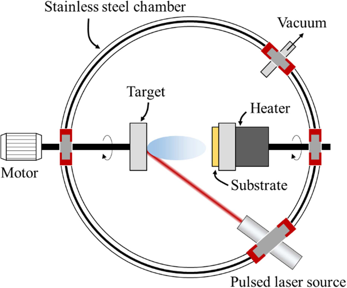
Laser ablation
This method was first introduced by Smalley’s group [75]
and was used for the production of fullerene clusters. The principle and
mechanism of this technique are similar to the arc-discharge technique, but the
difference is that the graphite pellets containing the metal-ion
catalyst (e.g., Ni or Co) are strike by a laser to generate
clusters. Pulsed or continuous laser irradiation to
species for vaporizes the carbon and catalysts. The vaporized species are led
to a water-cooled collector by a flow gas, where they condense, as shown in
Fig. 4. Using this method, MWCNTs can be collected in the soot with diameter of
1.5 to 3.5 nm, and with length of up to 300 nm [76, 77]. The function of the
reaction temperature (1,200 oC is optimum temperature for the best
quality of CNTs. By introducing small quantities of metal catalyst in the
pellet, SWCNTs can be achieved with good crystallinity. Unfortunately,
this technique has disadvantage for economic issues, because the process
involves high-purity graphite rods, the higher laser powers was required and
the amount of CNTs that can be manufactured per day is not as high as for the
arc discharge method.
Chemical vapor deposition (CVD)
Chemical Vapor Deposition (CVD) is a commonly used method
for the manufacture of thin films and is very different from the two methods
mentioned above in the synthesis of CNTs. CVD has the low set-up cost, easy
control of experimental parameters, simple synthesis conditions
and easy to scale-up to mass production make it one of the most widely used
methods of CNTs in recent years. CVD methods can be classified into various
methods such as plasma-enhanced CVD and thermal CVD
etc. In particular, Catalytic CVD (CCVD), which is a
CVD with catalytic pyrosis of hydrocarbon, is applied to the synthesis of CNTs,
which enables high yield of nanotubes [78, 79]. This technique provided
various advantages over other techniques, where CNTs are grown
over metal-ion catalysts containing nanoparticles of
transition metals (e.g., Ni, Fe, Co, Cu) or related oxides by the decomposition
of a various carbon source (e.g., CH4, C2H2,
etc.) [80-82]. Previously, while most CVD-grown CNTs were “spaghetti-like” and
defective, the potential of the method to satisfy technological requirements
was recognized. Since 1998, substantial and rapid progress has been made in the
development of CVD to establish it as a highly controlled
technology for producing CNTs. To date, it is possible to fabricate high-quality
SWCNTs and MWCNTs in bulk, or directly onto substrates as a raw
material [83-85]. In addition, it can be integrated as a step-in chip
fabrication, and by appropriate patterning, can be used to synthesize CNTs in
required locations on substrates, although a complete understanding of the
growth mechanism of CNTs is still unclear at this time. Fig. 5 shows the
synthesis techniques that we used.
|
Fig. 1 Illustration of ideal (a) fullerene, (b) graphene, and (c) SWCNT and MWCNT (all cited from Wikimedia Commons). |
|
Fig. 2 Chirality (θ) of SWCNTs derived by rolling the Hamada vector of the graphene sheet ((Reproduced from ref. 8, Copyright 2012 Springer). |
|
Fig. 3 Schematic diagram of electric-arc discharge apparatus (Reproduced from ref. 8, Copyright 2012 Springer). |
|
Fig. 4 Schematic diagram of laser ablation apparatus (Reproduced from ref. 8, Copyright 2012 Springer). |
|
Fig. 5 Schematic of CNTs production by CCVD (Reproduced from ref. 8, Copyright 2012 Springer). |
To apply nanostructures is one of the driving forces of
material development. The possibility of controlling the microstructure
complexity and interfacial and interconnectivity of microstructural units is a key technology for
producing new materials with improved multifunctional properties.
Recent research activities have addressed the question of how to transform
hierarchical cellular structures of trees to provide
specific functional properties [86-89]. Due
to the genetic evolution process, biological structures
exhibit excellent strength in low density, high stiffness and elasticity, and
are resistant to micro damage, as well as at the macroscopic scale. Wood is a
natural compound with cellulose, hemicellulose, and lignin as
major biopolymeric components and additional macromolecular
compounds. Carbonized wood is being used in a wide range of industries as the
demand for charcoal increases with the growth of the metal
industries.
Recently, carbonized wood has been used as activated
carbon in a variety of applications, such as fibers, composites, filters, and
catalyst supports [90]. As the importance of the fine chemical industry grows,
there is much interest and research in the micro reactor process
using activated carbon supported precious metal catalysts
[91]. The carbon support may be prepared in powder, pellet, or honeycomb form,
and is used as a catalyst filter support or absorbent. Catalysts such as Cu,
Pt, Ir, Ru, Pd, Rh, or Mn can be applied, and are used for the thermocatalytic
decomposition of methane for hydrogen production, without low
temperature selective catalytic reduction NO or CO2
[92]. However, carbonized wood is more difficult to commercialize, because it
has a lower specific surface area (SSA) than commercial activated carbon of
400 ~ 1,200 m2/g [93]. Mohan et al. [94] obtained
carbonized wood with SSA values of 2.04, 2.73, 25.4, and 1.88
m2/g by carbonizing oak, pine, oak
bark, and pine bark at 400 ~ 450 oC,
respectively. A recent breakthrough is Yao et al. [95], who
carbonized bamboo, sugar barge, and hickory wood at 600 oC,
and obtained SSA values of 234, 375.5, 388.3, and 401.0 m2/g,
respectively, under optimized heat treatment conditions [96].
In addition, in the case of interconnected biomimetic
structures, it is still a technical challenge to produce CNTs-inserted
complexes in all directions. Open pore matrix
composites, which are used as trusses depending on the
degree of porosity and the degree of filling with nanotubes,
can be applied as multifunctional engineering composites,
such as filters. CNTs has received special attention,
because it has excellent water treatment ability to filter
organic and inorganic pollutants [97, 98]. CNT-reinforced composite materials
can also potentially improve their mechanical properties.
Wood
structure and composition
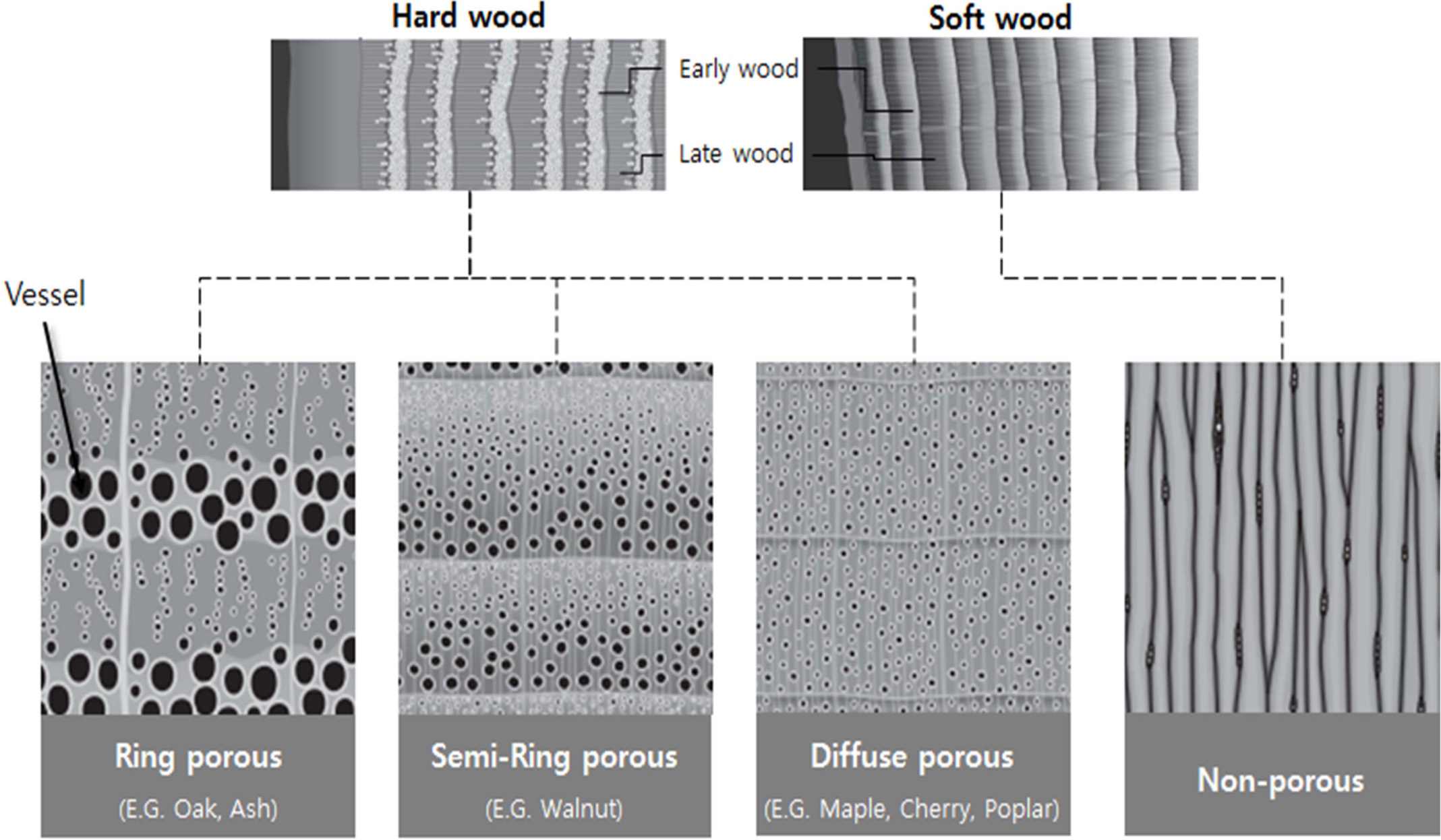
According to Ramirez-Rico et al. [99], the structure of
wood can be roughly divided into two groups for soft- and hardwood, according
to its microstructure and composition. The composition of the cell walls is
determined by the nature of the wood and the wood-derived product, as shown in
Fig. 6 [100]. This can be described as a lamellar or layered microstructure, in
which each layer is composed of cellulose, hemicellulose,
and lignin (lignocellulose). Cellulose is usually a long polymer chain (up to 1
μm long), agglomerated with microfilaments aligned with the longest dimension
of the cell. Hemicellulose is a short chain connecting cellulose
microfilaments, and lignin occupies the space left by the cellulose and
hemicellulose chains [99, 101, 102]. In addition to the presence of pores and
cells, the tree also shows two types of macrostructures: light rays,
and growth rings. Light rays are horizontally aligned cells that are used for
nutrient storage, and are released in three axes, while growth rings are
concentric circles that change pore size, due to seasonal changes in tree growth.
Since there is no fluid pathway, the softwood of gym plants, such as conifers,
is generally referred to as non-porous, while the hardwood of pizza plants is classified
as porous, semi-circular, or porous, depending on the shape
of the growth rings [103, 104].
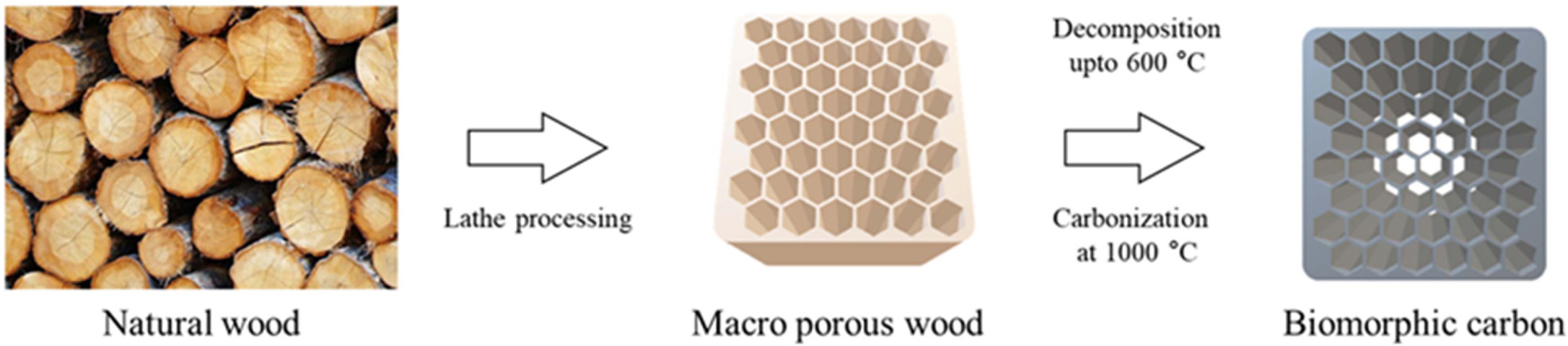
Carbonization
and pyrolysis
Pyrolysis of wood to produce a carbon support biomorphic
carbon materials (BCMs) by slowly heat up to a temperature above 800 °C with
the natural wood precursor in an inert atmosphere (typically Ar or N2).
In the pyrolysis process, the other polymer components of the wood decompose
hemicellulose at 200 ~ 260 °C and decompose cellulose at
240 ~ 350 °C and lignin at 280 ~ 500 °C,
stepwise [105]. In this work, to avoid collapse of the specimen
structure during the carbonization process, the specimens were slowly heated
in N2 gas flow 10 cm3/min in a horizontal electric
furnace at a heating rate of 0.5 °C/min to 600 °C for 6 ~ 8
h. Subsequently, the temperature was raised to 1,000 °C
at a rate of 3 °C/min to obtain a porous carbon template.
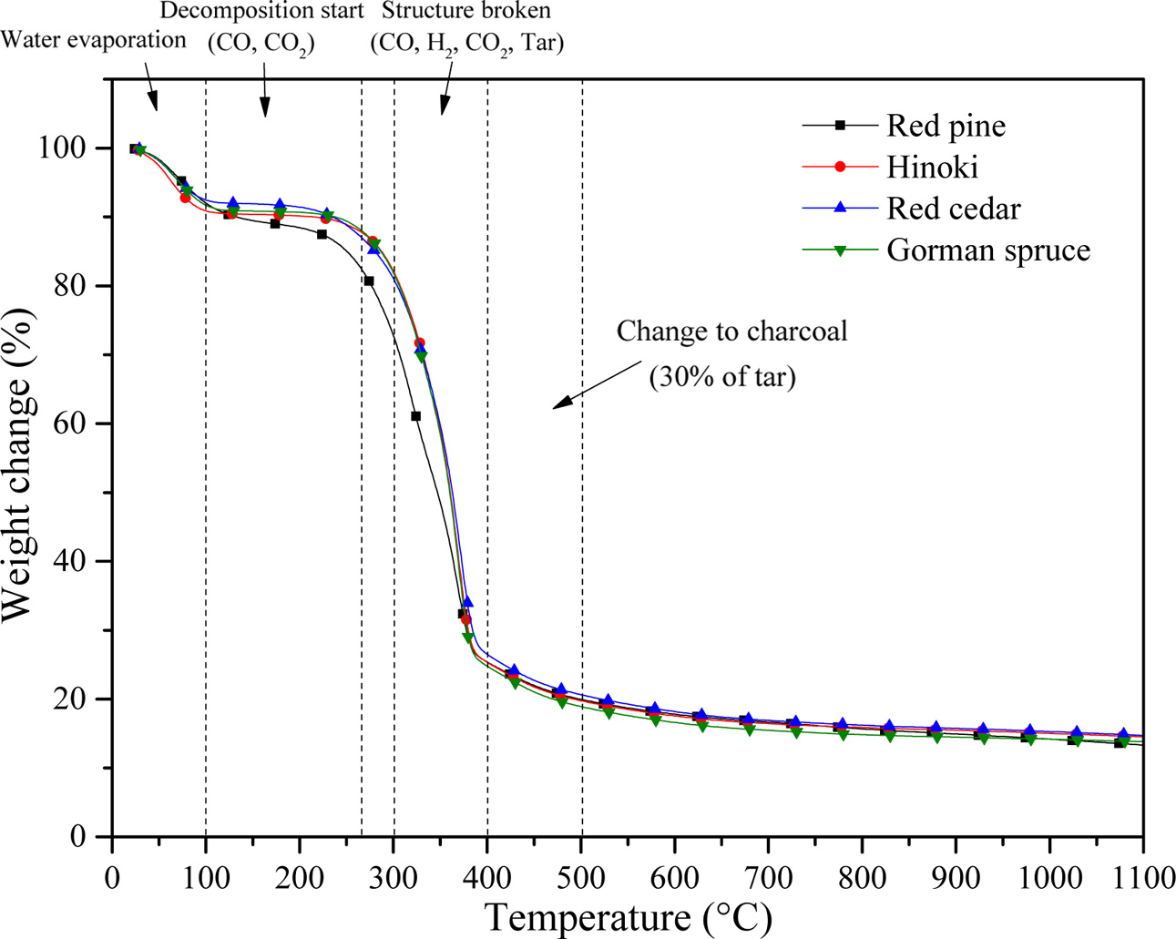
Fig. 8 shows that H2O, carbonyl groups, CO2
acids, and alcohols are released, due to degradation of the biopolymer
structure at temperatures up to 600 °C during pyrolysis. On the other
hand, the major biopolymer components of the cell wall material are rearranged,
and converted to carbon struts. Upon thermal decomposition at the initial stage
(T ≤ 250 °C), evaporation of water and decomposition of CO and CO2
begins with a weight loss of 15 ~ 20%, and then the wood structure
breaks CO, H2, CO2, and changes into charcoal having
about 30% tar between 300 and 500 °C with a weight loss of almost 80%.
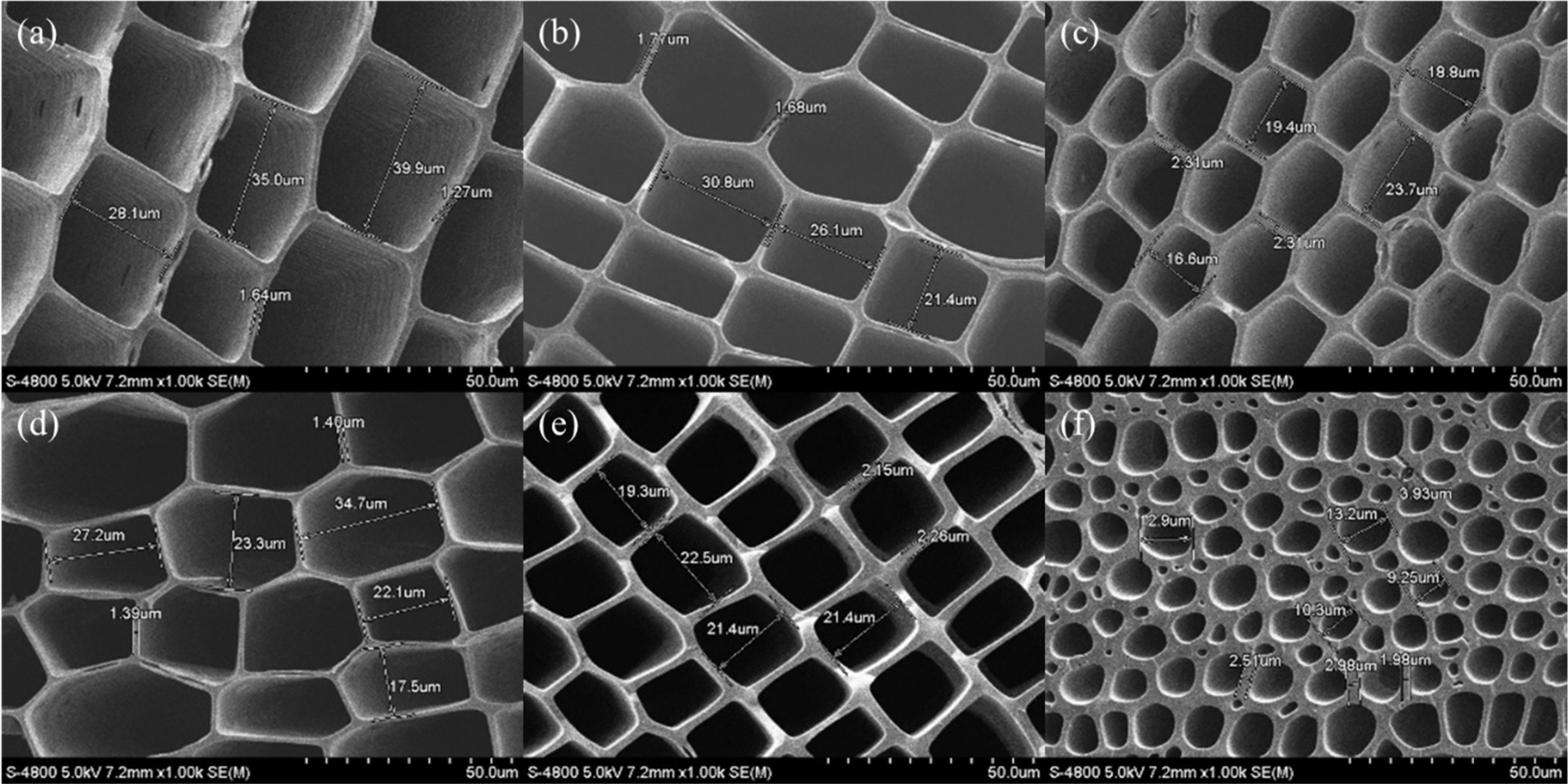
Fig. 9 shows the microstructure of the axial cross-section of the biomimetic
carbon material from pyrolysis of several different precursors used as the base
substrate for CNTs synthesis. In all cases, the unique anatomical
characteristics of the tissue can be maintained during pyrolysis,
producing porous materials that are composed mainly of honeycomb and
ring-porous carbon structures [106]. It is also clear that after pyrolysis, the
pore shape and distribution of the original wood are preserved.
Fig. 9(a) and (b) show a hexagonal cell structure, in
which the microstructure of hinoki and red cedar has a pore size (long side *)
in the range 18.8 to 23.7 μm, while each cell wall thickness is of about
2.30 ~ 1.40 μm. Fig. 9(c), (d), and (e) show the microstructure of
North American red pine, red pine, and Gorman spruce with a rectangular cell,
and square structure with pore size ranging 19.3 to 22.5 μm, and cell wall
thickness of about 1.45, 1.72, and 2.21 μm, respectively. Fig. 9(f) shows the
microstructure of Mahogany contains hollow channels of various diameters that
originate from tracheid cells that are parallel to the axis of the tree. The
hollow channels of the biocarbon template have a uniform arrangement, where the
black part is lumen, and the grey part is a carbon layer that is formed by carbonization
of the cell wall. The difference in diameters of hollow
channels is attributed to the non-uniform distribution of the texture of the
wood. The average range of diameters of cell is about 5 ~ 30 μm, and
the cell wall is about 2 ~ 3 μm thick. Most of the cellular pores
show a rectangular shape, and the distribution shows a regular net with carbon
wall joined to each other, as shown in Figs. 9(c) to (e). The topologically uniform
arrangement of cell of early wood is interrupted by growing
ring patterns, where late wood cell show a significantly higher strut thickness
[107].
Physical
properties of biomorphic carbon materials
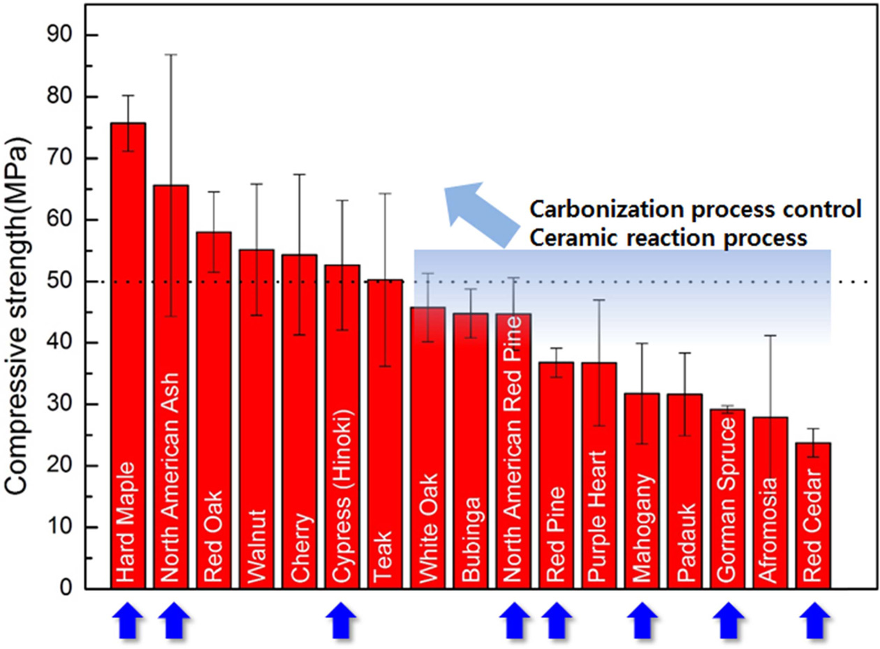
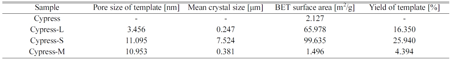
Table 2 shows the physical properties of BCM with its
unique structure obtained by pyrolysis of wood varieties,
such as Cypress, Red pine, Gorman spruce, and Hard maple, respectively [108].
Carbonaceous materials impregnate and react with coated
oxides and nano-oxides that can be used in a variety of applications, as well
as filtration and catalyst support. Greil’s research team [109, 110] was one of
the first to report the characteristics of melt-impregnated bio SiC/Si, the
properties of carbon preforms, and the mechanical properties of porous bioSiC
obtained by gas infiltration [111-113]. Gutierrez-Mora et al. [114] and Presas
et al. [115] studied the bending strength and fracture toughness of
various bioSiC/Si materials derived from hardwood, using
indentations to measure the hardness of eucalyptus, beech, and
pine-derived bioSiC/Si composites [116, 117]. Park et al. [118] studied flexion
and compressive strength as a function of the precursor density of bioSiC/Si
synthesized by various precursors. Hou et al. [119] measured the bending
strength as a function of penetration time to study the possible effects on the
final properties of the material. Kaul et al. [120] measured the mechanical
properties such as elastic modulus, compressive strength, and fracture
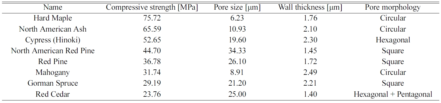
toughness of the porous bioSiC from other precursors. Table 1 shows that the
compressive strengths of Hinoki and Red cedar with pore size of 19.60, 25.0 μm,
and wall thickness of 2.3 and 1.73 μm are 52.65 and 23.76 MPa, respectively.
In addition, the Red pine having a pentagonal and
hexagonal honeycomb structure has a pore size of 36.78 μm, a
wall thickness of 1.72 μm, and a compressive strength
of 23.76 mpa. Fig 10 shows that the carbonized carbon
materials reveal increased compressive strength due to the ceramic reaction. Fig. 7 Fig. 10
|
Fig. 6 Axial sections of wood structure from ring porous hardwood and non-porous softwood (Modified from T. Nunlist, Popular Woodworking, Dec. 2012.). |
|
Fig. 7 Carbonization process of natural wood. |
|
Fig. 8 TGA curves of carbonized biomorphic carbon template from red pine, Cypress, Red cedar, and Gorman spruce. |
|
Fig. 9 Macrostructure of hinoki (a), red cedar (b), north american red pine (c), red pine (d), Gorman spruce (e) and Mahogany (f) (Reproduced and modified with permission from ref. 5, 107 and 156, Copyright 2018 Hanyang University and Inderscience publishers). |
|
Fig. 10 Compressive strength of biomaterials after the carbonization. |
In principle, finely dispersed, nanometer-sized metal
particle catalysts that preserve their morphology at the CVD processing temperatures
are required, because controlling the morphology of the
catalytic particles during CNTs growth strongly affects
nanotube characteristics, such as thickness, uniformity, and
yield. However, as the size of the metal particles decreases to the nanometer
scale, they tend to agglomerate. To prevent this, porous materials have been
proposed as supports. A porous support showing a non-continuous surface and
high SSA can not only contribute expressively to particle stabilization and
produce a fine dispersion of well-defined particles, but also radically
increase the number of catalytic particles, thus increasing the
number of nucleation sites, which are all advantageous to the
synthesis of CNTs [121]. Commonly used substrates in CVD include silicon [122],
quartz [123], silica [124], silicon carbide [125], alumina [126],
alumino-silicate (namely, zeolite) [127, 128], and magnesium oxide [129]. Among
all the catalytic supports, zeolites being molecular sieve materials with pore
diameters in the range 3 ~ 10 Å have had a significant impact due to
their structural homogeneity, and high reactive surface area, which makes them
excellent host candidates for different types of adsorbing
molecules [130]; and hence zeolites could be used as supports
for catalyst particles to synthesize and grow CNTs [131]. In this review, the zeolite
(LTA, Silicalite-1) and meso-porous SiO2 are used
as the templates for supporting catalyst nanoparticles to
synthesize CNTs biomorphic carbon composites via the CCVD method.
Template-coated
biomorphic carbon materials
Zeolites are typically defined as crystalline
aluminosilicate with the chemical composition Mx[(AlO2)x(SiO2)y]·nH2O.
Their structure is based on a three-dimensional regular connection of [AlO4]5- and [SiO4]4- tetrahedral units,
which are linked to each other via bridging oxygen atoms. As each aluminum atom in the framework generates negative charge, cations (M+) must
exit for charge balancing in the framework [132]. The framework structures
create unique three-directional features, high regular arrays of very open void
spaces that are often termed cages or
channels. Typically, the window diameter of its pores ranges 3 to 8 Å, while the inner diameter of interior
spaces ranges 5 to 13 Å. Up to now, 235 types of zeolite frameworks are
registered, having different 3-dimensional regular opened nanopore or
nanochannel structures. Based on
their structural features having high
surface area, zeolites are commonly
used as commercial adsorbents [133]
and catalysts [134, 135]. Recently, this unique structural feature provides a
vast templating system in applied synthesis fields, such as quantum dot [136-139], organic molecules [140, 141], etc. In
particular, zeolites have also been
extensively tested as template for carbon nanotubes, because their uniformly
arranged nanopores and nanochannels
can serve as nano templates for liberating series of three-dimensional ordered
micro- porous carbon materials [142, 143]. We term this material ‘zeolite-templated carbon’ (ZTC). Generally, ZTCs
of the three-dimensionally ordered
framework by replicating the zeolite template are obtained only when the
synthesis is carefully performed with
appropriate conditions, which is comprised of three steps: (a) uniform carbon
introduction only inside the zeolite nanochannels, (b) heat treatment, and (c)
template removal [144, 145]. The first formation of porous carbon using zeolite
templates was reported in 1997 with
description of some of the unique advantages of this technology. By
depositing graphene monolayers
uniformly on the internal surface area of zeolites, and by etching the zeolite
using a com- bination of acids, porous carbon replicas may be
produced with an ordered array of
microspores. The large variety of zeolites with more than 200 types available
allows an appropriate template to be selected for the desired pore size in a
ZTC [146]. This review addresses surface modification of the mesoporous
templates, such as Linde Type A (LTA) zeolite [147, 148], silicalite-1
[149-151], and mesoporous silica [152]. Among these matrices, zeolite is an
excellent template for supporting or encapsulating catalyst nanoparticles due
to the well-defined pore structure and high surface area and is responsible for
catalyst particle stabilization and the fine dispersion of nanoparticles [153]. Generally, silicalite-1 is pure SiO2 zeolite, and has high
surface area. It also has the potential to load catalytic materials on the
cavity of silicalite-1 of about 0.5 ~ 0.55 nm. But it is difficult to
load some materials on its surface firmly or in its pores, due to its smooth
surface and small cavity. In order to meet growing environmental challenges, it
is important to explore new technologies to treat or synthesize silicalite-1,
which can load a large amount of other materials, and retain its large surface
area [154, 155]. The mesoporous structure features a large specific surface
area and pore size of 2 to 50 nm in diameter. Mesoporous silica nanoparticles
(MSNs) can also be used as a host material to carry therapeutic agent or for
molecule encapsulation and can be used as a template for the synthesis of CNTs.
Good biocompatibility, high
loading capacity, and the possibility of attachment of a target ligand for
specific cell recognition, or a well-defined and adjustable porosity design,
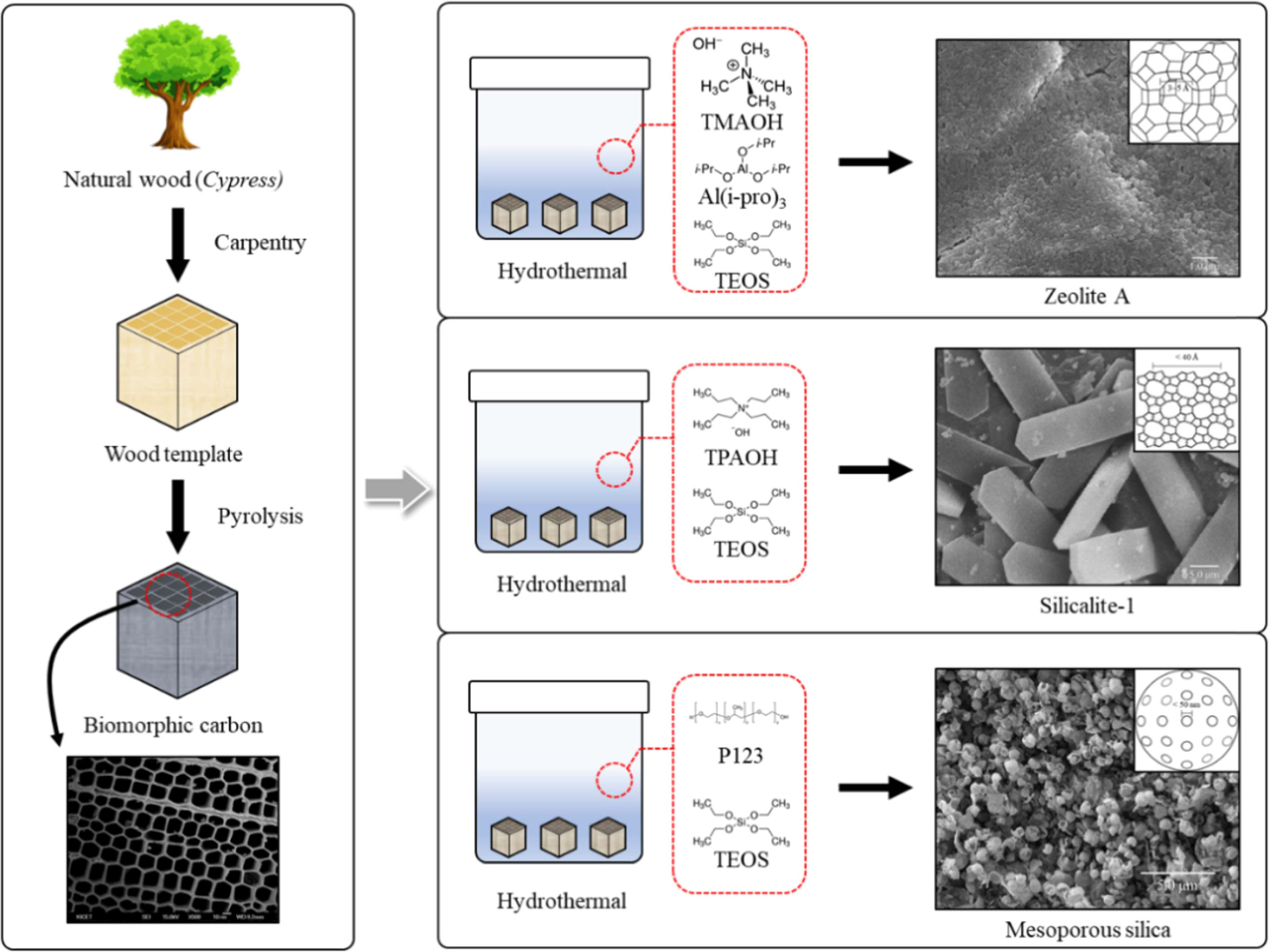
make MSN suitable for drug delivery. Fig. 11 shows a new process for
synthesizing and coating LTA zeolite,
silicalite-1, and mesoporous silica onto biomorphic carbon materials [156].
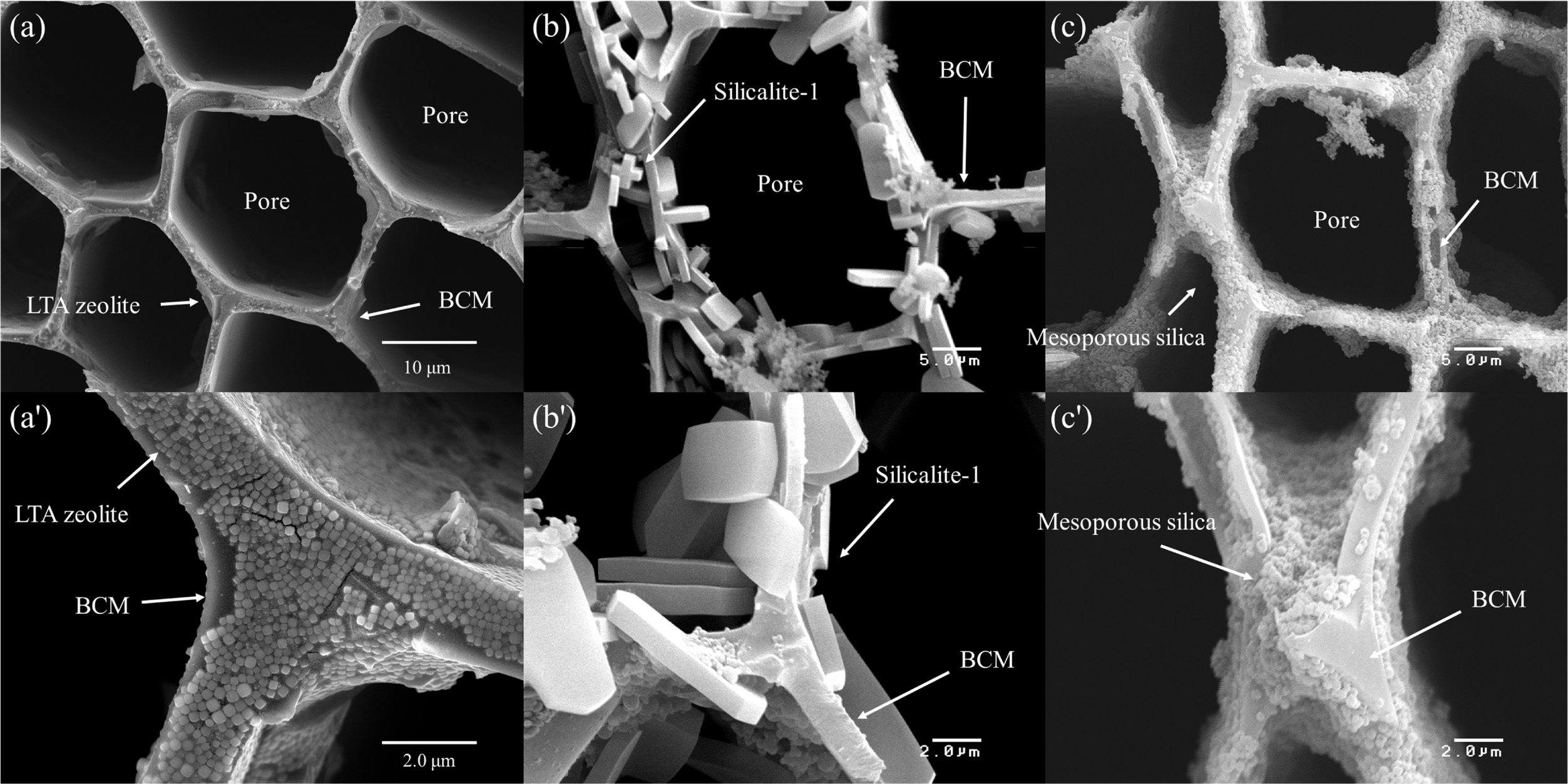
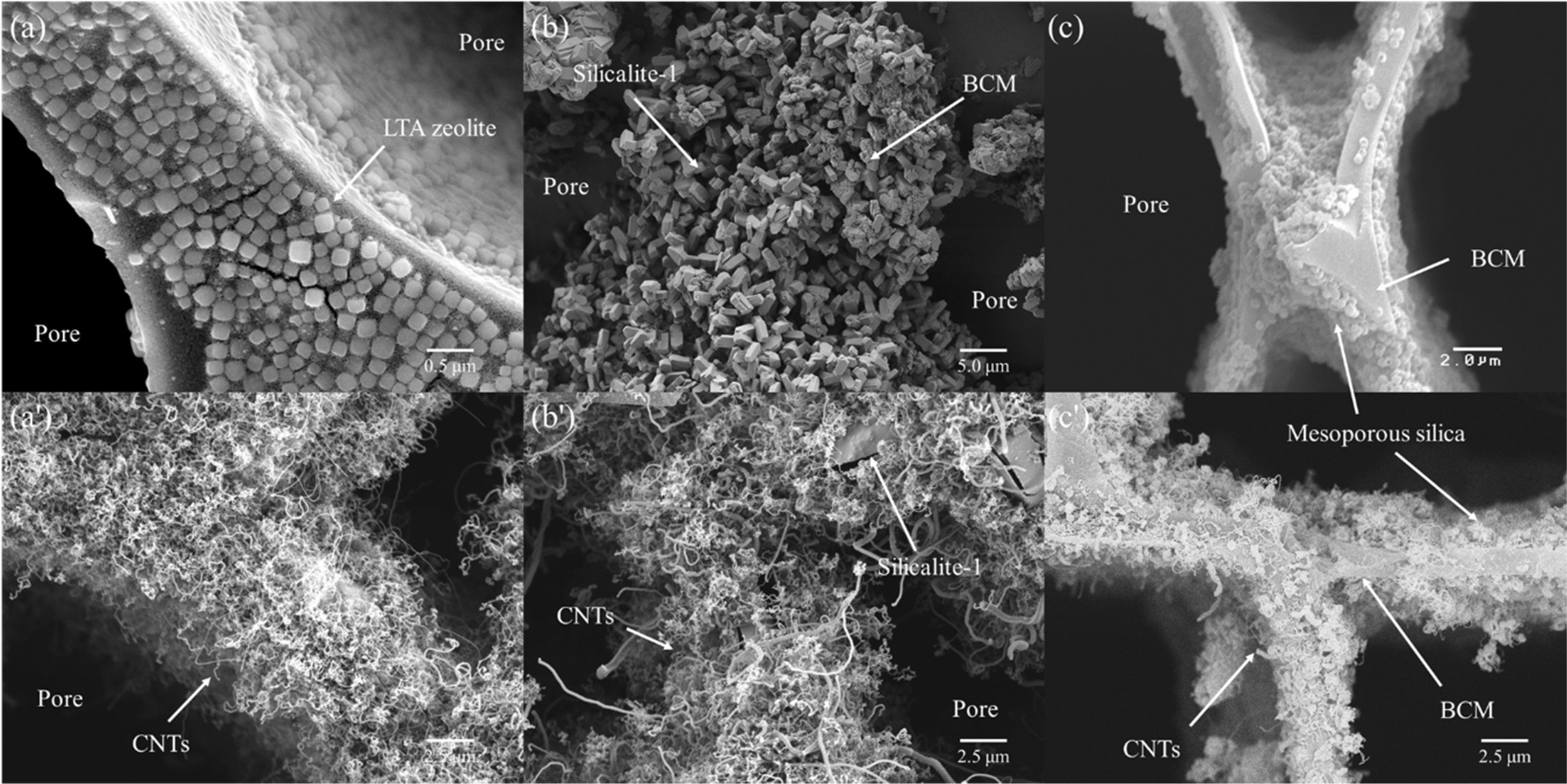
Fig. 12 shows microstructures of (a) and (a') LTA type
zeolite, (b) and (b') silicalite-1, and (c) and (c') mesoporous silica template
coated cypress BCM. The LTA zeolites are finely coated inside and outside of
the honeycomb structure, which can be observed in Fig. 12 (a'). The cubic shape
of LTA zeolite crystals has been achieved with the size of around 120 nm in a
configuration with a fine layer of well-controlled cube crystals. The cube
{001} is composed of six perfect square faces that make angles of approximately
90 o. The crystal structure of LTA zeolites
was homogeneously synthesized and coated on the surface of the
template by an in-situ hydrothermal process. Generally, the framework of
LTA zeolite crystals can be explained in terms of two types of polyhedra; one
is a simple cubic alignment of eight tetrahedra, and is termed D4R, while
the other is a truncated octahedron of 24 tetrahedra or cages,
as previously described for the sodalite-type minerals [157, 158]. As observed
with higher magnifi- cation, the
5.0 μm silicalite-1 particles were entirely interlocked and coated on the
surface of BCM. The images revealed the presence of a continuous and smooth
mesoporous silica film layer of less than 1.0 μm [156].
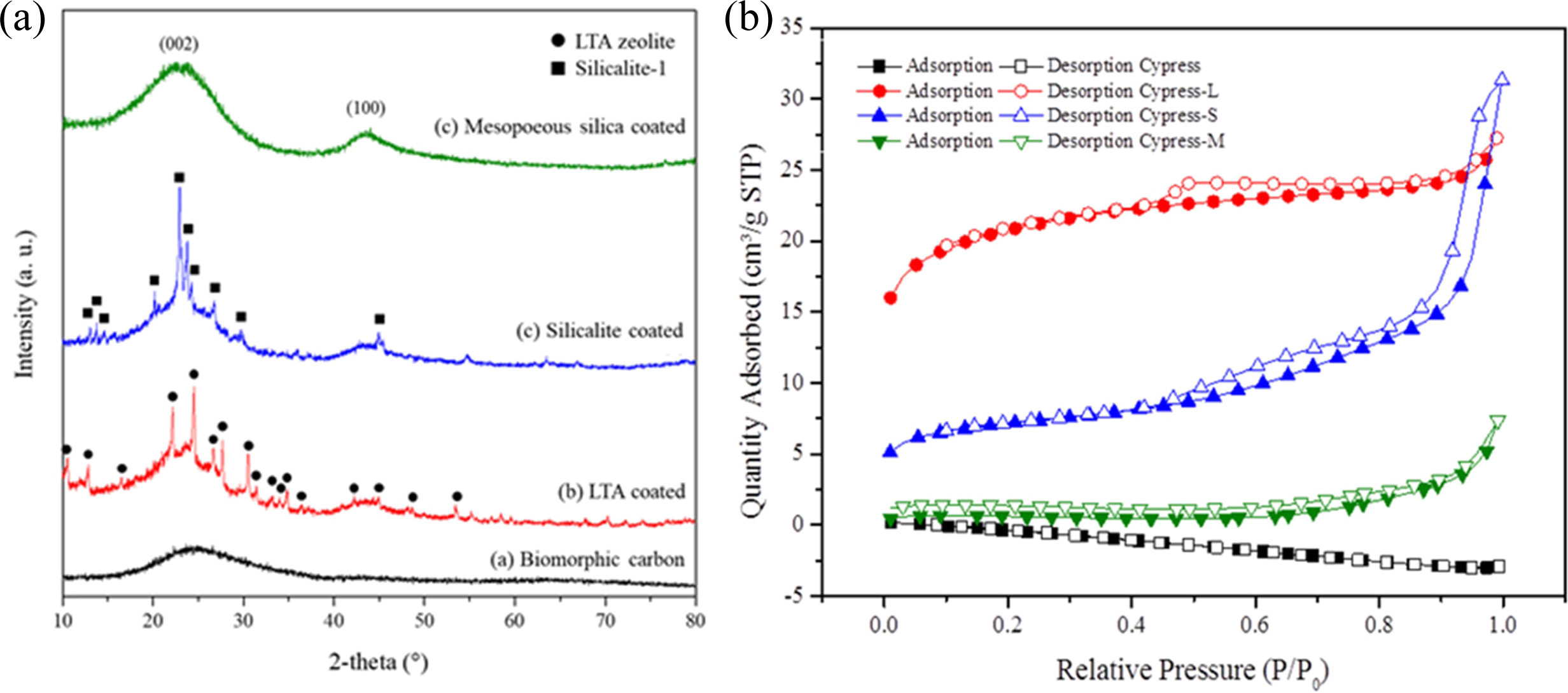
Fig. 13(a) shows XRD patterns of LTA, silicalite-1, and
mesoporous silica template synthesized on the surface of the BCM. These XRD
plots show different peaks, which indicate monolayer and multi-layer fine coating
of the template. These peaks were then compared to JCPDS
files. Compared to JCPDS file # 97-002-4901, the corresponding peaks reflected
the yield of LTA phase, 2θ = 10 ° (220), and 24 ° (600). A single
phase with an average lattice constant of 24.61 Å was found in the obtained
XRD. This is a simple cubic arrangement of eight tetrahedra with D4R [21, 156].
Similarly, when the obtained XRD plots were compared to
the JCPDS 42-0023 original JCPDS file for silicalite-1,
corresponding peaks were also found. This assures the synthesis of silicalite-1
in the BCM. Randomly oriented silicalite-1 crystals were coated as shown in
Fig. 12(b). BCM was also coated with mesoporous silica. However, it was hard to
recognize it with wide angle XRD, due to the mesoporous silica’s properties.
Instead, it needed to be analyzed with small angle XRD [22, 156]. The peak
intensity was the background of amorphous carbon.
Fig. 13(b) shows the N2-adsorption/desorption
isotherms of BCM coated with LTA, silicalite-1, and mesoporous
silica. According to the International Union of Pure and Applied Chemistry
(IUPAC) classification, isotherms of all the samples studied belonged to type
IV [23, 160], suggesting that these adsorbents are mesoporous materials.
Capillary condensation phenomenon may occur in their pore channels. Fig. 13(b)
shows that the N2-adsorption capacity of silicalite-1
seems to be greater than that of LTA zeolite or mesoporous
silica. This is probably because the pores of LTA zeolite and
mesoporous silica are partially covered by the active ingredient [161, 162],
thus reducing the surface area. Furthermore, the hysteresis loop shifts in the
relative pressure range of 0.4 ~ 1.0. The BET isotherms graphs (Fig.
13) show a typical type (IV) with type II-like hysteresis loops, indicating the
presence of mesopores in all samples (LTA zeolite, silicalite-1, mesoporous
silica). The position of the inflection point of P/P0 is related to
the diameter of the mesoporous range. The sharpness of the step shows uniform
mesoporous size distribution. Table 3 summarizes the results of BET and the
yield. Templates were coated on BCM to increase the specific
surface area, especially of silicalite-1. The BET surface areas of the original
carbonized cypress, LTA zeolite, silicalite-1, and mesoporous silica were
2.126, 65.977, 99.634, and 1.496 m2/g, respectively [156].
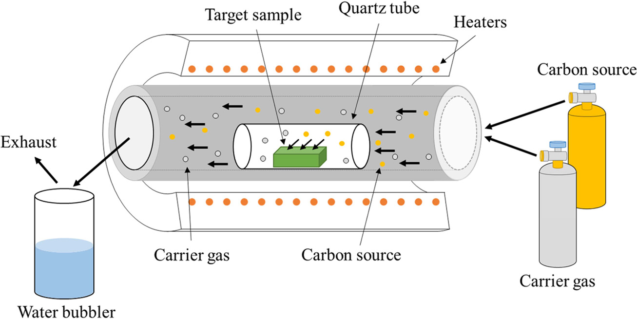
Fabrication
of CNTs nanofilter composites
Fig. 14 shows that catalytic decomposition of acetylene
(C2H2) on the BCM was carried out in a quartz boat
centered in a horizontal tube furnace. The synthesis was carried out with
application of the three different processing routes for CNTs composites. First
of all, biomorphic carbon material was produced by the carbonizing
reaction. Secondly, LTA [148] and silicalite-1
[151] were synthesized within and coated concurrently on the
carbon template, which was then subjected to colloidal process, resulting in
the formation of Co ions loaded on template-coated BCM substrate; and finally,
the CCVD method was used for the synthesis of CNTs, as shown in
Fig. 14(c) [163, 164]. To maintain neutrality, the
temperature was elevated at a rate of 5 °C/min to the desired
reaction temperature in a nitrogen atmosphere (200 sccm). Carbon nanotubes were
grown by the introduction of carbon feeding gas C2H2@ 10
sccm. CNTs were separately synthesized at 650 and 700 °C for 40, 60, 120, and
180 min, respectively.
Fig. 15 shows FE-SEM images of multi-walled CNTs grown on
Co- catalyst loaded LTA-, silicalite-1, and mesoporous SiO2-BCMs for
60 min at 650 °C, respectively. Figs. 15(a), (b), and (c) clearly show the
CNTs synthesized on the BCM keeping template as a base for the FESEM images in
overview, respectively. All templates were uniformly and tightly coated on the
BCM surface. All CNTs were synthesized as multi-layered carbon nanotubes like
hair, so the yield of CNTs was very low in mesoporous SiO2 template,
as shown in Fig. 16.
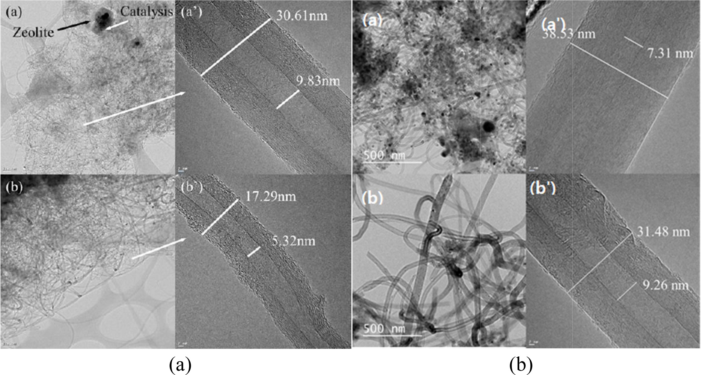
Fig. 16(a) shows the HRTEM images of multiwall CNTs
(MWCNTs) that were grown on (a) and (a,) Co-LTA-BCM and (b) and (b,)
Co-silicalite-1-BCM at 650 °C for 60 and 120 min, respectively. The CNTs in the
TEM image of Fig. 16(a) show small outer walls with a diameter of approximately
17.29 nm and an inner diameter of 5.32 nm. The outer walls
of the synthesized CNTs in Fig. 16(b) are comparatively thicker, and a
densely layered structure with outer and inner diameters
of approximately 30.61 and 9.83 nm, respectively, was formed. A base growth
mechanism can be clearly seen in the CNTs, which are known for better
attachment tendencies regarding the substrate. Also, note here the apparent
growth of the inner and outer diameters of the nanotubes.
Thus, it can be inferred that the decomposition of the
carbon atoms from C2H2, which formed a layered coaxial
cylindrical graphene sheet around the CNT core, is strongly related to the
reaction time and temperature. All of the CNT samples display a bamboo-like
structure and are typically MWCNTs. Moreover, it can be clearly inferred from
the following HRTEM images that the CNTs that were grown at 650 °C produced a
superior yield with smoother outer and inner walls, compared to the ones
synthesized at 700 °C [164, 165].
Figs. 16(b) and (b') show the HRTEM images of multi-walled
CNTs grown on Co-silicalite-1-BCM at 650 °C for (a) 60 min, and (b) 120
min, respectively. Fig. 16(b) shows thicker outer walls, with a diameter of
around 31.48 nm. with an inner diameter of 9.26 nm Also, note here the apparent
growth in terms of the inner and outer diameters. The synthesized CNTs at the
same temperature for 120 min shown in Fig. 16(b') have a comparatively thicker
outer wall, which forms a densely layered structure with an outer diameter of
around 38.53 nm and inner diameter of 7.31 nm. Moreover, it can clearly be
inferred from the HRTEM images below that the CNTs grown for 120 min have
better yield with smooth outer and inner walls, in comparison to the one
synthesized for 60 min [166].
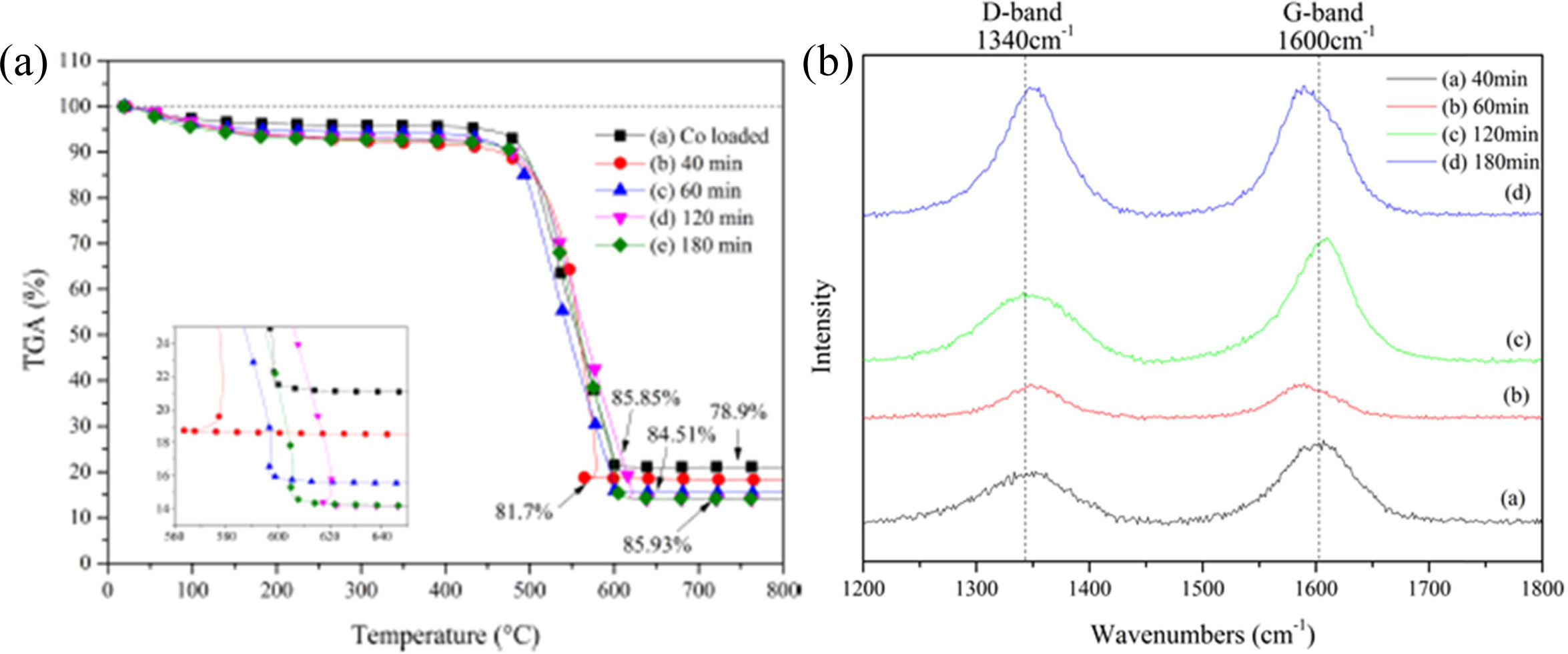
Fig. 17 shows the TGA curves of the CNTs grown on Co-LTA
BCM at 650 °C for (a) without CNTs, (b) 40 min, (c) 60 min, (d) 120 min, and
(e) 180 min, respectively. All samples represent an initial weight loss
tendency, which may occur through the loss of physically adsorbed water by the
zeolites until 195 °C. In the continuous increment of reaction time, all
samples undergo a weight loss pattern [165]. As compared with Fig. 17 (a), all
CNTs samples show a weight loss i.e. (b) 2.8 %, (c) 5.61 %, (d) 6.95 %, and (e)
7.03 %, respectively. These differences of weight loss can be explained by
carbon yield. The carbon yield from CNTs synthesized by metal containing CVD is
calculated as follows:
Carbon yield (%) = (mtot - mcat) / mcat × 100% (1)
where, mcat is the
initial catalyst amount (before reaction), and mtot
is the total sample weight after synthesis [166]. The TGA curves allow
estimation of the amount of carbon yield.
Fig. 17(b) shows the Raman spectra of the synthesized
CNTs. In these results, two strong peaks can be observed within the wavelengths
1,340 and 1,600 cm−1, designated as D- and G-bands, respectively.
These represent the presence of defects in the graphitic sheets, and
crystalline graphite carbon [166, 167]. The strength of the D-band relative to
the G-band is a measure of the amount of disorder in the CNTs and is used for
the qualitative analysis of nanotubes. The relative
intensities of the D- to G- bands (the ID/IG
ratio) revealed by the Raman spectroscopy is a measure of the degree of
graphitization. The ID/IG values are between 0.59 and
1.00, which is in accordance with those reported in the literature (ID/IG
= 0.7 ~ 1.3) for CVD grown MWCNTs [168, 169], revealing the
high-quality MWCNTs was grown.
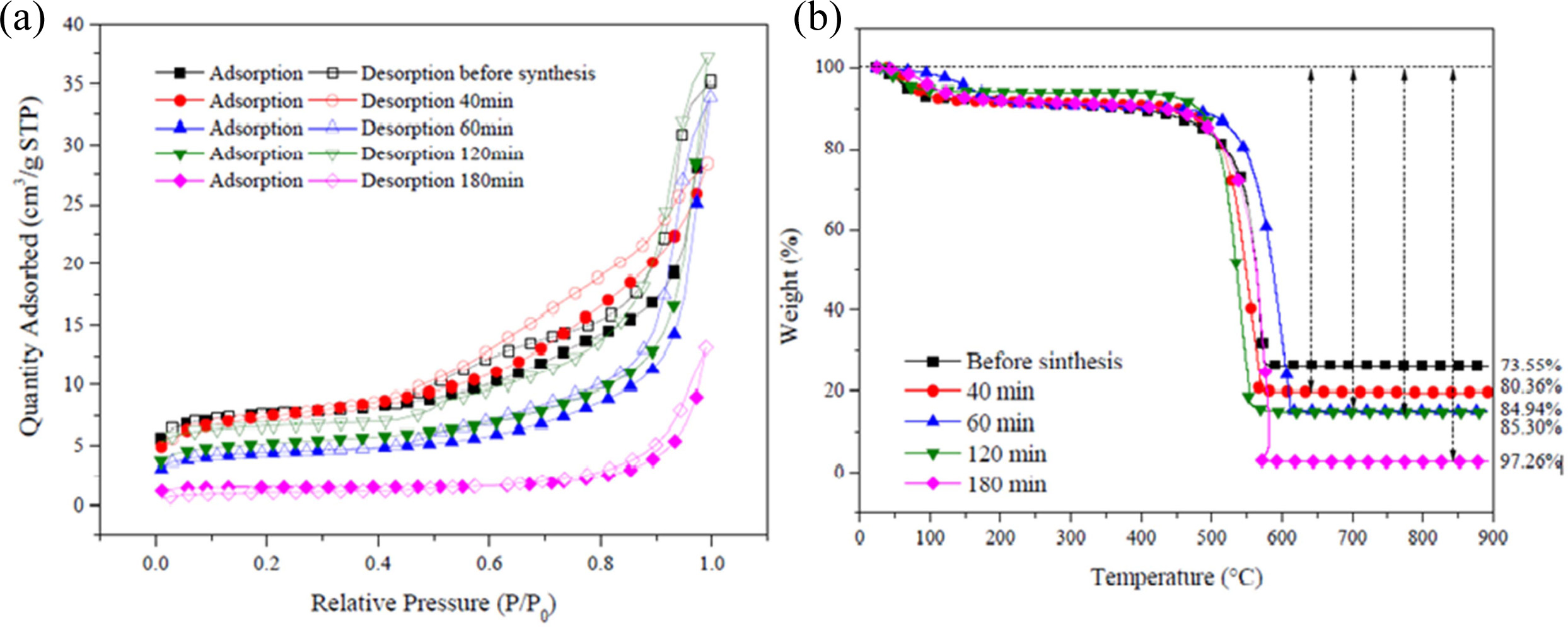
Fig. 18(a) shows the N2 adsorption/desorption
isotherms of Co-silicalite-1 BCM and CNTs grown at 650 °C for 40,
60, 120, and 180 min, respectively. The adsorption and desorption isotherms of
N2 for the Co loaded silicalite-1 on BCM and CNTs grown at
650 °C for (b) 40 min, (c) 60 min, (d) 120 min, and (e) 180 min are
clearly of type IV, according to the IUPAC classification
of adsorption isotherms. Type IV isotherms
characteristically show the simultaneous presence of micro- and mesopores. It
is evident that the adsorption capacities of CNTs were all increased with the
increase in reaction time [170-172]. All of the samples demonstrate
relatively high adsorption performance. Compared with Co-silicalited-1-BCM, the
adsorption capacity of CNTs silicalite-1 supported BCM is markedly
lower. For CNTs Co- silicalite-1-BCM, silicalite-1-BCM is the skeleton and is
coated on it, and then the silicalite-1 supported biomorphic carbon would be
the main adsorbent, as shown in Fig. 12(b).
Fig. 18(b) shows the TGA curves of the CNTs grown for 40,
60, 120, and 180 min at 650 °C, respectively. All CNTs samples represent an
initial weight loss tendency, which may occur through the loss of
physically adsorbed water by the silicalite-1 until 195 °C. In the subsequent heating
process, all samples undergo a two-step
weight loss pattern up to 97%. In the first step (458 ~ 633 °C
and 485 ~ 717 °C, respectively), the amorphous carbon has been combusted, while in the second step (≥ 633 and
717 °C, respectively), the MWCNTs have combusted until 800 °C.
After that, the samples maintain a weight loss pattern due
to biomorphic carbon combustion. The main reason for the
two-step pattern is that the decomposition of C2H2 on
metal catalysts leads to the formation of CNTs as amorphous carbon [173, 174].
All Raman spectra are dominated by two strong peaks at
1,340 and 1,620 cm-1.
The accepted terms for these two peaks are the D- and G-bands, respectively.
They are characteristic for disordered sp2-hybridised carbon
materials and have been observed in all reported Raman spectra of MWCNTs. The
D-band is formed by the defects in the graphite crystals, and by the finite
sizes of graphite crystallites in the material. Moreover, pyrolytic carbon
particles deposited on the nanotubes also contribute to the rise of D-band. The
G-band corresponds to the tangential stretching (E2g)
mode of highly oriented pyrolytic graphite (HOPG) and
indicates the presence of crystalline graphitic carbons in the MWCNTs. The
strength of the D-band relative to the G-band is a measure of the amount of
disorder in the CNTs and is used for qualitative characterizations of the
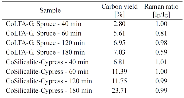
nanotubes [175, 176]. Table 3 shows the relative intensities of the D- to G-
bands (ID/IG ratio), as revealed by Raman spectroscopy, which
is a measure of the degree of graphitization. The carbon yield of 6.81 to
23.71% followed by BET ranging 4.31 to 22.24 m2/g was achieved with
the reaction time of 40 to 180 min, followed by the ID/IG
values from this work, which are between 0.99 and 1.01, which is
in accordance with that reported in the literature (ID/IG
= 0.97 ~ 1.00) for CVD-grown MWNTs [177, 178].
This finding can be attributed to the low permeability of
1.99 × 10⁻⁸ m2 compared to that of cypress
(Hinoki, 1.51 × 10⁻⁶ m2), which was tested
using Darcy’s law [179]. Table 4 summarizes the physical properties of the
Co-LTA and silicalite-1-BCM and CNTs grown at 650 °C for 40, 60, 120, and
180 min, such as carbon yield and Raman ratio.
|
Fig. 11 Process for synthesizing and coating LTA, silicalite-1 and mesoporous silica onto BCMs (Modified from ref. 156. Copyright 2018 Hanyang University). |
|
Fig. 12 FESEM images of cypress BCM coated with LTA (a), silicalite-1 (b), and mesoporous SiO2 (c) (Modified from ref. 156. Copyright 2018 Hanyang University). |
|
Fig. 13 XRD patterns (a) and N2-adsorption/desorption isotherms (b) of BCM coated with LTA, silicalite-1, and mesoporous silica [156] (Modified from ref. 156. Copyright 2018 Hanyang University). |
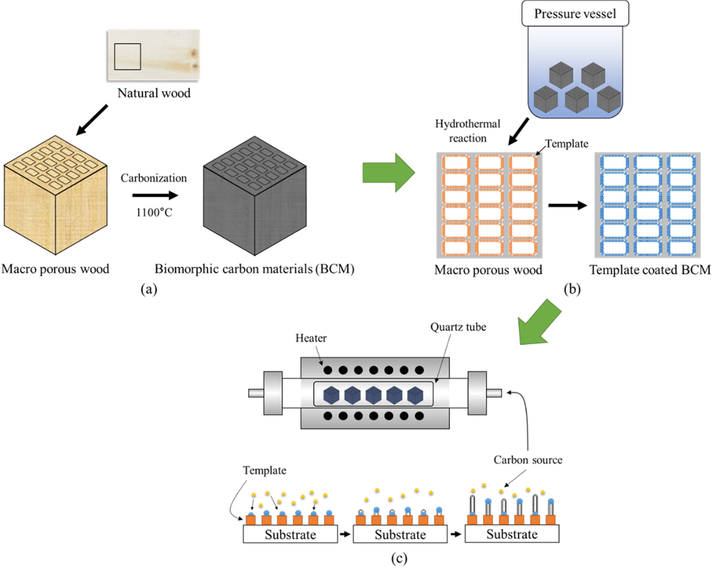
|
Fig. 14 Schematic diagram of growing Carbon nanotubes on BCM: Preparation of BCM (a), Template coating (b), and Carbon nanotube synthesis (c), respectively (Reproduced with permission from ref. 106. Copyright 2018 Inderscience Enterprises). |
|
Fig. 15 FESEM image of Co- catalyst loaded template coated BCM and synthesized CNTs (') on (a) LTA zeolite, (b) Silicalite-1, and (c) Mesoporous SiO2 template for 60 min at 650 oC. |
|
Fig. 16 HRTEM image of CNTs synthesis on Co-LTA(a) and Co-silicalite-1(b) coated BCM at 650 °C for (a) 60 min and (b) 120 min (Reproduced with permission from ref. 106. Copyright 2018 Inderscience Enterprises). |
|
Fig. 17 TGA curves (a) and Raman spectra (b) of CNTs synthesized on Co-LTA Gorman spruce BCM (Adapted from ref. 166. Copyright 2017 Hanyang University). |
|
Fig. 18 TGA curves(a) and BET surface area(b) of CNTs synthesis on silicalite-1 coated biomorphic carbon (Adapted from ref. 178. Copyright 2019 Hanyang University). |
|
Table 4 Quality of CNTs (Raman spectra) and Carbon Yield (TGA) with respect to the Reaction Time at 650 oC. |
Air and water pollution in industrial and metropolitan
areas is a threat to human health and natural resources, as millions of people
inhale polluted air, and particles in the air enter the body. Fine particles
can be trapped in the nostrils and can be in the hair at nano size below a
micron, but some fine particles can reach the lungs, and then remain in the lung cells,
causing serious diseases, such as lung
cancer or emphysema [180]. Clean air and water (no toxic chemicals and
pathogens) play a very important role in the human quality of life [181]. Water
and air are important sources of various food industries for maintaining good
health, including medicines [182]. In particular, it is difficult to remove
organisms such as bacteria and viruses from food, and much research is being carried out on the
contamination of inorganic substances
(e.g. heavy metal ions) from water, especially in the wastewater, metallurgy,
mining, and battery manufacturing industries [183]. Since these contaminants
can accumulate in living tissues, there is an increasing concern, and more
stringent regulations and standards for the discharge and removal of aquatic environments are being discussed. At present,
innovations and advances in
nanotechnology and nanomaterials can solve
many of the above-mentioned problems, in particular carbonaceous nanomaterial complexes. Individual
and bulk carbon-based nanomaterials have already paved the way for many
environmental applications. In particular, CNTs exhibit large absorption
properties, due to their high aspect ratio, and large specific surface area. They offer promise for applications in the
absorption, filtration, and
separation industries, in both gas and aqueous systems [180, 184].
- Air particulate filtration [185, 186]
- Biological contamination filtration [190, 191]
- Heavy metal ion adsorption [192, 193]
- Other applications [197, 198]
Air
particulate filtration
Heating, ventilation, and air conditioning (HVAC) filters
are ideal for dark, humid air cleaning. As conditions for bacteria
and malignant fungus, microorganisms become attached to the accumulated dust in
the filter, polluting the unpredictable air quality, as well as accumulating
the smell of dust in food. Nanofiber filter media are needed for
high-performance air purification, such as hospitals, medical facilities, and
laboratories [180]. In air filtration, especially in
laboratories, electronic component manufacturers, military
and government agencies, and food, pharmaceutical, and biotechnology companies,
contaminants are particles and mostly complex mixtures, which are generally
less than 1,000 μm in diameter [185]. Fiber filters are typically
fabricated from fibers with a diameter of about a few tens of micrometers,
which is a micrometer particle that enables high
efficiency removal of the sub-micrometer and has a relatively
low resistance to air flow. The filter is termed the most
penetrating particle size (MPPS), which is not as efficiently filtered as other
particles, and the fiber filter efficiency achieves the minimum value for this particle
size, which is generally between 0.1 and 0.5 μm [186, 187].
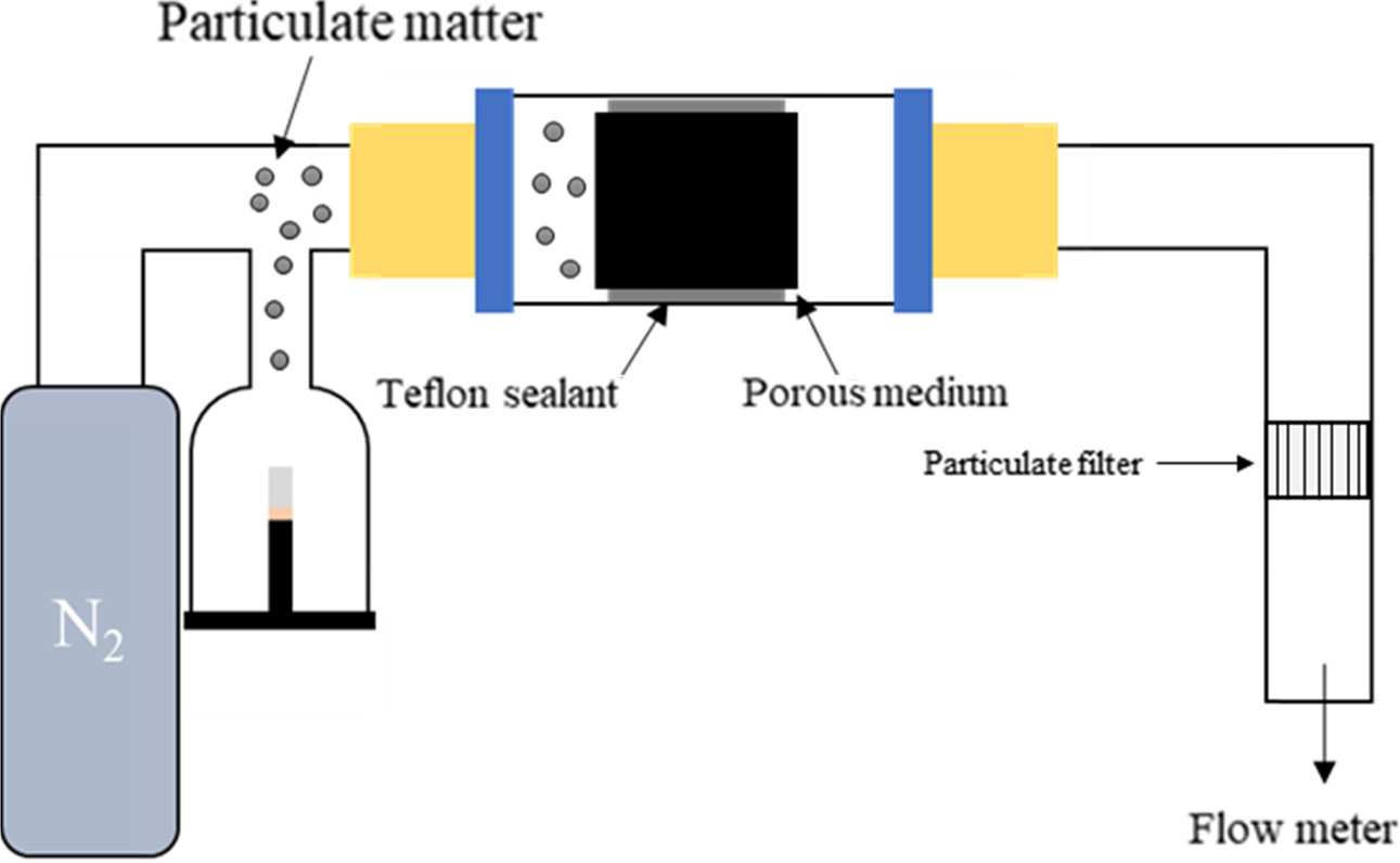
Park and Lee [188] grew CNTs 20 ~ 50 nm diameter using the CVD method
on micron-sized stainless steel fibers and evaluated the performance of air
particulate removal using sodium chloride (NaCl) as test particles, as shown in
Fig. 19. Web-like CNTs were fabricated to improve the efficiency from 75 to
98%. Park’s group reported similar results using fiberglass [189].
Biological
contamination filtration
Biological contaminants make up a significant portion of
drinking water, in terms of the number of pollutants
and the treatment probability. High-efficiency filtration
of contaminants is performed using ceramic or metal
membranes [180, 190]. The polymer membrane is fragile
and durable. In conventional membrane filters used for water filtration, the
adsorption of bacteria on the surface affects the physical
properties and is difficult to reuse. The use of CNTs in
membranes is also an effective way to create a practical hybrid filter with
excellent robustness for reuse. With high surface area and large aspect ratio,
high-density coagulated packed CNTs form a microporous and
mesoporous network with an appropriate pore size, which
adsorbs contaminants through physisorption [191, 192]. In
addition, the toxicity of microbial cells also plays a part
in the filtration performance of CNTs. The stability of CNTs at high temperatures
enables higher operating temperatures up to 400 °C. Compared with
conventional polymer membrane filters up to 52 °C,
these filters are very good, and for their reuse, simple filter
cleaning is sufficient for ultrasonication and autoclaving sterilization up to
121 °C for 30 minutes. Brady-Estevez et al. increased filter permeability by
immobilizing CNTs deposited on microporous ceramic filters with 5 µm pore size.
They demonstrated a filter to remove viral and bacterial pathogens
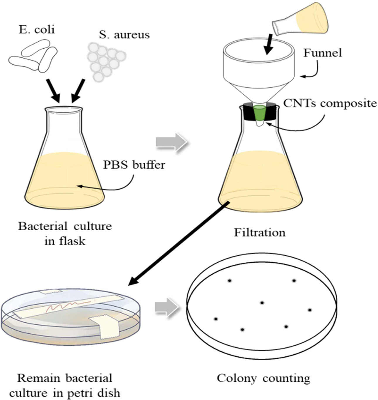
with very high efficiency [193]. Akasaka and Watari have
shown that moderately flexible SWCNTs and MWCNTs can be easily wound around the
curved surface of Streptococcus mutans, and used as a tool to remove nano-level
oral pathogens, as shown in Fig. 20 [194]. First, the CNTs was
dispersed in a solution containing bio-contaminants, the suspension was shaken
for a long time to achieve complete adsorption, and then the CNTs was removed
using a paper filter or a suitable membrane.
Heavy
metal ion adsorption
Water pollution caused by indiscriminate disposal of metal
ions has attracted worldwide attention [197]. In this regard, a number of
studies have attempted to use CNTs to remove such contaminants from wastewater.
Contaminants include Cu, Pb, Cd [195], Zn, Mn, Co [196], Ni [297], Cr [198], Hg
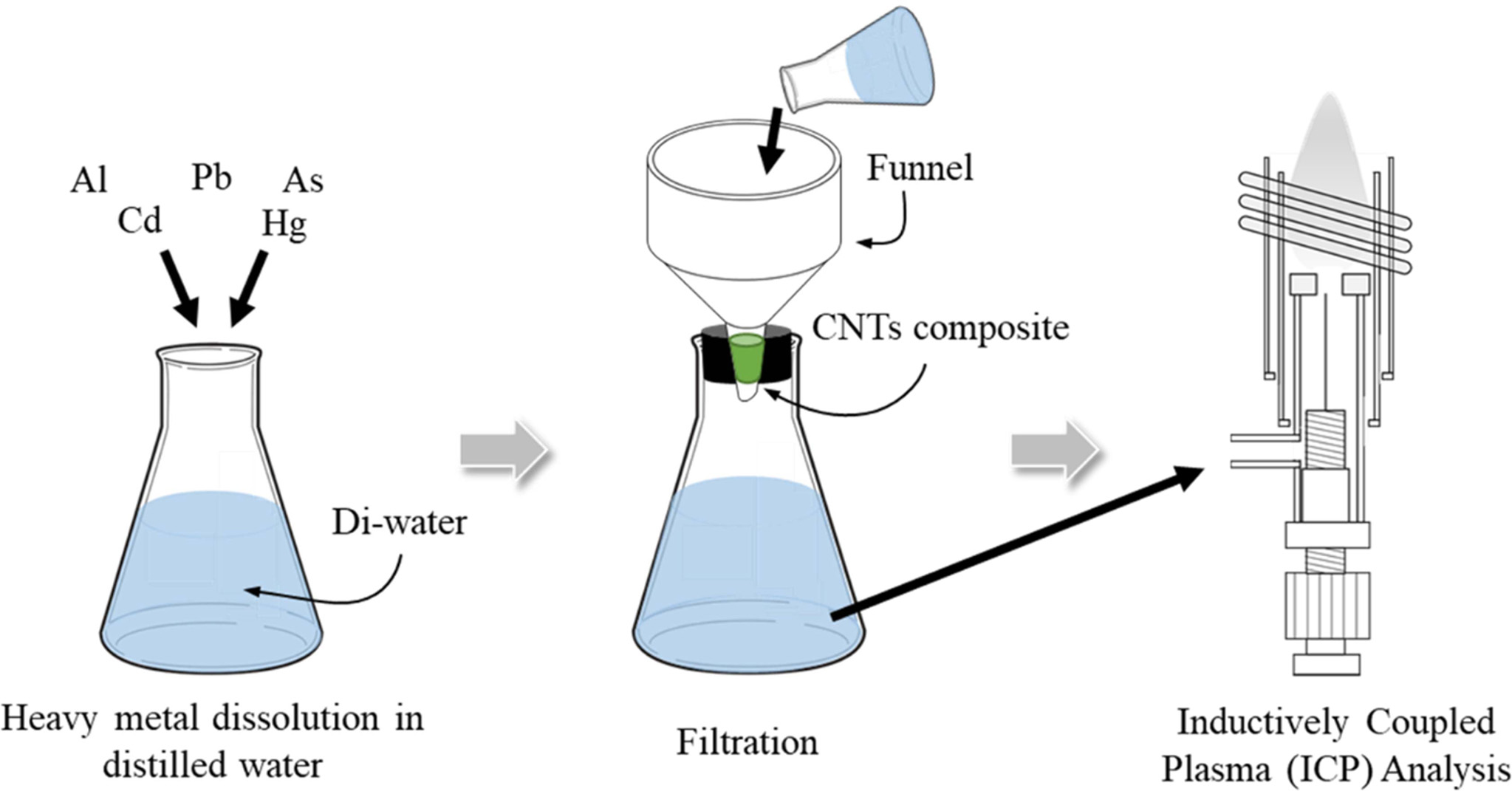
[199], and U [200] ions. Figure 21 shows that the adsorption mechanism of heavy
metals by CNTs is a chemisorption process. The chemical interaction between
metal ions and metal ions is dominated by the surface functionalities of CNTs formed
during oxidation rather than physical adsorption, which is
compared to electrostatic attraction and adsorption-precipitation
[201]. As a result, the chemical and thermal
treatments during the functionalization process have a leading influence on the
performance of CNTs for metal ion removal, and the adsorption
behavior is mainly determined by the nature and concentration of
the adsorbent surface functional group. Other terms and aspects of heavy metal
ion adsorption through CNTs synthesized and functionalized with different
adsorption capacities and different carbon sources and catalysts include
effective parameters. For example, increasing adsorption
temperatures result in a significant increase in adsorption
capacity [202, 203]. This is an endothermic reaction. As the mass of CNTs
increases, the adsorption rate of the metal increases. This is limited to a
certain value with an increase in the number of adsorption sites.
Other
applications
There are many other reports that have shown the
successful use of CNTs in filtering applications [180]. Sponges have been
successfully synthesized with CNTs by Gui et al., and could
clearly reflect the large adsorption properties of
these carbon clusters [204]. They produced
self-assembled and interconnected carbon nanotube backbone sponge-like bulk
materials close to airgels with > 99 % porosity and light density. Lee and
Baik also produced nanotube membrane filters that can affect the phase
separation of diesel and aqueous layers, surfactant stabilized emulsions, high
viscosity lubricants, and water emulsions [205]. They deposited a mesh-on-mesh
using an electron beam evaporator and made a filter on a
stainless-steel mesh using a sandwich type iron catalyst layer,
followed by a CVD process. Mainstream smoke (MS), published by Chen et al., has
a very high adsorption capacity of oxidized CNTs (O-CNTs) to nicotine and tar,
and adds about (20 ~ 30) mg to the filter tip of tobacco, to prevent
the influx of harmful substances [206].
|
Fig. 19 Schematic diagram of air filter evaluation of CNTs nanofilter. |
|
Fig. 20 Schematic of biological contamination filtration of CNTs nanofilter. |
|
Fig. 21 Schematic of the heavy-metal adsorption of CNTs nanofilter. |
The unique properties of CNTs, including high surface area
and strong Van der Waals forces at high aspect ratios, make them exceptional in
their ability to filter organic and inorganic contaminants on a
molecular basis. In particular, they exhibit a variety of
processing capacities to trap and fix contaminants in the pores of individual
CNTs during flocculation, and also to trap large-scale
pore-sized mesoporous networks with biological contaminants, such as bacteria
and viruses. A wide range of pore formation through the combination of CNTs and
porous ceramics can be advantageously used as a filter for gas through
physisorption. In particular, since the cytotoxicity of CNTs in microbial
treatment partially affects the filtration performance, an approach that can be
effectively applied in water as well as atmospheric filtration devices has been
studied. In this review, carbon nanotubes (CNTs) synthesized on metal-supported
template (LTA, silicalite-1, mesoporous SiO2 etc.) coated biomorphic
carbon materials (BCM) were achieved with both high quality, and high yield of carbons.
The amounts of MWCNTs were formed by the combination
of three different novel processing routes. Because of the uniform pore
structure, the template crystals can be located all over the BCM surface. Also,
owing to the high porosity template crystals, the acetylene
can supply carbon source to the catalytic metal nanoparticles
appropriately, to lead the growth of CNTs across the entire template. The
morphology of CNTs was influenced by reaction temperature. The
microstructure obtained at 700 °C exhibited
considerable wall thickness, and the widest inner hollow tube
structure; whereas that of CNTs obtained at 650 °C shows comparability thinner
outer wall and narrow inner hole. The maximum yield of
carbon was 23.71% at 650 oC for 180 min, but on comparison with
the Raman ratio, the synthesized CNTs were found to have better quality at (60
to 120) min, with a moderate yield of carbon. The ID/IG
ratio of Co-silicalite-1-BCM from Raman analysis was found between 0.97 and
1.00, which is in accordance with those reported in the Co-LTA-BCM for
CVD-grown MWNTs. Furthermore, the synthesized CNTs filter can be applied as a
filter for removing various pollutants. Especially, the filters are expected to
be used in HVAC, water quality and air purification through performance evaluation
such as air particulate, biological contamination and heavy
metal filtration.
This research was supported by the Basic Science Research
Program through the National Research Foundation of Korea (NRF), funded by the
Ministry of Education (201800790001) and special thanks for analysis support
and biomorphic carbon materials from Korea Institute of Energy Research (KIER).
- 1. F.S. Rojas, C.B. Ojeda, and J.M.C. Pavón, Am. J. Anal. Chem. 2[1] (2011) 66-74.
-

- 2. A. Zampieri, H. Sieber, T. Selvam, G.T. Mabande, W. Schwieger, F. Scheffler, M. Scheffler, and P. Greil, Adv. Mater. 17[3] (2005) 344-349.
-
- 3. Y. Shen, J. Agric. Food. Chem. 65[5] (2017) 995-1004.
-
- 4. S.Y. Kim, H.U. Kim, Y.H. Seong, I.S. Han, S.K. Woo, and S.H. Kim, J. Porous Mater. 25[2] (2018) 603-609.
-
- 5. J.G. Park, S.Y. Kim, Z. Wei, J.H. Jeon, S.Y. Kim, and I.J. Kim, J. Ceram. Proc. Res. 18[2] (2017) 161-165.
- 6. J. Li, Q. Xu, J. Wang, J. Jiao, and Z. Zhang, Ind. Eng. Chem. Res. 47[20] (2008) 7680-7685.
-
- 7. K.B. Choi, J.Y. Kim, S.M. Lee, K.H. Lee, and D.H. Yoon, J. Korean Ceram. Soc. 54[3] (2017) 257-260.
-
- 8. W. Zhao, B. Basnet, and I.J. Kim, J. Adv. Ceram. 1[3] (2012) 179-193.
-
- 9. S. Iijima and T. Ichihashi, Nat. 363[6430] (1993) 603-605.
-
- 10. C. Yu, L. Shi, Z. Yao, D. Li, and A. Majumdar, Nano. Lett. 5[9] (2005) 1842-1846.
-
- 11. K. Lee, S.Y. Shin, and Y.S. Yoon, J. Korean Ceram. Soc. 53[3] (2016) 376-380.
-
- 12. Y.L. Kim, J. Korean Ceram. Soc. 54[1] (2017) 66-69.
-
- 13. J. K. Holt, H. G. Park, Y. Wang, M. Stadermann, A. B. Artyukhin, C. P. Grigoropoulos, A. Noy, and O. Bakajin, Science 312[5776] (2006) 1034-1037.
-
- 14. Y. Zhao, H. Nakano, H. Murakami, T. Sugai, H. Shinohara, and Y. Saito, Appl. Phys. A. 85[2] (2006) 103-107.
-
- 15. V.K.K. Upadhyayula, S. Deng, M.C. Mitchell, and G.B. Smith, Sci. Total. Environ. 408[1] (2009) 1-13.
-
- 16. A.S. Brady-Estévez, S. Kang, and M. Elimelech, Small 4[4] (2008) 481-484.
-
- 17. A. Stafiej and K. Pyrzynska, Sep. Purif. Technol. 58[1] (2007) 49-52.
-
- 18. Y.H. Li, J. Ding, Z. Luan, Z. Di, Y. Zhu, C. Xu, D. Wu, and B. Wei, Carbon 41[14] (2003) 2787-2792.
-
- 19. Y.H. Li, Y.M. Zhao, W.B. Hu, I. Ahmad, Y.Q. Zhu, X.J. Peng, and Z.K. Luan, J. Phys. Conf. Series. 61 (2007) 698-702.
-
- 20. A. Srivastava, O.N. Srivastava, S. Talapatra, R. Vajtai, and P.M. Ajayan, Nat. Mater. 3[9] (2004) 610-614.
-
- 21. N. Halonen, A. Rautio, A.R. Leino, T. Kyllonen, G. Toth, J. Lappalainen, K. Kordas, M. Huuhtanen, R.L. Keiski, A. Sapi, M. Szabo, A. Kukovecz, Z. Konya, I. Kiricsi, P.M. Ajayan, and R. Vajtai, ACS. Nano 4[4] (2010) 2003-2008.
-
- 22. P.M. Ajayan, Chem. Rev. 99[7] (1999) 1787-1800.
-
- 23. W.Z. Li, J.G. Wen, Y. Tu, and Z.F. Ren, Appl. Phys. 73[2] (2001) 259-264.
-
- 24. D.J. Kim, S.M. Jeong, S.G. Yoon, C.H. Woo, J.I. Kim, H.G. Lee, J.Y. Park, and W.J. Kim J. Korean Ceram. Soc. 53[6] (2016) 597-603.
-
- 25. C. Weilach, C. Spiel, K. Föttinger, and G. Rupprechter, Surf. Sci. 605[15] (2011) 1503-1509.
-
- 26. K. An, N. Musselwhite, G. Kennedy, V.V. Pushkarev, L.R. Baker, and G.A. Somorjai, J. Colloid Interface Sci. 392 (2013) 122-128.
-
- 27. Y.M. Kim and I.J. Kim, J. Korean Ceram. Soc. 43[1] (2006) 1-3.
-
- 28. S.J. Park and D.G. Lee, Curr. Appl. Phys. 6[S1] (2006) e182-e186.
-
- 29. W. Zhao, S.D. Nam, A. Pokhrel, J. Gong, and I.J. Kim, J. Korean Ceram. Soc. 50[1] (2013) 1-17.
-
- 30. I.J. Kim, W. Zhao, X. Fan, J.H. Chang, and L.J. Gauckler, J. Ceram. Proc. Res. 11[2] (2010) 158-163.
- 31. Y. Yang, Z. Hu, Y.N. Lü, and Y. Chen, Mater. Chem. Phys. 82[2] (2003) 440-443.
-
- 32. K.S. Novoselov, A.K. Geim, S.V. Morozov, D. Jiang, Y. Zhang, S.V. Dubonos, I.V. Grigorieva, and A.A. Firsov, Science 306[5696] (2004) 666-669.
-
- 33. S. lijima and T. Ichihashi, Nat. 364[6439] (1993) 737-737.
-
- 34. K.W. Kolasiniski, in “Surface Science: Foundations of Catalysis and Nanoscience” (Wiely, 2012) p. 18.
-
- 35. A.P. Graham, G.S. Duesberg, W. Hoenlein, F. Kreupl, M. Liebau, R. Martin, B. Rajasekharan, W. Pamler, R. Seidel, W. Steinhoegl, and E. Unger, Appl. Phys. A. 80[6] (2005) 1141-1151.
-
- 36. R. Saito, in “Physical Properties of Carbon Nanotubes” (World Scientific Publishing Company, 1998) p. 36.
-
- 37. G.D. Nessim, Nanoscale. 2[8] (2010) 1306-1323.
-
- 38. D. Dass, R. Prasher, and R. Vaid, Int. J. Comput. Eng. Res. 2[5] (2012) 1447-1457.
- 39. Z. Xu, X. Bai, Z. L. Wang, and E. Wang, J. Am. Chem. Soc. 128[4] (2006) 1052-1053.
-
- 40. H.W. Zhu, C.L. Xu, D.H. Wu, B.Q. Wei, R. Vajtai, and P.M. Ajayan, Science 296[5569] (2202) 884-886.
-
- 41. H. Kataura, Y. Kumazawa, Y. Maniwa, I. Umezu, S. Suzuki, Y. Ohtsuka, and Y. Achiba, Synth. Met. 103[1] (1999) 2555-2558.
-
- 42. B.I. Kharisov. O.V. Kharissova, and U. Ortiz-Mendez, in “Handbook of Less-Common Nanostructures” (CRC Press, 2012) p. 31.
-
- 43. P.G. Collins, A. Zettl, H. Bando, A. Thess, and R.E. Smalley, Science 278[5335] (1997) 100-102.
-
- 44. M. Nihei, A. Kawabata, D. Kondo, M. Horibe, S. Sato, and Y. Awano, Jpn. J. Appl. Phys. 44[4A] (2005) 1626-1628.
-
- 45. R.H. Baughman, C. Cui, A.A. Zakhidov, Z. Iqbal, J.N. Barisci, G.M. Spinks, G.G. Wallace, A. Mazzoldi, D.D. Rossi, A.G. Rinzler, O. Jaschinski, S. Roth, and M. Kertesz, Science 284[5418] (1999) 1340-1344.
-
- 46. C. Liu, Y.Y. Fan, M. Liu, H.T. Cong, H.M. Cheng, and M.S. Dresselhaus, Science 286[5442] (1999) 1127-1129.
-
- 47. C. Liu, Y. Tong, H.M. Cheng, D. Golberg, and Y. Bando, Appl. Phys. Lett. 86[22] (2005) 223114.
-
- 48. J. Kong, E. Yenilmez, T.W. Tombler, W. Kim, H. Dai, R.B. Laughlin, L. Liu, C.S. Jayanthi, and S.Y. Wu, Phys. Rev. Lett. 87[10] (2001) 106801.
-
- 49. C. Zhou, J. Kong, and H. Dai, Appl. Phys. Lett. 76[12] (2000) 1597-1599.
-
- 50. D. Yokoyama, T. Iwasaki, K. Ishimaru, S. Sato, T. Hyakushima, M. Nihei, Y. Awano, and H. Kawarada, Jpn. J. Appl. Phys. 47[4] (2008) 1985-1990.
-
- 51. A. Javey, J. Guo, Q. Wang, M. Lundstrom, and H. Dai, Nat. 424 (2003) 654-657.
-
- 52. P.G. Collins, M.S. Arnold, and P. Avouris, Science 292[5517] (2001) 706-709.
-
- 53. S. Frank, P. Poncharal, Z.L. Wang, and W.A. Heer, Science 280[5370] (1998) 1744-1746.
-
- 54. A. Naeemi and J.D. Meindl, IEEE Electron. Device. Lett. 27[5] (2006) 338-340.
-
- 55. H.J. Li, W.G. Lu, J.J. Li, X.D. Bai, and C.Z. Gu, Phys. Rev. Lett. 95[8] (2005) 086601.
-
- 56. J.P. Lu, Phys. Rev. Lett. 79[7] (1997) 1297-1300.
-
- 57. J.P. Salvetat, J.M. Bonard, N.H. Thomson, A.J. Kulik, L. Forró, W. Benoit, and L. Zuppiroli, Appl. Phys. A. 69[3] (1999) 255-260.
-
- 58. M.F. Yu, B.S. Files, S. Arepalli, and R.S. Ruoff, Phys. Rev. Lett. 84[24] (2000) 5552-5555.
-
- 59. N. Yao, and V. Lordi, J. Appl. Phys. 84[4] (1998) 1939-1943.
-
- 60. G. Zhou, W. Duan, and B. Gu, Chem. Phys. Lett. 333[5] (2001) 344-349.
-
- 61. Z. Yao, C.C. Zhu, M. Cheng, and J. Liu, Comput. Mater. Sci. 22[3] (2001) 180-184.
-
- 62. B.G. Demczyk, Y.M. Wang, J. Cumings, M. Hetman, W. Han, A. Zettl, and R.O. Ritchie, Mater. Sci. Eng. A. 334[1] (2002) 173-178.
-
- 63. J. Hone, M. Whitney, and A. Zettl, Synth. Met. 103[1] (1999) 2498-2499.
-
- 64. E. Pop, D. Mann, Q. Wang, K. Goodson, and H. Dai, Nano. Lett. 6[1] (2006) 96-100.
-
- 65. P. Kim, L. Shi, A. Majumdar, and P.L. McEuen, Phys. Rev. Lett. 87[21] (2001) 215502.
-
- 66. R.H. Fowler and L. Nordheim, Proc. R. Soc. London. Ser. A. 119[781] (1928) 173-181.
-
- 67. S. Fan, M.G. Chapline, N.R. Franklin, T.W. Tombler, A.M. Cassell, and H. Dai, Science 283[5401] (1999) 512-514.
-
- 68. H. Zhu, J. Wei, K. Wang, and D. Wu, Sol. Energy Mater. Sol. Cells 93[9] (2009) 1461-1470.
-
- 69. E. Kymakis, I. Alexandrou, and G.A.J. Amaratunga, J. Appl. Phys. 93[3] (2003) 1764-1768.
-
- 70. A. Kongkanand, R.M. Domínguez, and P.V. Kamat, Nano. Lett. 7[3] (2007) 676-680.
-
- 71. C. Journet, W.K. Maser, P. Bernier, A. Loiseau, M.L. de la Chapelle, S. Lefrant, P. Deniard, R. Lee, and J.E. Fischer, Nat. 388 (1997) 756-758.
-
- 72. Y. Saito, K. Nishikubo, K. Kawabata, and T. Matsumoto, J. Appl. Phys. 80[5] (1996) 3062-3067.
-
- 73. W. Krätschmer, L.D. Lamb, K. Fostiropoulos, and D.R. Huffman, Nat. 347[6291] (1990) 354-358.
-
- 74. B.I. Yakobson and R.E. Smalley, Am. Sci. 85[4] (1997) 324-337.
- 75. T. Guo, P. Nikolaev, A. Thess, D.T. Colbert, and R.E. Smalley, Chem. Phys. Lett. 243[1] (1995) 49-54.
-
- 76. A.G. Rinzler, J. Liu, H. Dai, P. Nikolaev, C.B. Huffman, F.J. Rodríguez-Macías, P.J. Boul, A.H. Lu, D. Heymann, D.T. Colbert, R.S. Lee, J.E. Fischer, A.M. Rao, P.C. Eklund, and R.E. Smalley, Appl. Phys. A. 67[1] (1998) 29-37.
-
- 77. Y. Zhang and S. Iijima, Appl. Phys. Lett. 75[20] (1999) 3087-3089.
-
- 78. W. Zhao, D.N. Seo, H.T. Kim, and I. J. Kim, J. Ceram. Soc. Jpn. 118[1383] (2010) 983-988.
-
- 79. K.P. De Jong, and J.W. Geus, Catal. Rev. 42[4] (2000) 481-510.
-
- 80. Z.F. Ren, Z.P. Huang, D.Z. Wang, J.G. Wen, J.W. Xu, J.H. Wang, L.E. Calvet, J. Chen, J.F. Klemic, and M.A. Reed, Apply. Phys. Lett. 75[8] (1999) 1086-1088.
-
- 81. Z.F. Ren, Z.P. Huang, J.W. Xu, J.H. Wang, P. Bush, M.P. Siegal, and P.N. Provencio, Science 282[5391] (1998) 1105-1107.
-
- 82. Z.P. Huang, J.W. Xu, Z.F. Ren, J.H. Wang, M.P. Siegal, and P.N. Provencio, Appl. Phys. Lett. 73[26] (1998) 3845-3847.
-
- 83. E.T. Thostenson, Z. Ren, and T.W. Chou, Compos. Sci. Technol. 61[13] (2001) 1899-1912.
-
- 84. J. Kong, A.M. Cassell, and H. Dai, Chem. Phys. Lett. 292[4] (1998) 567-574.
-
- 85. J.H. Hafner, M.J. Bronikowski, B.R. Azamian, P. Nikolaev, A.G. Rinzler, D.T. Colbert, K.A. Smith, and R.E. Smalley, Chem. Phys. Lett. 296[1] (1998) 195-202.
-
- 86. M. Sarikaya and I.A. Aksay, Mater. Res. Soc. Symp. Proc. 255 (1992) 293-307.
-
- 87. P. Calvert, MRS Bull. 17[10] (2013) 37-40.
- 88. M. Sarikaya, Microsc. Res. Tech. 27[5] (1994) 360-375.
-
- 89. J.E. Mark and P.D. Calvert, Mater. Sci. Eng. C. 1[3] (1994) 159-173.
-
- 90. C.E. Byrne and D.C. Nagle, Carbon 35[2] (1997) 259-266.
-
- 91. E. Auer, A. Freund, J. Pietsch, and T. Tacke, Appl. Catal. A. 173[2] (1998) 259-271.
-
- 92. J.M. Gatica, A.L. García-Cabeza, M.P. Yeste, R. Marín-Barrios, J.M. González-Leal, G. Blanco, G.A. Cifredo, F.M. Guerra, and H. Vidal, Chem. Eng. J. 209[15] (2016) 174-184.
-
- 93. T.X. Fan, T. Hirose, T. Okabe, and D. Zhang, J. Porous Mater. 8[3] (2001) 211-217.
-
- 94. D. Mohan, C.U. Pittman, M. Bricka, F. Smith, B. Yancey, J. Mohammad, P.H. Steele, M.F. Alexandre-Franco, V. Gómez-Serrano, and H. Gong, J. Colloid Interface Sci. 310[1] (2007) 57-73.
-
- 95. Y. Yao, B. Gao, H. Chen, L. Jiang, M. Inyang, A.R. Zimmerman, X. Cao, L. Yang, Y. Xue, and H. Li, J. Hazard. Mater. 209 (2012) 408-413.
-
- 96. D.C. Cruz, in “Production of Bio-coal and Activated Carbon from Biomass” (University of Western Ontario, 2012) p. 20.
- 97. R. Beigmoradi, A. Samimi, and D. Mohebbi-Kalhori, Beilstein. J. Nanotechnol. 9 (2018) 415-435.
-
- 98. K.W. Brown, B. Gessesse, L.J. Butler, and D.L. Maclntosh, Environ. Health Insights. 11 (2017) 1-8.
-
- 99. J. Ramírez-Rico, J. Martínez-Fernandez, and M. Singh, Int. Mater. Rev. 62[8] (2017) 465-485.
-
- 100. M.H. Ramage, H. Burridge, M. Busse-Wicher, G. Fereday, T. Reynolds, D.U. Shah, G. Wu, L. Yu, P. Fleming, D. Densley-Tingley, J. Allwood, P. Dupreee, P.F. Linden, and O. Scherman, Renewable Sustainable Energy Rev. 68[1] (2017) 333-359.
-
- 101. A.J. Panshin and C.D. Zeeuw, in “Textbook of wood technology: structure, identification, properties, and uses of the commercial woods of the United States and Canada” (McGraw-Hill, 1980) p. 83.
- 102. L.J. Gibson and M.F. Ashby, in “Cellular Solids: Structure and Properties” (Cambridge University Press, 1999) p. 415.
- 103. R.F. Evert and S.E. Eichhorn in “Esau's Plant Anatomy: Meristems, Cells, and Tissues of the Plant Body: Their Structure, Function, and Development” (Wiley, 2006) p. 296.
- 104. J.M. Dinwoodie, in “Wood, nature's cellular, polymeric, fibre-composite” (Institute of Metals, 1989) p. 37.
- 105. H. Yang, R. Yan, H. Chen, D.H. Lee, and C. Zheng, Fuel 86[12] (2007) 1781-1788.
-
- 106. J.G. Park, S.Y. Kim, I.S. Han, S.S. Ryu, and I.J. Kim, Int. J. Nanotechnol. 15[6-7] (2018) 460-473.
-
- 107. P. Gao, Y. Bai, S. Lin, W. Guo, and H. Xiao, Ceram. Int. 34[8] (2008) 1975-1981.
-
- 108. Y.M. Chiang, R.P. Messner, C.D. Terwilliger, and D.R. Behrend, Mater. Sci. Eng. A. 144[1] (1991) 63-74.
-
- 109. P. Greil, T. Lifka, and A. Kaindl, J. Eur. Ceram. Soc. 18[14] (1998) 1975-1983.
-
- 110. P. Greil, E. Vogli, T. Fey, A. Bezold, N. Popovska, H. Gerhard, and H. Sieber, J. Eur. Ceram. Soc. 22[14] (2002) 2697-2707.
-
- 111. M. Singh and D.R. Behrendt, J. Mater. Res. 9[7] (2011) 1701-1708.
-
- 112. M. Singh and D. R. Behrendt, Mater. Sci. Eng. A. 194[2] (1995) 193-200.
-
- 113. A. Wolfenden, P.J. Rynn, and M. Singh, J. Mater. Sci. 30[21] (1995) 5502-5507.
-
- 114. F. Gutierrez-Mora, K.C. Goretta, F.M. Varela-Feria, A.R.A. López, and J.M. Fernández, Int. J. Refract. Met. Hard. Mater. 23[4] (2005) 369-374.
-
- 115. M. Presas, J.Y. Pastor, J. Llorca, A.R.A. López, J.M. Fernández, and R.E. Sepúlveda, Int. J. Refract. Met. Hard. Mater. 24[1] (2006) 49-54.
-
- 116. M. Presas, J.Y. Pastor, J. Llorca, A.R.A. López, J.M. Fernández, and R.E. Sepúlveda, Scripta. Mater. 53[10] (2005) 1175-1180.
-
- 117. M. Presas, J. Pastor, J. Llorca, A. Ramirez de Arellano Lopez, J. Fernández, and R. Sepúlveda Ferrer, Bol. Soc. Esp. Ceram. Vidrio. 44[6] (2005) 363-367.
-
- 118. D.J. Lee, J.J. Jang, H.S. Park, Y.C. Kim, K.H. Lim, S.B. Park, and S.H. Hong, Ceram. Int. 38[4] (2012) 3089-3095.
-
- 119. G. Hou, Z. Jin, and J. Qian, Mater. Sci. Eng. A. 452[15] (2007) 278-283.
-
- 120. V.S. Kaul, K.T. Faber, R. Sepúlveda, A.R.A. López, and J.M. Fernández, Mater. Sci. Eng. A. 428[1] (2006) 225-232.
-
- 121. H. Ago, S. Imamura, T. Okazaki, T. Saito, M. Yumura, and M. Tsuji, J. Phys. Chem. B. 109[20] (2005) 10035-10041.
-
- 122. K. Hata, D.N. Futaba, K. Mizuno, T. Namai, M. Yumura, and S. Iijima, Science 306[5700] (2004) 1362-1364.
-
- 123. R. Andrews, D. Jacques, A.M. Rao, F. Derbyshire, D. Qian, X. Fan, E.C. Dickey, and J. Chen, Chem. Phys. Lett. 303[5] (1999) 467-474.
-
- 124. B. Kitiyanan, W.E. Alvarez, J.H. Harwell, and D.E. Resasco, Chem. Phys. Lett. 317[3] (2000) 497-503.
-
- 125. D. Ding, J. Wang, Z. Cao, and J. Dai, Carbon 41[3] (2003) 579-582.
-
- 126. C.L. Cheung, A. Kurtz, H. Park, and C.M. Lieber, J. Phys. Chem. B. 106[10] (2002) 2429-2433.
-
- 127. I. Willems, Z. Kónya, J.F. Colomer, G.V. Tendeloo, N. Nagaraju, A. Fonseca, and J.B. Nagy, AIP. Conf. Proc. 544[1] (2000) 242-245.
- 128. M. Kumar, and Y. Ando, Carbon 43[3] (2005) 533-540.
-
- 129. J.W. Ward, B.Q. Wei, and P.M. Ajayan, Chem. Phys. Lett. 376[5] (2003) 717-725.
-
- 130. M. Karthik, A. Vinu, A.K. Tripathi, N.M. Gupta, M. Palanichamy, and V. Murugesan, Microporous Mesoporous Mater. 70[1] (2004) 15-25.
-
- 131. M. Kumar and Y. Ando, J. Nanosci. Nanotechnol. 10 (2010) 3739-3758.
-
- 132. Y.R. Son, M.K. Kim, S.G. Ryu, and H.S. Kim, ACS. Appl. Mater. Interfaces 10[47] (2018) 40651-40660.
-
- 133. S.J. Datta, C. Khumnoon, Z.H. Lee, W.K. Moon, S. Docao, T.H. Nguyen, I.C. Hwang, D. Moon, P. Oleynikov, O. Terasaki, and K.B. Yoon, Science 350[6258] (2015) 302-306.
-
- 134. D.H. Lee, and H.S. Kim, Appl. Catal. A. 574 (2019) 71-78.
-
- 135. B.M. Weckhuysen and J. Yu, Chem. Soc. Rev. 44[20] (2015) 7022-7024.
-
- 136. H.S. Kim and K.B. Yoon, Coord. Chem. Rev. 263[15] (2014) 239-256.
-
- 137. G.S. Lee, Y.J. Lee, and K.B. Yoon, J. Am. Chem. Soc. 123[40] (2001) 9769-9779.
-
- 138. G. Calzaferri, M. Pauchard, H. Maas, S. Huber, A. Khatyr, and T. Schaafsma, J. Mater. Chem. 12[1] (2002) 1-13.
-
- 139. K. Ha, Y.J. Lee, D.Y. Jung, J.H. Lee, and K.B. Yoon, Adv. Mater. 12[21] (2000) 1614-1617.
-
- 140. M.L. Liu, B.B. Chen, C.M. Li, and C.Z. Huang, Green. Chem. 21[3] (2019) 449-471.
-
- 141. J. Liu, G.E. Fryxell, M. Qian, L.Q. Wang, and Y. Wang, Pure. Appl. Chem. 72[1-2] (2000) 269-279.
-
- 142. H. Nishihara and T. Kyotani, Chem. Commun. 54[45] (2018) 5648-5673.
-
- 143. W. Zhao, D.N. Seo, J. Gong, S.Y. Kim, and I.J. Kim, J. Ceram. Soc. Jpn. 122[1423] (2014) 187-191.
-
- 144. N.P. Stadie, S. Wang, K.V. Kravchyk, and M.V. Kovalenko, ACS. Nano. 11[2] (2017) 1911-1919.
-
- 145. K. Nueangnoraj, H. Nishihara, K. Imai, H. Itoi, T. Ishii, M. Kiguchi, Y. Sato, M. Terauchi, and T. Kyotani, Carbon 62 (2013) 455-464.
-
- 146. J. Cejka, A. Corma, and S. Zones, in “Zeolites and catalysis: synthesis, reactions and applications” (Wiley-VCH, 2010) p. 109.
- 147. H. Mori, K. Aotani, N. Sano, and H. Tamon, J. Mater. Chem. 21[15] (2011) 5677-5681.
-
- 148. R.J. White, A. Fischer, C. Goebel, and A. Thomas, J. Am. Chem. Soc. 136[7] (2014) 2715-2718.
-
- 149. Y. Tao, H. Kanoh, L. Abrams, and K. Kaneko, Chem. Rev. 106[3] (2006) 896-910.
-
- 150. W. Zhao, B. Basnet, S. Kim, and I.J. Kim, J. Nanomaterials. 2014 (2014) 1-5.
-
- 151. J.P. Hanrahan, A. Donovan, M.A. Morris, and J.D. Holmes, J. Mater. Chem. 17[37] (2007) 3881-3887.
-
- 152. P. Gao, M. Wu, B. Li, and Y. Liu, Mater. Res. Bull. 44[3] (2009) 644-648.
-
- 153. D. Farrusseng, and A. Tuel, New J. Chem. 40[5] (2016) 3933-3949.
-
- 154. A. Choudhary, S.K. Pratihar, and S.K. Behera, RSC Adv. 6[98] (2016) 95897-95902.
-
- 155. R. Sun, W. Wang, Y. Wen, and X. Zhang, Nanomaterials 5[4] (2015) 2019-2053.
-
- 156. J.G. Park, B. Basnet, S.Y. Kim, I.S. Han, and I.J. Kim, J. Ceram. Proc. Res. 19[3] (2018) 311-315.
- 157. I.J. Kim, W. Zhao, J.H. Chung, M. Olarin, F. Trandabat, and R.C. Ciobana, J. Ceram. Proc. Res. 11[3] (2010) 303-307.
- 158. Y.M. Kim, J.H. Chang, and I.J. Kim, J. Cream. Proc. Res. 10[4] (2009) 453-456.
- 159. K. Flodström, C.V. Teixeira, H. Amenitsch, V. Alfredsson, and M. Lindén, Langmuir 20[12] (2004) 4885-4891.
-
- 160. M. Thommes, K. Kaneko, A.V. Neimark, J.P. Olivier, F. Rodriguez-Reinoso, J. Rouquerol, and K.S.W. Sing, Pure. Appl. Chem. 87[9-10] (2015) 1051-1069.
-
- 161. K. Sing, Colloids Surf. A. 187 (2001) 3-9.
-
- 162. S.V. Boycheva and D.M. Zgureva, Bulg. Chem. Com. A (2016) 110-107.
- 163. J.G. Park, B. Basneta, S.Y. Kim, S.Y. Kim, and I.J. Kim, J. Cream. Proc. Res. 18[8] (2017) 575-579.
- 164. G. Che, B.B. Lakshmi, C.R. Martin, E.R. Fisher and R.S. Ruoffr, Chem. Mater. 10[1] (1998) 260-267.
-
- 165. S. Mazumder, N. Sarkar, J.G. Park, and I.J. Kim, Mater. Lett. 161[15] (2015) 212-215.
-
- 166. W. Zhao, H.S. Kim, H.T. Kim, J. Gong, and I.J. Kim, J. Ceram. Proc. Res. 12[4] (2011) 392-397.
- 167. R. Beams, L.G. Cancado, and L. Novotny, J. Phys.: Condens. Matter. 27 (2015) 1-26.
-
- 168. M.A. Pimenta, G. Dresselhaus, M.S. Dresselhaus, L.G. Cancado, A. Jorio, and R. Saito, Phys. Chem. Chem. Phys. 9 (2007) 1276-1290.
-
- 169. F. Zheng, L. Liang, Y. Gao, J.H. Sukamoto, and C.L. Aardahi, Nano. Lett. 2[7] (2002) 729-732.
-
- 170. K. An, N Musselwhite, G. Kennedy, V.V. Pushkarev, L.R. Baker, and G.A. Somorjai, J. Colloid Interface Sci. 392[15] (2013) 122-128.
-
- 171. J.J. Niu, J.N. Wang, Y. Jiang, L.F. Su, and J. Ma, Microporous Mesoporous Mater. 100[1-3] (2007) 1-5.
-
- 172. K.S.W. Sing, D.H. Everett, R.A.W. Haul, L. Moscou, R.A. Pierotti, J. Rouquerol, and T. Simieniewska, Pure Appl. Chem. 57[4] (1985) 603-619.
- 173. W. Zhao, M.J. Lee, H.T. Kim, and I.J. Kim, Electron. Matter. Lett. 7 (2011) 139-144.
-
- 174. W. Zhao, H.T. Kim, and I. J. Kim, J. Ceram. Proc. Res. 13[1] (2012) 81-85.
- 175. M. Zdrojek, W. Gebicki, C. Jastrzebski, T. Melin, and A. Huczko, Solid State Phenom. 99 (2004) 256-268.
-
- 176. M. Sveningsson, R.E. Morjan, O.A. Nerushev, Y. Sato, J. Backstrom, E.E.P. Campbell, and F. Rohmund, Appl. Phys. A. 73[4] (2001) 409-418.
-
- 177. S. Karakoulia, L. Jankovic, K. Dimos, D. Gournis, and K. Triantafyllidis, Stud. Surf. Sci. Catal. 158[A] (2005) 391-398.
-
- 178. Y. Miyata, K. Mizuno, and H. Kataura, J. Nanomaterials 2011 (2011) 7.
-
- 179. J. Kim, J.H. Ha, J.N. Lee, and I.H. Song, J. Korean Ceram. Soc. 53[5] (2016) 548-556.
-
- 180. H. Parham, in “Ceramic-Carbon Nanotube Composites and Their Potential Applications” (University of Exeter, 2012) p. 65.
- 181. C. Mitsakour, C. Housiadas, K. Eleftheriadis, S. Vratolis, C. Helmis, and D. Asimakopoulos, Indoor Air. 17[2] (2007) 143-152.
-
- 182. T. Hillie and M. Hlophe, Nat. Nanotechnol. 2[11] (2007) 664-664.
-
- 183. R.K. Gautam, S.K. Sharma, S. Mahiya, and M.C. Chattopadhyaya, in “Heavy Metals in Water: Presence, Removal and Safety” (RSC Publishing, 2015) p. 297.
- 184. A. Züttel, P. Sudan, P. Mauron, T. Kiyobayashi, C. Emmenegger, and L. Schlapbach, Int. J. Hydrogen Energy 27[2] (2002) 203-212.
-
- 185. R.S. Barhate and S. Ramakrishna, J. Membr. Sci. 296[1-2] (2007) 1-8.
-
- 186. J.H. Wendorff, S. Agarwal, and A. Greiner, in “Electro- spinning : materials, processing, and applications” (Wiley-VCH, 2012) p. 193.
- 187. A. Podgórski, A. Bałazy, and L. Gradoń, Chem. Eng. Sci. 61[20] (2006) 6804-6815.
-
- 188. S.J. Park and D.G. Lee, Carbon 44[10] (2006) 1930-1935.
-
- 189. J.H. Park, K.Y. Yoon, H. Na, Y.S. Kim, J. Hwang, J. Kim, J.B. Kim, and Y.H. Yoon, Sci. Total. Environ. 409[19] (2011) 4132-4138.
-
- 190. S.T. Mostafavi, M.R. Mehrnia, and A.M. Rashidi, Desalin. 238[1-3] (2009) 271-280.
-
- 191. H.R. Rashid and S.F. Ralph, Nanomater. 7[5] (2017) 99-127.
-
- 192. M.T. Bankole, A.S. Abdulkareen, I.A. Mohammed, S.S. Ochigbo, J.O. Tijani, O.K. Abubakre, and W.D. Roos, Sci. Rep. 9[1] (2019) 4475-4493.
-
- 193. A. Gadhave and J. Waghmare, Int. J. Chem. Sci. Appl. 5[2] (2015) 56-67.
- 194. T. Akasaka and F. Watari, Acta Biomater. 5[2] (2009) 607-612.
-
- 195. Y.H. Li, S. Wang, Z. Luan, J. Ding, C. Xu, and D. Wu, Carbon 41[5] (2003) 1057-1062.
-
- 196. J. Yang, B. Hou, J. Wang, B. Tian, J. Bi, N. Wang, X. Li, and X. Huang, Nanomater. 9[3] (2019) 424-463.
-
- 197. C. Lu and C. Liu, Chem. Technol. Biotechnol. 81[12] (2006) 1932-1940.
-
- 198. Z.C. Di, J. Ding, X.J. Peng, Y.H. Li, Z.K. Luan, and J. Liang, Chemosphere 62[5] (2006) 861-865.
-
- 199. G. Luo, H. Yao, M. Xu, X. Cui, W. Chen, R. Gupta, and Z. Xu, Energy Fuels 24[1] (2009) 419-426.
-
- 200. A. Schierz and H. Zänker, Environ. Pollut. 157[4] (2009) 1088-1094.
-
- 201. G.P. Rao, C. Lu, and F. Su, Sep. Purif. Technol. 58[1] (2007) 224-231.
-
- 202. Y.H. Li, Z. Di, J. Ding, D. Wu, Z. Luan, and Y. Zhu, Water Res. 39[4] (2005) 605-609.
-
- 203. C. Lu, H. Chiu, and C. Liu, Ind. Eng. Chem. Res. 45[8] (2006) 2850-2855.
-
- 204. X. Gui, J. Wei, K. Wang, A. Cao, H. Zhu, Y. Jia, Q. Shu, and D. Wu, Adv. Mater. 22[5] (2010) 617-621.
-
- 205. C. Lee and S. Baik, Carbon 48[8] (2010) 2192-2197.
-
- 206. Z. Chen, L. Zhang, Y. Tang, and Z. Jia, Appl. Surf. Sci. 252[8] (2006) 2933-2937.
-
 This Article
-
2020; 21(2): 170-191
Published on Apr 30, 2020
- 10.36410/jcpr.2020.21.2.170
- Received on Oct 7, 2019
- Revised on Dec 12, 2019
- Accepted on Dec 24, 2019
Services
- Abstract
introduction
carbon nanotubes
biomorphic carbon materials
fabrication of cnts composites
cnts nanofilter applications
conclusions and future perspective
- Acknowledgements
- References
- Full Text PDF
Shared
Correspondence to
- Ik Jin Kim
-
Institute for Processing and Application of Inorganic Materials, (PAIM), Department of Materials Science and Engineering, Hanseo University, 46, Hanseo 1-ro, Haemi-myun, Seosan-si, Chungnam, 31962, Korea
Tel : +82 41 660 1441 Fax: +82 41 660 1441 - E-mail: ijkim@hanseo.ac.kr
Clean-Energy Research Institute(CRI), Hanyang University, 222, Wangsimni-ro, Seongdong-gu, Seoul, 04763, Korea
E-mail: jcpr@hanyang.ac.kr