


- Characterization of NiFe2O4/Ce0.9Gd0.1O1.95 composite as an oxygen carrier material for chemical looping hydrogen production
Jong Ha Hwanga and Ki-Tae Leeb,c,*
aDepartment of Mineral Resources & Energy Engineering, Jeonbuk National University, Jeonbuk, 54896 Republic of Korea
bDivision of Advanced Materials Engineering, Jeonbuk National University, Jeonbuk, 54896 Republic of Korea
cHydrogen and Fuel Cell Research Center, Jeonbuk National University, Jeonbuk, 54896 Republic of Korea
We investigated NiFe2O4/Ce0.9Gd0.1O1.95
(GDC) composites as oxygen carrier materials for chemical looping hydrogen
production (CLHP). CLHP is a promising technology to simultaneously capture
carbon dioxide and produce hydrogen from fossil fuels. We found that increasing
GDC content increased the amount of the hydrogen production of NiFe2O4/GDC
composites. Moreover, the oxygen transfer rate for the re-dox reaction
increased significantly with increasing GDC content. GDC may affect the
reaction kinetics of NiFe2O4/GDC composites. The finely
dispersed GDC particles on the surface of NiFe2O4 can
increase the surface adsorption of reaction gases due to the oxygen vacancies
on the surface of GDC, and enlarge the active sites by suppressing the grain
growth of NiFe2O4. The NiFe2O4/15wt%
GDC composite showed no significant degradation in the oxygen transfer capacity
and reaction rate during several re-dox cycles. The calculated amount of
hydrogen production for the NiFe2O4/15wt% GDC composite
would be 2,702 L/day per unit mass (kg).
Keywords: Chemical looping hydrogen production, oxygen carrier material, re-dox reaction, oxygen transfer capacity, oxygen transfer rate
With the depletion of petroleum resources and the global
warming phenomenon, interest in developing alternative energy sources is
increasing. Hydrogen is known as a clean energy source because it emits only
water during combustion and has high energy density [1-4]. Therefore, the
development of efficient hydrogen production technology is
becoming increasingly popular. As the use of fossil fuels
increases, the emission of carbon dioxide is also increasing. Carbon dioxide
contributes significantly to the greenhouse effect [5]. Therefore, various
carbon capture and storage (CCS) technologies have been developed to reduce
carbon dioxide emissions [6-8].
Chemical looping hydrogen production (CLHP) is a technology capable of
capturing carbon dioxide at a concentration of 99% or more and simultaneously producing hydrogen at a concentration of 99% or
more from fossil fuels [9-13]. While
other hydrogen production technologies, such as the reforming of hydrocarbon
fuel, requires the membrane
separation process to obtain pure hydrogen from syngas, CLHP does not require a
hydrogen separator, a pressure swing adsorption (PSA), or a carbon dioxide
capture device, resulting in high efficiency.
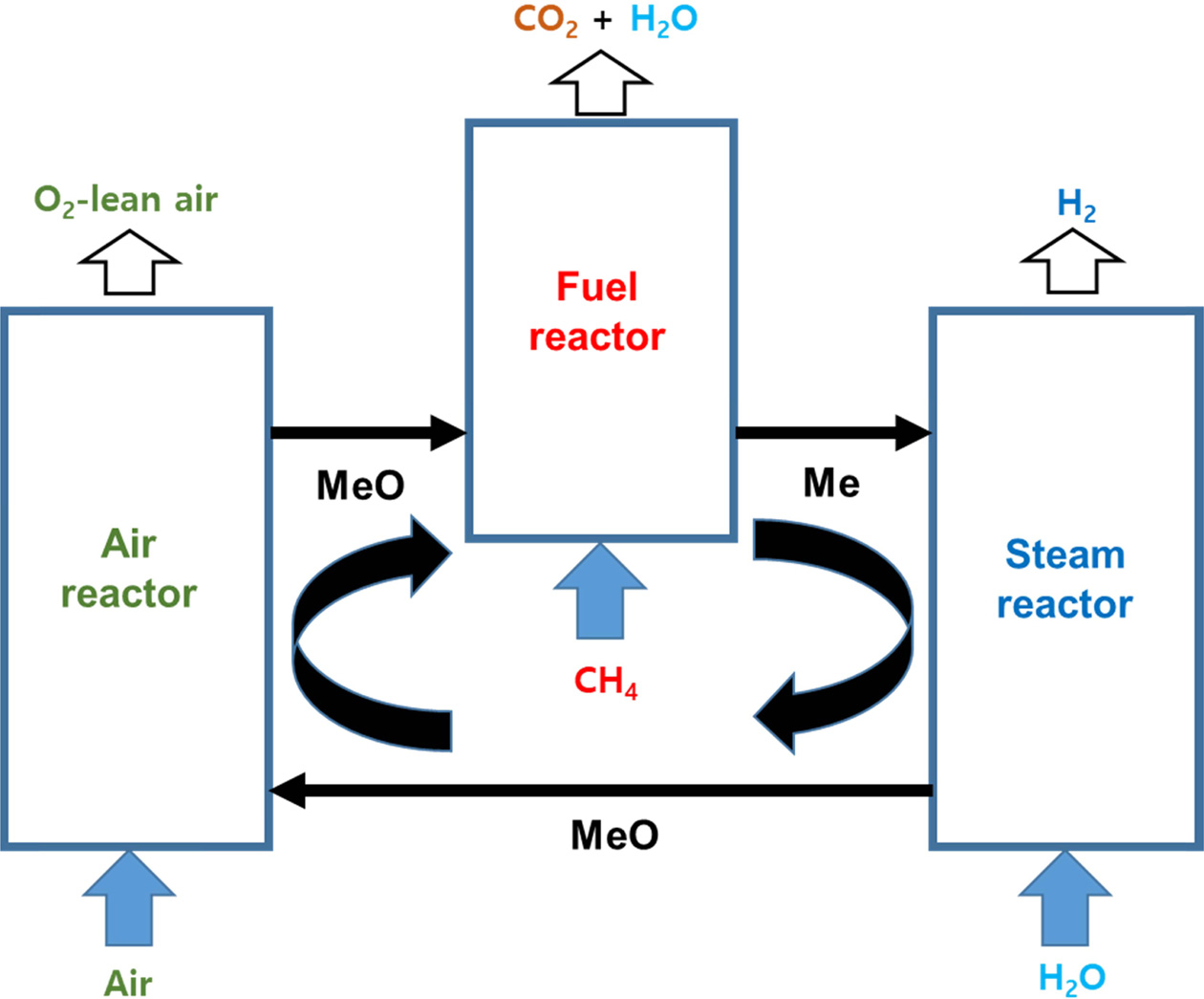
A CLHP system consists of an air reactor, fuel reactor,
and steam reactor, as shown in Fig. 1. In the air reactor, the metal (Me)
reacts with oxygen in the air to become metal oxide (MeO).
2Me (s) + O2 (g) → 2MeO (s) (exothermic
reaction)
(1)
In the fuel reactor, the fuel such as CH4
reacts with the metal oxide (MeO). The metal oxide is reduced to metal (Me) and
the fuel is burned to discharge carbon dioxide and water.
4MeO (s) + CH4 (g) → 4Me (s) + CO2
(g) + 2H2O (g)
(endothermic reaction) (2)
In the steam reactor, the metal (Me) reacts with water to
form metal oxide (MeO) and generate hydrogen.
Me (s) + H2O (g) → MeO (s) + H2 (g)
(exothermic reaction) (3)
In the above reactions, the metal oxide undergoing the
re-dox reaction is called an oxygen carrier material. The transition metal
oxide is usually used as an oxygen carrier material for CLHP. In the CLHP
process, the oxygen carrier material plays an important role not only
in transferring the oxygen required for combustion, but
also in splitting water to produce hydrogen. Therefore, it
is very important to develop high-performance oxygen carrier materials with
high oxygen transfer rates, high oxygen
transfer capacities, and excellent catalytic activity for water
splitting. Oxides of Cu, Ni, Mn, and Sn have been used as oxygen
carrier materials in CLHP. Among these metal oxides, Fe-based
oxygen carrier materials have the advantages of high oxygen transfer capacity,
low carbon deposition, lack of environmental harm, and low
cost [14-16]. However, a conventional Fe-based oxygen
carrier material such as Fe2O3 experiences
grain growth with re-dox cycling, leading to a decrease in
the surface area and consequent reduction of conversion efficiency
[17]. It has been reported that the NiFe2O4 spinel phase
at high temperatures exhibited higher oxygen transfer capacity and stability
than individual Fe2O3 [18, 19]. Although NiFe2O4
exhibits oxygen carrying stability with a high oxygen
transfer capacity during re-dox cycling, it still has slow re-dox reaction
kinetics compared to conventional oxygen carrier materials.
To improve the re-dox reaction kinetics of NiFe2O4,
in the present work we added gadolinium-doped ceria (GDC, Ce0.9Gd0.1O1.95)
as a promoter to improve the oxygen transfer rate. It is well known that GDC
has oxygen storage capability due to its formation of oxygen
vacancies, and GDC has thus been widely used as a catalyst [20, 21].
Therefore, the addition of GDC may enlarge the
reaction site. The present report describes our systematic investigation of the
effects of GDC as a promoter upon the oxygen transfer properties of NiFe2O4/GDC
composite oxygen carrier materials for CLHP.
|
Fig. 1 Schematic of CLHP system. |
NiFe2O4 powder was synthesized by a
solid-state reaction method. Stoichiometric amounts of NiO (Alfa Aesar,
UK) and Fe2O3 (Alfa Aesar, UK) were mixed by ball
milling in ethanol for 48 h, followed by calcination in air at
1,200 °C for 3 h. To make NiFe2O4/GDC composite
oxygen carrier materials, the calculated amount of commercial GDC (Ce0.9Gd0.1O1.95,
Kceracell Co. Ltd., Korea) powder was mixed with the
synthesized NiFe2O4 powder by a ball milling
process. NiFe2O4/GDC composite
powders with various amounts of GDC (0, 5 10, 15 wt %) were
prepared by ball milling with zirconia balls for 24 h in ethanol, and the
resulting mixtures were dried at 150 °C for 12 h.
Phase analysis was carried out by means of X-ray
diffraction analysis (XRD; MAX-2500, Rigaku, Japan) using a Cu Kα radiation
source. Diffraction patterns were recorded at the scan rate of 4°/min in the 2θ
range of 20° to 80°. The composition of the reduced sample was confirmed by
X-ray flourescence spectrometer (XRF; PW2404, Philips, USA). The valence state
of Fe in the sample was analyzed by X-ray photoelectron spectroscopy (XPS; AXIS
Ultra DLD Kratos, UK) with monochromatic Al Kα. The
morphological changes during the re-dox cycle were
monitored using a field emission scanning electron microscope (FE-SEM; SN-300,
Hitachi, Japan).
Temperature programed reduction (TPR) and temperature
programed oxidation (TPO) were carried out with gas
chromatography (GC; YL6100GC, Youngin, Korea) to
analyze the reduction and oxidation of NiFe2O4/GDC
composite oxygen carrier materials depending on the temperature. The
temperature was increased from room temperature to 900 °C at a heating
rate of 3 °C/min. 5% H2/Ar and 10% H2O/Ar were used
as the reducing and oxidizing gases, respectively. The re-dox
cycling tests were also carried out with GC. The temperature was raised to 900
°C at 10 °C/min in an Ar atmosphere and maintained for 12 h. When the
temperature reached 900 °C, 5% H2/Ar for reduction and
10% H2O/Ar for oxidation were alternately poured for 1
h. Ar was purged between each reduction and oxidation step for 1 h.
The oxygen transfer properties of the NiFe2O4/GDC
composite oxygen carrier materials based on the re-dox reaction were
evaluated by means of thermal gravimetric analysis
(TGA; TGA-N1000, Shinko, Korea) at 900 °C. 5% H2/Ar and air were
used as the reducing and oxidizing gases, respectively. Between each reduction
and oxidation step, the reactor was purged with Ar for 3 min to prevent mixing
of the reducing and oxidizing gases.
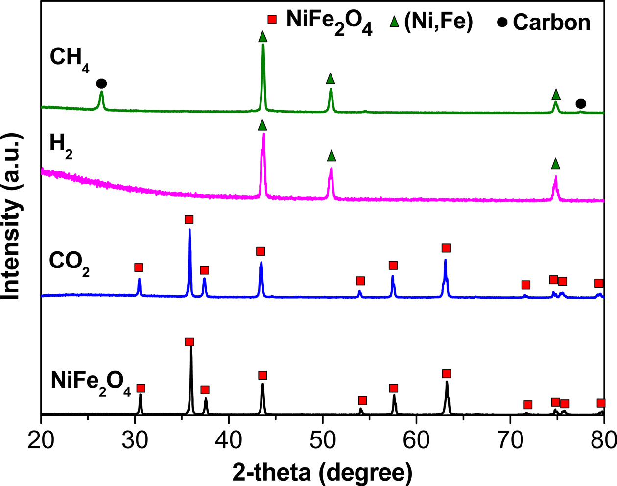
The XRD patterns of the NiFe2O4
samples synthesized and reacted with various gases are shown in Fig. 2.
NiFe2O4 powder synthesized at 1,200 °C for 3 h in
air was formed in a single phase of spinel without any detectable impurity, and
the diffraction peaks matched well with those of NiFe2O4
(JCPDS No. 00-010-0325). Since the product gases for CH4 are H2O
and CO2, as described in Eq. (2), oxygen carrier materials are
exposed to a CO2-rich atmosphere in the fuel reactor. As
shown in Fig. 2, no carbonate phases such as NiCO3
or FeCO3 were observed after the reaction with CO2.
Therefore, NiFe2O4 was not influenced by CO2
in the fuel reactor at 900 °C. Meanwhile, the NiFe2O4
powders reacted with H2 and CH4 at
900 °C for 1 h showed a single phase of (Ni,Fe) alloy. In the case of CH4,
carbon peaks due to a methane cracking reaction (CH4 → C + 2H2)
were detected.
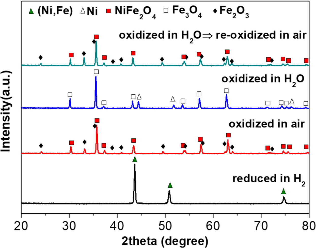
To confirm the re-dox mechanism of NiFe2O4,
phase analysis was carried out after reduction in H2 followed by
oxidation in air or H2O. The (Ni,Fe) alloy, which was the NiFe2O4
sample reduced in H2, did not return to NiFe2O4
after re-oxidation in air, as shown in Fig. 3. If the (Ni,Fe) alloy was a
stoichiometric compound such as NiFe2, the re-oxidized (Ni,Fe) alloy
sample must have been a single phase of NiFe2O4. However,
the sample re-oxidized in air showed two phases of NiFe2O4
and Fe2O3. Therefore, the (Ni,Fe) alloy was formed in the
Fe-rich composition such as NixFe2 (0 < x < 1).
This can be confirmed by the XRF data, as shown
in Table 1. It has also been reported that Ni can be volatilized in the
presence of H2O at high temperatures [22].
The reduction of NiFe2O4 took place
as a stepwise process, and the following pathway is suggested: NiFe2O4
→ Ni-Fe2O3 → Ni-Fe3O4 → Ni-FeO →
Ni-Fe [23]. Based on the composition and phase analysis, the reduction
mechanism of NiFe2O4 at 900 °C can be described as
follows.
NiFe2O4 (s) + H2 (g) →
xNi (s) + Fe2O3 (s)
+ H2O (g) + (1-x)Ni (g) (4)
Fe2O3 (s) + 1/3H2 (g) →
2/3Fe3O4 (s) + 1/3H2O (g)
(5)
2/3Fe3O4 (s) + 2/3H2 (g) →
2FeO (s) + 2/3H2O (g)
(6)
2FeO (s) + 2H2 (g) → 2Fe (s) + 2H2O
(g) (7)
Therefore, the overall reduction reaction in H2
is as follows.
NiFe2O4 (s) + 4H2
(g) → xNi (s) + 2Fe (s) + 4H2O (g)
+ (1-x)Ni (g) (8)
= NiFe2O4 (s) + 4H2 (g) →
NixFe2 (s) + 4H2O (g)
+ (1-x)Ni (g) (9)
When NixFe2 was oxidized in air, the
products were NiFe2O4 and Fe2O3 as
shown in Fig. 3. Therefore, the reduced NiFe2O4 (NixFe2)
reacted with oxygen in the air to induce the oxidation reaction as follows.
xNi (s) + x/2O2 (g) → xNiO (s) (10)
2Fe (s) + O2 (g) → 2FeO (s) (11)
2FeO (s) + 1/3O2 (g) → 2/3Fe3O4
(s) (12)
2/3Fe3O4 (s) + 1/6O2 (g) →
Fe2O3 (s) (13)
The overall oxidation reaction in air is as follows.
xNi (s) + 2Fe (s) + (3+x)/2O2 (g) → xNiO (s)
+ Fe2O3 (s) (14)
= NixFe2 (s) + (3+x)/2O2
(g) → xNiFe2O4 (s)
+ (1-x)Fe2O3 (s) (15)
Meanwhile, it has been reported that reduced nickel oxide
or metallic nickel are difficult to oxidize by steam due to thermodynamic
limitations [14,19,23,24]. Therefore, most of the reduced nickel ferrite can
only be oxidized to be a mixture of Fe3O4 and Ni under
steam. This result corresponds to the existence of Fe3O4
and Ni phases in our sample oxidized in H2O, as shown in Fig. 3. In
the steam reactor, NixFe2 reacted with H2O to
induce the oxidation reaction as follows.
xNi (s) → xNi (s) (16)
2Fe (s) + 2H2O (g) → 2FeO (s) + 2H2
(g) (17)
2FeO (s) + 2/3H2O (g) → 2/3Fe3O4
(s) + 2/3H2 (g)
(18)
The overall oxidation reaction in steam is as follows.
xNi (s) + 2Fe (s) + 8/3H2O (g) → xNi (s) +
2/3Fe3O4 (s)
+ 8/3H2 (g) (19)
= NixFe2 (s) + 8/3H2O (g)
→ xNi (s) + 2/3Fe3O4 (s)
+ 8/3H2 (g) (20)
When the oxygen carrier material oxidized in the steam
reactor flowed into the air reactor, un-reacted Ni and Fe3O4
became fully re-oxidized by oxygen as follows.
xNi (s) + x/2O2 (g) → xNiO (s) (21)
2/3Fe3O4 (s) + 1/6O2 (g) →
Fe2O3 (s) (22)
The overall re-oxidation reaction in air after the oxidation
in steam is as follows.
xNi (s) + 2/3Fe3O4 (s) + (1+3x)/6O2
(g) → xNiO (s)
+ Fe2O3 (s) (23)
= xNi (s) + 2/3Fe3O4 (s) + (1+3x)/6O2
(g) →
xNiFe2O4 (s) + (1-x)Fe2O3
(s) (24)
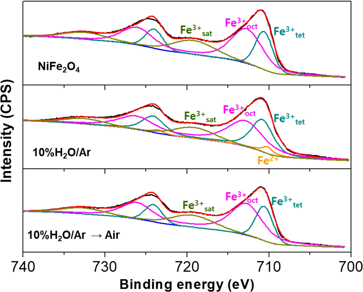
XPS analysis was also performed in order to verify the
valence state of Fe in NiFe2O4 before and after the
oxidation reaction at 900 °C for 1 h. The XPS spectra obtained for the
various atmospheres are shown in Fig. 4. The binding energies of Fe 2p3/2, Fe 2p3/2
satellite, and
Fe 2p1/2 in Fe2O3 are 711.0, 718.8, and 724.6 eV,
respectively [25]. The peak positions of Fe 2p3/2, Fe 2p3/2 satellite, and Fe
2p1/2 in NiFe2O4 in this study were observed at 711.0,
719.1, and 724.3 eV, respectively, which indicates that the valence state of Fe in NiFe2O4 is 3+.
Moreover, Dey et al. reported that the deconvolution
of the Fe 2p peak of the NiFe2O4 into two components
correspond to the octahedral 2p3/2 and 2p1/2 peaks, and the tetrahedral 2p3/2
and 2p1/2 peaks [26]. The results are consistent with this study and indicate
the absence of Fe2+ component and confirmation of the oxygen
stoichiometric compound. Alternatively, in the case of the sample oxidized in
10% H2O/Ar, the peaks of Fe2+ (Fe 2p3/2) and Fe2+
(Fe 2p1/2) were identified at 710.2
and 723.7 eV, respectively. These
results correspond to the peak positions of Fe3O4 [25],
indicating that the valence state of Fe in the sample oxidized in 10% H2O/Ar
is a mix of 2+ and 3+. Interestingly, the peak positions of Fe 2p3/2, Fe 2p3/2
satellite, and Fe 2p1/2 in the sample re-oxidized in air are identical to those
of Fe2O3 and NiFe2O4.
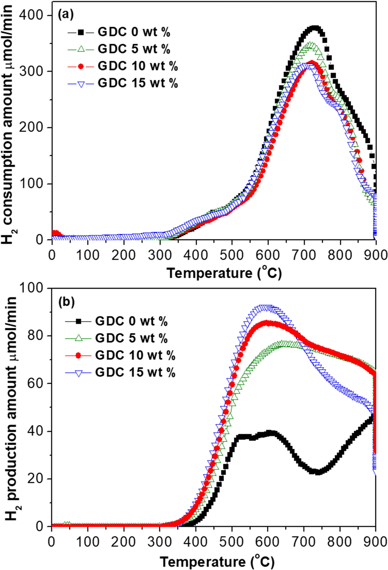
The reduction and oxidation properties of NiFe2O4/GDC
composite oxygen carrier materials were determined by H2-TPR
and H2O-TPO, as shown in Fig. 5. It has been reported that Fe2O3
exhibits a three-step reduction mechanism, with one reduction peak at
a lower temperature (360-415 °C) corresponding to the reduction of Fe2O3
→ Fe3O4, and two broad reduction peaks at 500-750 °C and
800-900 °C corresponding to reduction steps of Fe3O4
→ FeO and FeO → metallic Fe, respectively [27-29]. It has been also reported
that the H2-TPR pattern of bulk NiO consists of one broad peak in
the range of 327 to 677 °C with a maximum peak at 409 °C. The results in the present
study (Fig. 5a) were in good agreement with the previous works, which indicates that the established reduction mechanism
is plausible. In particular, the peak corresponding to the reduction steps of
Fe3O4 → FeO shifted to the low-temperature region with
increasing GDC content. Based on the H2-TPR data, it can be
concluded that the reduction reactivity of the NiFe2O4/GDC
composite slightly increased with increasing the amount of GDC. Similarly,
based on the H2O-TPO data (Fig. 5b), it is expected that the amount
of oxidation reaction as well as the oxidation reactivity of NiFe2O4/GDC
composite will increase with increasing the GDC content.
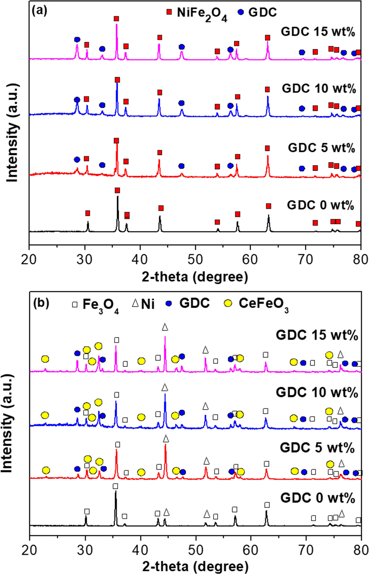
The XRD patterns of NiFe2O4/GDC
composites before and after H2-TPR and H2O-TPO tests are
shown in Fig. 6. All the XRD peaks of the samples before H2-TPR and
H2O-TPO tests (Fig. 6a) were matched with those of NiFe2O4
or GDC, with no traces of secondary peaks. On the contrary, since the reduced
NiFe2O4 (NixFe2) in the NiFe2O4/GDC
composites during the H2-TPR test was oxidized to be a mixture of Ni
and Fe3O4 under steam during the H2O-TPO test,
both Ni and Fe3O4 peaks were detected after H2-TPR
and H2O-TPO tests (Fig. 6b). Interestingly, CeFeO3
was observed in the samples containing GDC. Mahmoodi et al. [30] also
reported the formation of CeFeO3 in the Fe2O3-CeO2
oxygen carrier system during the re-dox cycle.
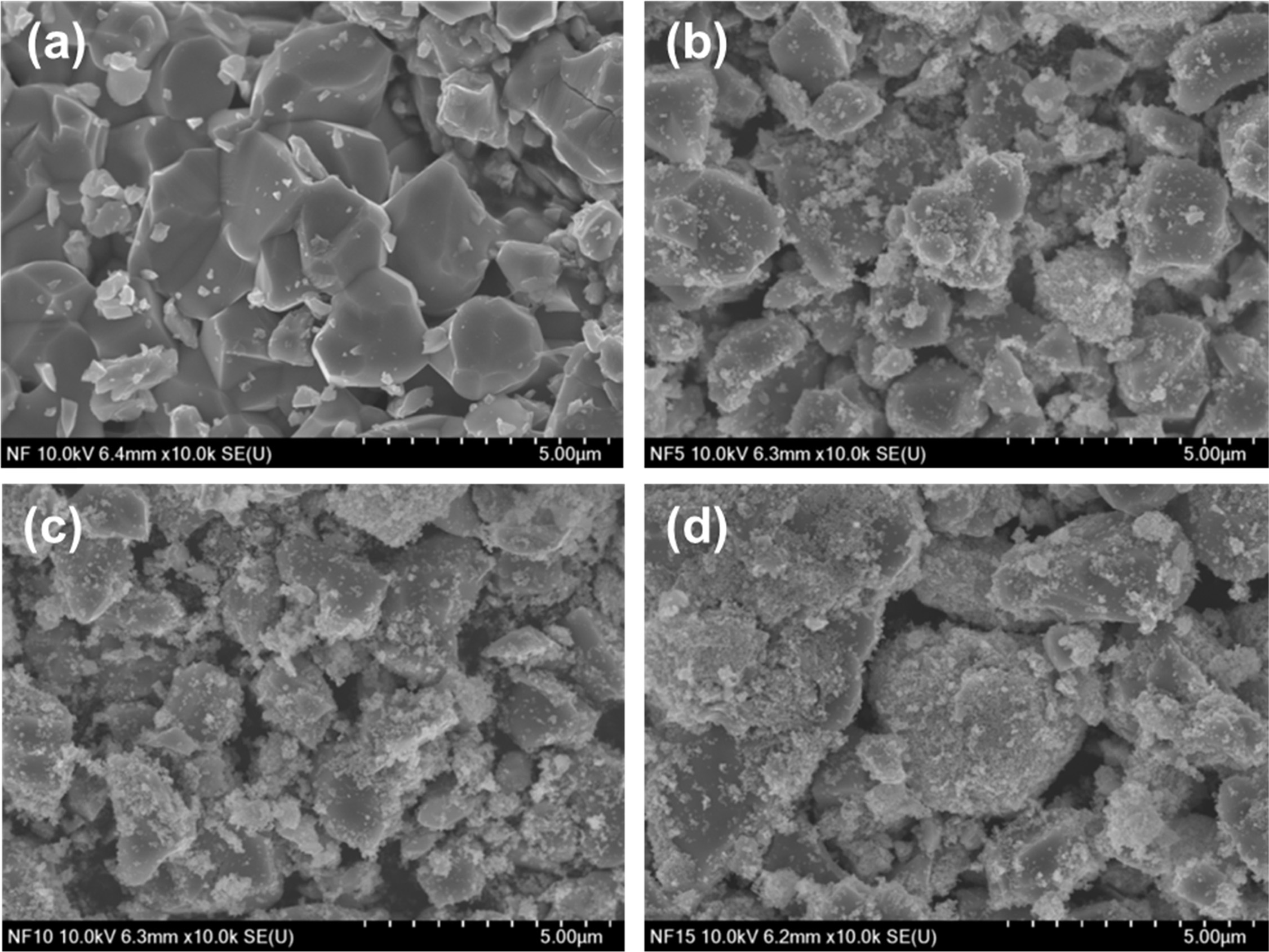
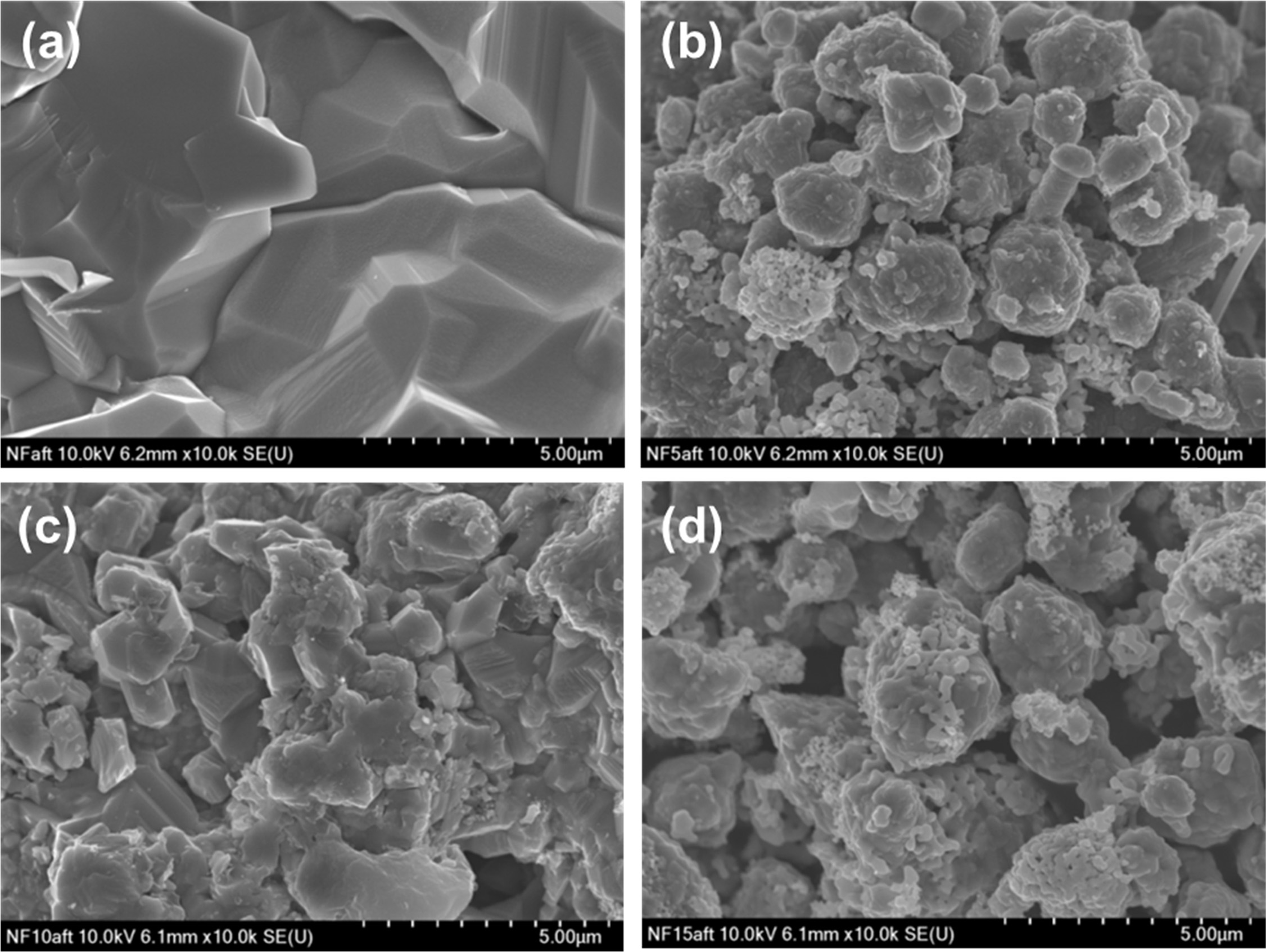
The microstructures of NiFe2O4/GDC
composites before and after H2-TPR and H2O-TPO tests are
shown in Figs. 7 and 8. All the samples had a porous structure before H2-TPR
and H2O-TPO tests (Fig. 7a-d), and the fine GDC particles were
evenly distributed over the NiFe2O4 particles (Fig.
7b-d). Notably, the NiFe2O4 sample without GDC exhibited
severe agglomeration after the H2-TPR and H2O-TPO tests
(Fig. 8a), while the well-dispersed GDC particles in the NiFe2O4/GDC
composites (Fig. 8b-d) suppressed the aggregation of NiFe2O4
particles and maintained the porous structure.
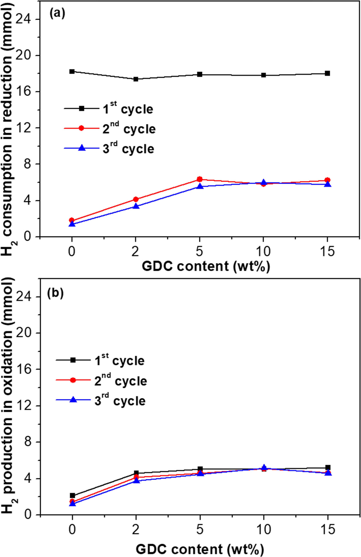
Fig. 9 shows the amount of H2 consumption and
production at 900 °C in the fuel reactor with 5% H2/Ar and
in the steam reactor with 10% H2O/Ar, respectively.
After the first cycle, the amount of H2 consumption decreased
significantly (Fig. 9a). This indicates that the reduced NiFe2O4
(NixFe2) could not be fully oxidized to NiFe2O4
by H2O. This may be ascribed to the deactivation problem caused by
the agglomeration of Ni. The oxidation-reduction reaction was limited to only a
part of the agglomerated Ni surface after the first cycle. The amount of H2
production in each cycle (Fig. 9b) was similar to that of H2
consumption in the second and third cycles (Fig. 9a), while the amount of H2
consumption and production of the NiFe2O4/GDC composites
in the fuel and the steam reactor, respectively, increased
with increasing GDC content. This might have been due to the suppression of
agglomeration by the well-dispersed GDC particles, as shown in Fig. 8.
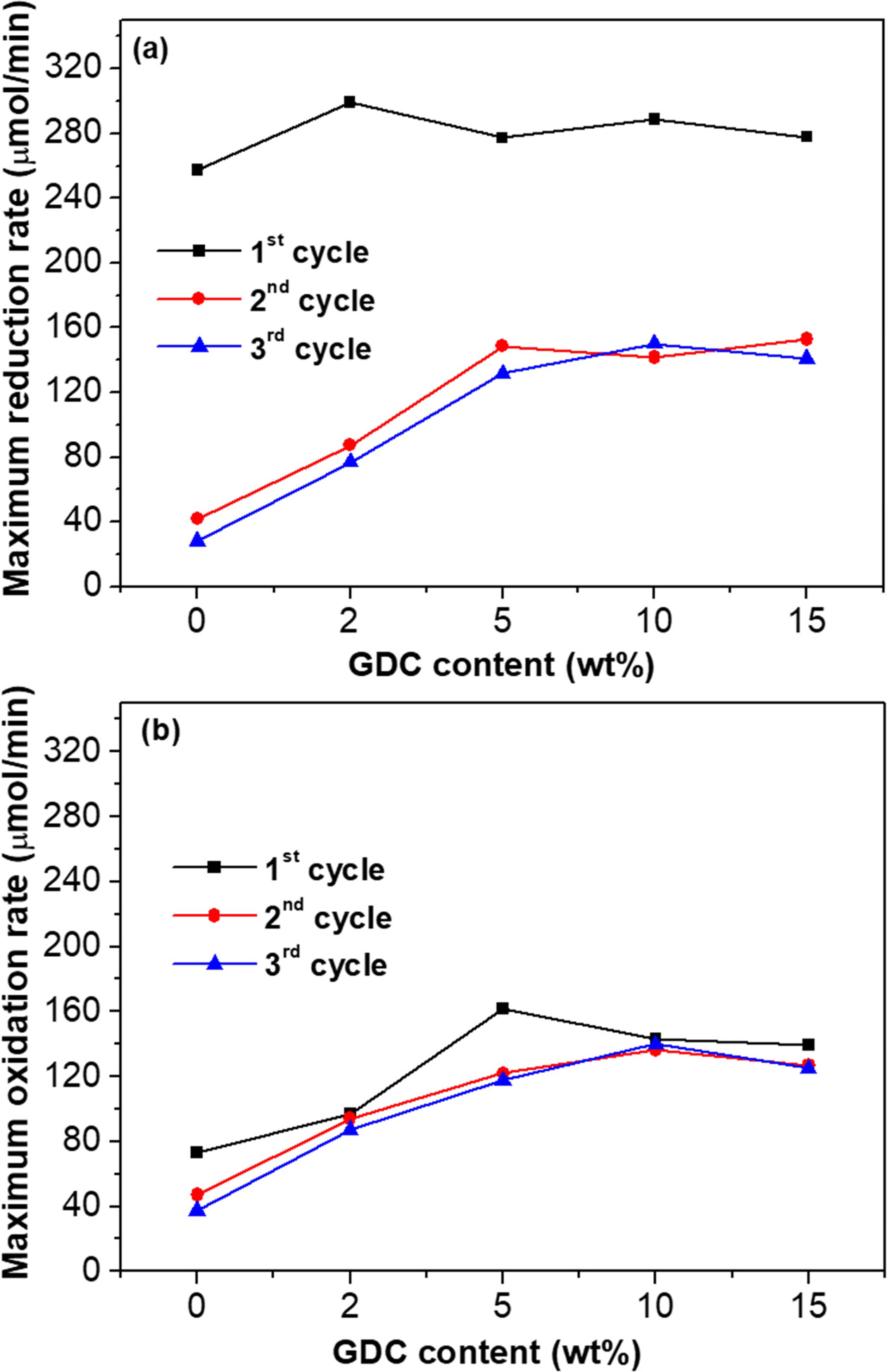
The maximum reaction rates of the NiFe2O4/GDC
composites, as shown in Fig. 10, were also similar to the amount of H2
consumption (Fig. 9a) and production (Fig. 9b) for the re-dox reaction. Because
the re-dox reaction rate increased in proportion to the number of active sites
where H2 or H2O could react, the maximum reaction rates
for the reduction (Fig. 10a) and oxidation (Fig. 10b) increased with increasing
GDC content.
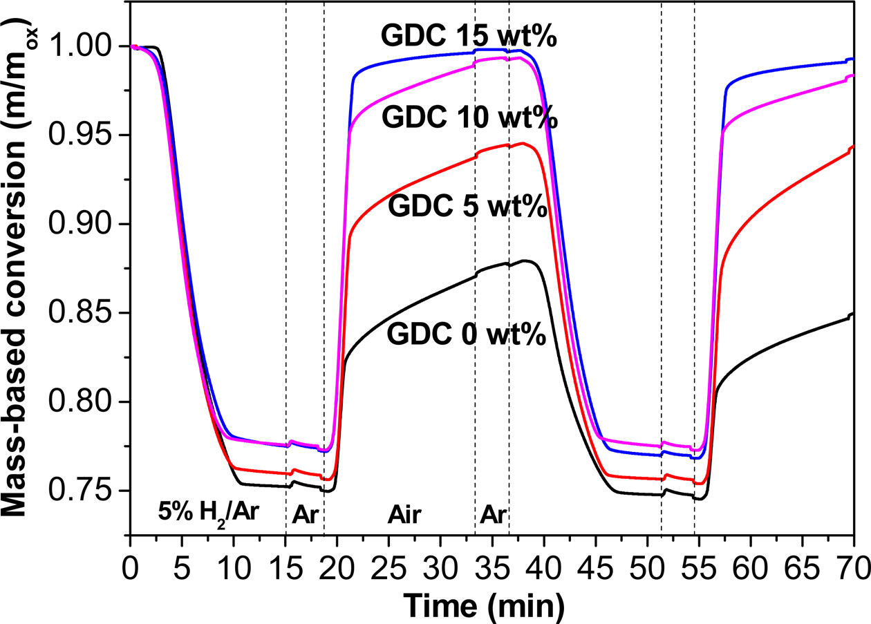
We used TGA to evaluate the oxygen transfer properties
of the NiFe2O4/GDC composite oxygen carrier materials
based on the re-dox reaction between the fuel and air reactors. Re-dox curves
of the NiFe2O4/GDC composites at 900 °C with 5% H2/Ar
and air used as the reducing and oxidizing gases, respectively, are shown in
Fig. 11. The empirical oxygen transfer capacity of NiFe2O4
was 24.7 wt% at the first cycle, which was similar to the theoretical value of
27.3 wt% based on Eq. (9). However, in the case of NiFe2O4
without GDC, the weight gain observed during oxidation was
much smaller than the weight loss during reduction, indicating
that the re-dox reaction was irreversible. This indicates that the oxygen
transfer capacity of pure NiFe2O4 degraded significantly
during the re-dox cycle. In contrast, the NiFe2O4/15wt%
GDC composite showed a full recovery of weight during oxidation.
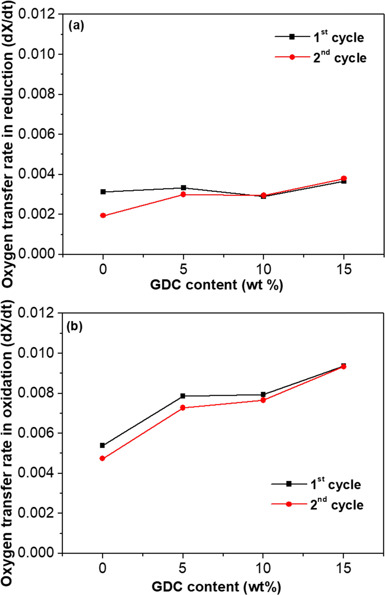
The oxygen transfer rate (dX/dt), referring to the change
in the conversion rate per unit time, can be calculated from TGA data (Fig.
11). Fig. 12 shows the oxygen transfer rate of the NiFe2O4/GDC
composite for reduction and oxidation reactions, respectively. The oxygen
transfer rates for the reduction (Fig. 12a) and oxidation (Fig. 12b) reactions
increased with increasing the GDC content. This suggests that GDC may affect
the reaction kinetics of NiFe2O4/GDC composites.
Interestingly, the oxygen transfer rate for the oxidation reaction increased
significantly for the composite that included 15 wt% GDC, as shown in Fig.
12(b).
It has been reported that GDC has oxygen storage
capability due to its oxygen vacancies [31,32]. It is also well known that the
surface adsorption of the reaction gas improves with the amount of oxygen
vacancies on the surface. Therefore, the well-dispersed fine GDC particles on
the surface of NiFe2O4 can accelerate the surface adsorption
of reaction gases due to the oxygen vacancies formed on the
surface of the GDC. Moreover, fine GDC particles may
suppress the grain growth of NiFe2O4. As a result, the
specific surface area per unit volume of the NiFe2O4/GDC
composite was larger than that of the pure NiFe2O4.
This also increases the reaction rate in terms of the enlargement of
active sites.
The primary advantage of the addition of GDC was that no
significant agglomeration was observed before or after the re-dox cycle.
Therefore, one can expect that an NiFe2O4/GDC composite may exhibit
oxygen carrying stability during long-term
cycles, based on the result of the
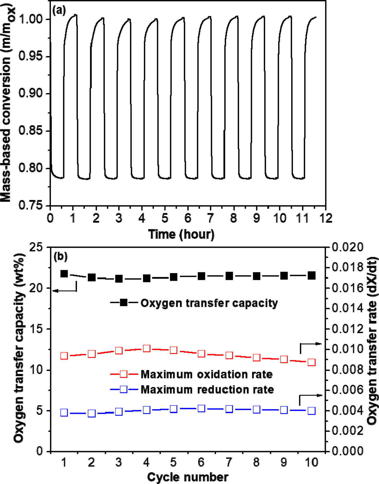
reversible re-dox reaction and microstructural observation. Fig. 13(a) shows re-dox curve of the NiFe2O4/15wt%
GDC composite at 900 °C during the 10 re-dox cycles, measured by TGA.
Based on the re-dox curve, the calculated oxygen transfer capacity retention
and the variation of oxygen transfer rate are shown in Fig. 13(b). In fact, in this study the NiFe2O4/15 wt%
GDC composite showed no significant degradation in the oxygen transfer capacity and reaction rate after the tenth re-dox
cycle, as shown in Fig. 13.
|
Fig. 2 XRD patterns of NiFe2O4 obtained for the various reaction gases at 900 °C for 1 h. |
|
Fig. 3 XRD patterns of NiFe2O4 according to re-dox reaction at 900 °C for 1 h. |
|
Fig. 4 XPS spectra of NiFe2O4 before and after the oxidation reaction at 900 °C for 1 h. |
|
Fig. 5 (a) TPR data, and (b) TPO data of NiFe2O4/GDC composites obtained for 5% H2/Ar and 10% H2O/Ar as the reducing and oxidizing gases, respectively. |
|
Fig. 6 XRD patterns of NiFe2O4/GDC composites (a) before and (b) after H2-TPR and H2O-TPO tests. |
|
Fig. 7 FE-SEM images of NiFe2O4/GDC composites before H2-TPR and H2O-TPO tests: (a) 0 wt% GDC, (b) 5 wt% GDC, (c) 10 wt% GDC, and (d) 15 wt% GDC. |
|
Fig. 8 FE-SEM images of NiFe2O4/GDC composites after H2-TPR and H2O-TPO tests: (a) 0 wt% GDC, (b) 5 wt% GDC, (c) 10 wt% GDC, and (d) 15 wt% GDC. |
|
Fig. 9 (a) H2 consumption, and (b) production of NiFe2O4/GDC composites versus GDC in reduction reaction with 5% H2/Ar and in oxidation reaction with 10% H2O/Ar, respectively, measured by GC. |
|
Fig. 10 Maximum reaction rate of NiFe2O4/GDC composites versus GDC content for (a) the reduction with 5% H2/Ar and (b) the oxidation with 10% H2O/Ar, measured by GC. |
|
Fig. 11 Re-dox curves of the NiFe2O4/GDC composites at 900 °C with 5% H2/Ar and air used as the reducing and oxidizing gases, respectively, measured by TGA. |
|
Fig. 12 Maximum oxygen transfer rate of NiFe2O4/GDC composites versus GDC content for (a) the reduction reaction with 5% H2/Ar and (b) the oxidation reaction with air, measured by TGA. |
|
Fig. 13 (a) Re-dox curve, and (b) oxygen transfer capacity retention and rate stability of the NiFe2O4/15wt% GDC composite at 900 °C during the 10 re-dox cycles, measured by TGA. |

This study characterizes NiFe2O4/GDC
composites as oxygen carrier materials for CLHP. The re-dox mechanisms represented
in the solid state in the fuel, in steam, and in the air reactor were NiFe2O4→NixFe2,
NixFe2→Ni+Fe3O4, and Ni+Fe3O4→NiFe2O4+Fe2O3,
respectively. Carbon dioxide could be captured from the fuel reactor and
hydrogen could be produced from the steam reactor.
Both the amount and rate of hydrogen production for the
NiFe2O4/GDC composites increased as the GDC content
increased. Moreover, the oxygen transfer rate for both the reduction and
oxidation reactions increased significantly with increasing GDC
content. The positive effect of the addition of GDC may be
mainly ascribed to an increase in the surface adsorption of reaction gases via
the oxygen vacancies formed on the surface of the GDC, as well as the
enlargement of the active sites due to suppression of the agglomeration of NiFe2O4
by the well-dispersed fine GDC particles on the surface of NiFe2O4.
In the case of the NiFe2O4/15wt% GDC
composite, no significant degradation in the oxygen transfer capacity or
reaction rate during the re-dox cycles was observed. Assuming that the reaction
rate of hydrogen production per hour is maintained, the amount of hydrogen
production for the NiFe2O4/15wt% GDC composite would be
2,702 L/day per unit mass (kg). In this regard, an NiFe2O4/GDC
composite can be a promising oxygen carrier material for CLHP due to its high
performance and stability. However, since the cost of the GDC is
still high, trade-offs in terms of performance improvement
and cost as well as industrial scalability should be considered. Therefore, it
is necessary to develop a technology that can maximize performance while
minimizing the content of GDC such as use of nano-composite powder.
This research was supported by Basic Science Research
Program through the National Research Foundation of Korea (NRF) funded by the
Ministry of Education (2017R1D1A1B03031541). This work was also
supported by the Technology Development Program to Solve
Climate Changes of the National Research Foundation
(NRF) grant funded by the Korea government (Ministry of
Science and ICT) (2017M1A2A2044930).
- 1. K.S. Go, S.R. Son, S.D. Kim, K.S. Kang, and C.S. Park, Int. J. Hydrogen Energy 34[3] (2009) 1301-1309.
-

- 2. R.D. Solunke and G. Veser, Ind. Eng. Chem. Res. 49[21] (2010) 11037-11044.
-
- 3. S. Dunn, Int. J. Hydrogen Energy 27[3] (2002) 235-264.
-
- 4. M. Momirlan and T.N. Veziroglu, Renew. Sust. Energ. Rev. 6[1-2] (2002) 141-179.
-
- 5. IPCC, in 2014: Climate Change 2014: Synthesis Report, 2015, edited by Pachauri, R. K., Allen, M. R., Barros, V. R., Broome, J., Cramer, W., Christ, R., Church, J. A., Clarke, L., Dahe, Q., Dasgupta, P., Dubash, N. K., Edenhofer, O., Elgizouli, I., Field, C. B., Forster, P., Friedlingstein, P., Fuglestvedt, J., Gomez-Echeverri, L., Hallegatte, S., Hegerl, G., Howden, M., Jiang, K., Jimenez Cisneroz, B., Kattsov, V., Lee, H., Mach, K. J., Marotzke, J., Mastrandrea, M. D., Meyer, L., Minx, J., Mulugetta, Y., O'Brien, K., Oppenheimer, M., Pereira, J. J., Pichs-Madruga, R., Plattner, G.-K., Pörtner, Hans-Otto , Power, S. B., Preston, B., Ravindranath, N. H., Reisinger, A., Riahi, K., Rusticucci, M., Scholes, R., Seyboth, K., Sokona, Y., Stavins, R., Stocker, T. F., Tschakert, P., van Vuuren, D. and van Ypserle, J.-P., Intergovernmental Panel on Climate Change Press (2015) p.151.
-
- 6. S.A. Rackley, in “Carbon Capture and Storage 2nd Edition” (Butterworth-Heinemann Press, 2017) p.22.
- 7. D.Y.C. Leung, G. Caramanna, and M.M. Maroto-Valer, Renew. Sust. Energ. Rev. 39 (2014) 426-443.
-
- 8. J. Gibbins and H. Chalmers, Energy Policy 36[12] (2008) 4317-4322.
-
- 9. V.J. Aston, B.W. Evanko, and A.W. Weimer, Int. J. Hydrogen Energy 38[22] (2013) 9085-9096.
-
- 10. P. Gupta, L.G. Velazquez-Vargas, and L.S. Fan, Energy Fuels 21[5] (2007) 2900-2908.
-
- 11. L.F. de Diego, M. Ortiz, F. García-Labiano, J. Adánez, A. Abad, and P. Gayán, J. Power Sources 192[1] (2009) 27-34.
-
- 12. M. Luo, Y. Yi, S. Wang, Z. Wang, M. Du, J. Pan, and Q. Wang, Renew. Sust. Energ. Rev. 81 (2018) 3186-3214.
-
- 13. L. Protasova and F. Snijkers, Fuel 181 (2016) 75-93.
-
- 14. F. Li, H.R. Kim, D. Sridhar, F. Wang, L. Zeng, J. Chen, and L.-S. Fan, Energy Fuels 23[8] (2009) 4182-4189.
-
- 15. Z. Huang, F. He, Y. Feng, K. Zhao, A. Zheng, S. Chang, G. Wei, Z. Zhao, and H. Li, Energy Fuels 28[1] (2014) 183-191.
-
- 16. M. Rydén and M. Arjmand, Int. J. Hydrogen Energy 37[6] (2012) 4843-4854.
-
- 17. J.R. Scheffe, M.D. Allendorf, E.N. Coker, B.W. Jacobs, A.H. McDaniel, and A.W. Weimer, Chem. Mater. 23[8] (2011) 2030-2038.
-
- 18. S. Yang, K. Kim, J.I. Baek, J.W. Kim, J.B. Lee, C.K. Ryu, and G. Lee, Energy Fuels 26[7] (2012) 4617-4622.
-
- 19. Y.L. Kuo, W.M. Hsu, P.C. Chiu, Y.H. Tseng, and Y. Ku, Ceram. Int. 39[5] (2013) 5459-5465.
-
- 20. Y.M. Choi, H. Abernathy, H.-T. Chen, M.C. Lin, and M. Liu, Chem. Phys. Chem. 7 (2006) 1957-1963.
-
- 21. C. Sun, H. Li, and L. Chen, Energy Environ. Sci. 5 (2012) 8475-8505.
-
- 22. G. Chen, G. Guan, Y. Kasai, and A. Abudula, Int. J. Hydro. Energy 37 (2012) 477-483.
-
- 23. S. Liu, F. He, Z. Huang, A. Zheng, Y. Feng, Y. Shen, H. Li, H. Wu, and P. Glarborg, Energy Fuels 30 (2016) 4251-4262.
-
- 24. K. Svoboda, A. Siewiorek, D. Baxter, J. Rogut, M. Puncochar, Chem. Pap. 61(2) (2007) 110-120.
-
- 25. T. Yamashita and P. Hayes, Appl. Surf. Sci. 254 (2008) 2441-2449.
-
- 26. J.K. Dey, A. Chatterjee, S. Majumdar, A.-C. Dippel, O. Gutowski, M.V. Zimmermann, and S. Giri, Phys. Rev. B 99 (2019) 144412.
-
- 27. T.S.T. Saharuddin, F. Salleh, A. Samsuri, R. Othaman, and M.A. Yarmo, Int. J. Chem. Eng. Appl. 6 (2015) 405-409.
-
- 28. G. Neri, A.M. Visco, S. Galvagno, A. Donato, and M. Panzalorto, Thermochim. Acta 329 (1999) 39-46.
-
- 29. X. Zhu, H. Wang, Y. Wei, K. Li, and X. Cheng, J. Rare Earths 28 (2010) 907-913.
-
- 30. F. Mahmoodi, S.H. Najibi, and A. Shariati, J. Am. Sci. 8[11] (2012) 453-459.
-
- 31. Y.M. Choi, H. Abernathy, H.-T. Chen, M.C. Lin, and M. Liu, Chem. Phys. Chem. 7 (2006) 1957-1963.
-
- 32. Z. Gu, K. Li, S. Qing, X. Zhu, Y. Wei, Y. Li, and H. Wang, RSC Adv. 4 (2014) 47191-47199.
-
 This Article
-
2020; 21(2): 148-156
Published on Apr 30, 2020
- 10.36410/jcpr.2020.21.2.148
- Received on Jul 19, 2019
- Revised on Feb 18, 2020
- Accepted on Feb 24, 2020
Services
- Abstract
introduction
experimental procedure
results and discussion
conclusions
- Acknowledgements
- References
- Full Text PDF
Shared
Correspondence to
- Ki-Tae Lee
-
bDivision of Advanced Materials Engineering, Jeonbuk National University, Jeonbuk, 54896 Republic of Korea
cHydrogen and Fuel Cell Research Center, Jeonbuk National University, Jeonbuk, 54896 Republic of Korea
Tel : +82-63-270-2290 Fax: +82-63-270-2386 - E-mail: ktlee71@jbnu.ac.kr
Clean-Energy Research Institute(CRI), Hanyang University, 222, Wangsimni-ro, Seongdong-gu, Seoul, 04763, Korea
E-mail: jcpr@hanyang.ac.kr