


- Multi objective optimization of wear characteristics on Al 7075/Al2O3/B4C composites - Desirability approach
Pridhar. Ta,*, Ravikumar. Kb, Sureshbabu. Ba, Srinivasan. Ra and Sathishkumar. Ba
aDepartment of Mechanical Engineering, Sri Krishna College of Technology, Coimbatore, India
bDepartment of Mechanical Engineering, Dr.NGP Institute of Technology, Coimbatore, India
Aluminium hybrid metal matrix
composites comprises of Al alloy embedded with multiple hard particulates to
improve the wear characteristics. In this study Al 7075/Al2O3/B4C
hybrid composite was fabricated with 5 wt.% B4C particles addition
and 2, 4, 6, 8 and 10 wt.% of Al2O3 by liquid metallurgy
route. The dry sliding wear behaviour of hybrid composites was investigated
under various sliding parameters using a pin on disc tribometer. Numerical
models were developed to predict the frictional and wear characteristics of the
composites. Analysis of variance method and confirmation experiments were
employed to validate the adequacy of the developed model. The composites with
high particle content exhibits better wear resistance at various sliding
conditions. Detailed metallurgical investigations were carried out on the on
worn surface. The wear rate was severe at higher loads due to the crater formation
and in addition to abrasive wear. The wear rate and coefficient of friction
were optimized using desirability based multi criteria optimization technique.
Keywords: Alumina, Boron carbide, SEM, XRD, EDS, Dry sliding wear, RSM, Optimization
Composite materials have become a need in the modern
decade to obtain numerous properties which were not achieved by monolithic
materials. It caters the increasing demand for enhanced mechanical and
tribological properties in aerospace, marine, defence and automotive
applications [1-3, 40]. The commonly used techniques in fabrication of hybrid
metal matrix composites (HMMC) are stir casting and powder metallurgy
technique. Stir casting route has remained as the most explored technique for
fabrication of hybrid composites due to its flexibility, simplicity and
commercial viability [4, 5, 38, 39]. Baradeswaran et al. [6] observed that the
addition of aluminium oxide to base alloy improved the tensile strength,
hardness, flexural strength and compression strength. Also the inclusion of
graphite improved the wear characteristics of the hybrid composites.
Investigations of Veeresh Kumar et al. [7] on addition of silicon carbide and aluminium
oxide to aluminium alloy indicate improvement in density,
tensile, micro hardness and wear of the base alloy. Ravikumar et al. [8]
observed that the wear in Aluminium/flyash composites,
decreased with increased fly ash particle size primarily due
to the interfacial strength between the base metal and its reinforcement. Dora
Siva Prasad et al. [9] in the studies of tribological behavior on
A356/SiC/Rice Hush Ash (RHA) composites observed
that increase in wear resistance was owing to the strengthening mechanism of
the matrix due to the thermal mismatch between the reinforcements and the base
alloy. Ravinder Kumar et al. [10] made an investigation on Al 7075/SiC/graphite
and concluded that load was the most noteworthy factor that affects the wear
rate. On observation of the wear SEM image of
Al/SiC/mica composites Rajmohan et al. [11] reported that
numerous long grooves and craters were found on worn
surfaces at higher load and the mechanism changed from
abrasive wear to delamination at higher load. Uthayakumar et al. [12] observed
high melt wear at high sliding speed and higher load because of the higher
order existence of local stress. Krishnan et al. [13] revealed that abrasive
wear prevails in particle reinforced composites, whereas adhesive wear was dominant
in base alloy. Radhika et al. [14] found a MML layer in the
surface which formed due to the increase in velocity on the counter
face of the specimen. An attempt has been made by Ravikumar et al. [15]
to predict the wear rate and coefficient of friction of Al356/fly
ash composites using Artificial Neural Network (ANN). Ravinder
Kumar et al. [10] made a comparison between Response
Surface Methodology (RSM) and ANN for the prediction of Surface
roughness measurement on Al 7075 hybrid composites and concluded that prediction
of RSM is good as compared to ANN. S. Selvi et al. [16] developed a
mathematical model for calculation of wear rate using response surface
methodology. Suresh et al. [17] applied RSM Box Behnken design method effectively
to reduce the number of trials and to develop a mathematical model
with high confidence level and employed ANOVA to verify the adequacy of the mathematical model. Vembu et al. [18]
developed a second order polynomial equation for the prediction of tensile
strength using RSM. Ravikumar et al. [19]
employed a multi response optimization technique based on desirability approach
to reveal the optimal process parameters of WEDM on Aluminium hybrid
composites. Ravikumar et al. [20] applied desirability based multi response
optimization to optimize the wear rate and coefficient of friction in abrasive
wear test.
From the above literature survey it is evident that many
researchers have put tremendous efforts to manufacture light weight and
efficient material for the automobile, marine and aerospace industries. However
limited works were carried out on Al 7075 hybrid composites.
Al 7075 aluminium alloy is being used to manufacture rock
climbing equipment, automotive components, hang glider
airframes, M16 rifles and aerospace applications due to their high strength to
weight ratio and good mechanical properties. The present investigation is to
manufacture Al 7075 hybrid composite by reinforcing the Al2O3
and B4C particulates and to study the dry sliding wear
of the hybrid composites. Scanning electron micrographs
(SEM) were used to study the influence of parameters on wear mechanisms. A
mathematical model was developed to predict the wear rate and coefficient
friction using RSM. The model adequacy was tested using ANOVA. Desirability
based Multi response optimization technique was instituted to
predict the optimized parameters. The
significance of this study is to develop a low weight superior
strength material in an affordable cost. This novel material may replace current
used alloys with superior quality. The Desirability optimization
technique which is used in this research is user friendly and has more accuracy
compared to other optimization techniques.
Materials
The composite comprises of Al 7075 as base material,
alumina and boron carbide as reinforcement. The chemical composition of the
matrix metal (Al 7075) used for the current study is shown Table 1. Al2O3
and B4C particulates are used to manufacture the composite with an
average particle size of 40 microns.
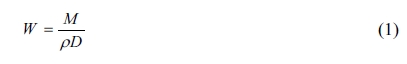
The casting was prepared using stir casting machine shown
in Fig. 1, Al 7075 reinforced with 2, 4, 6, 8 and 10 wt.%
alumina with constant 5 wt.% of boron carbide were
prepared by a stir casting technique. A weighed amount of Al 7075 alloy was
superheated to 750 °C in a conical shaped graphite crucible by
using an electrical resistance furnace. The melt was degassed using solid dry
hexachloroethane (C2 Cl6). The particulates
were preheated at 700 °C for 20 min. to remove the moisture content and the
reinforcements were added to the vortex at a constant feed rate. The composite
slurry was stirred continuously at a speed of 530 rpm for 15 minutes. 2 wt% of
magnesium was also included to enhance the wettability of the composites.
For proper mixing of the reinforcements with the matrix
alloy, stirring was continued for about 10 min even after the completion of
particulate additions. For comparative study, unreinforced aluminium alloy was
also prepared under similar cast conditions.
Micro
Structural Examinations
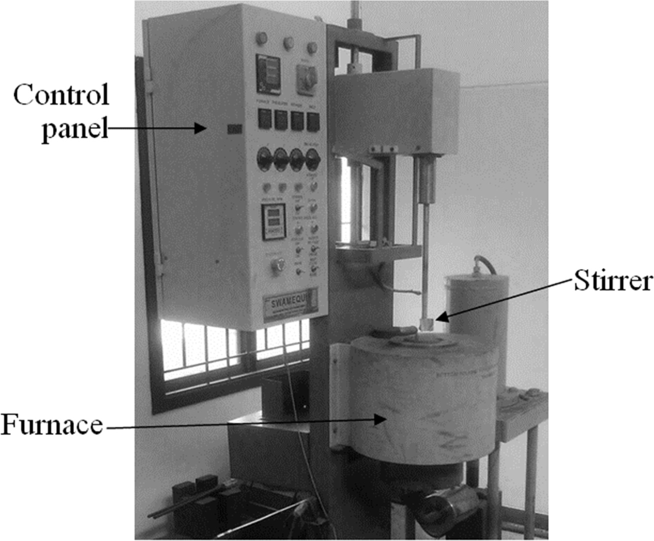
The microstructure of Al 7075/Al2O3/B4C
composites was examined using a scanning electron microscope
(JSM-6360). The cast samples for microstructure in- vestigation
were polished metallographically. The Polished specimen
was then etched with 10% of sodium hydroxide solution and
examined for uniformity in distribution of particulates
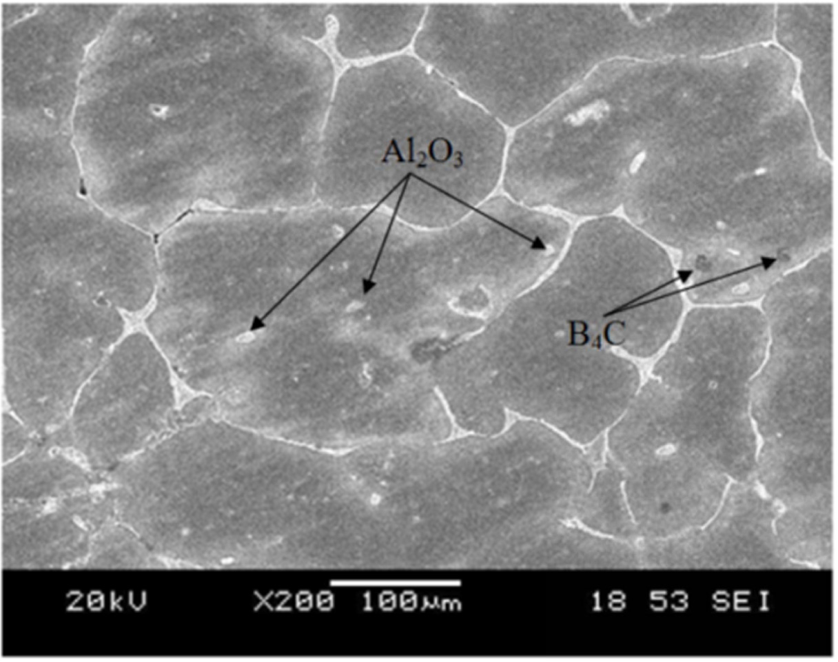
in cast specimens. X-ray Diffraction technique was employed
to ensure the presence of base alloy and its dispersed reinforcements.
Fig. 2 represents the SEM micrographs of Al 7075/ Al2O3/B4C
composites. It is evidently exposed that the dispersion of the particulates are
embedded into the Al 7075 aluminium matrix. Further the image reveals the
homogeneity of reinforcement in the specimen which indicates the
effectiveness of dispersion of the particulates during
stirring. XRD of the cast specimen Fig. 3 confirms the presence of Al2O3
and B4C particulates in the composites.
Wear
Test
Dry sliding wear behaviour of hybrid composite specimens
was investigated using Ducom TR 20 pin on disc apparatus as per ASTM G99
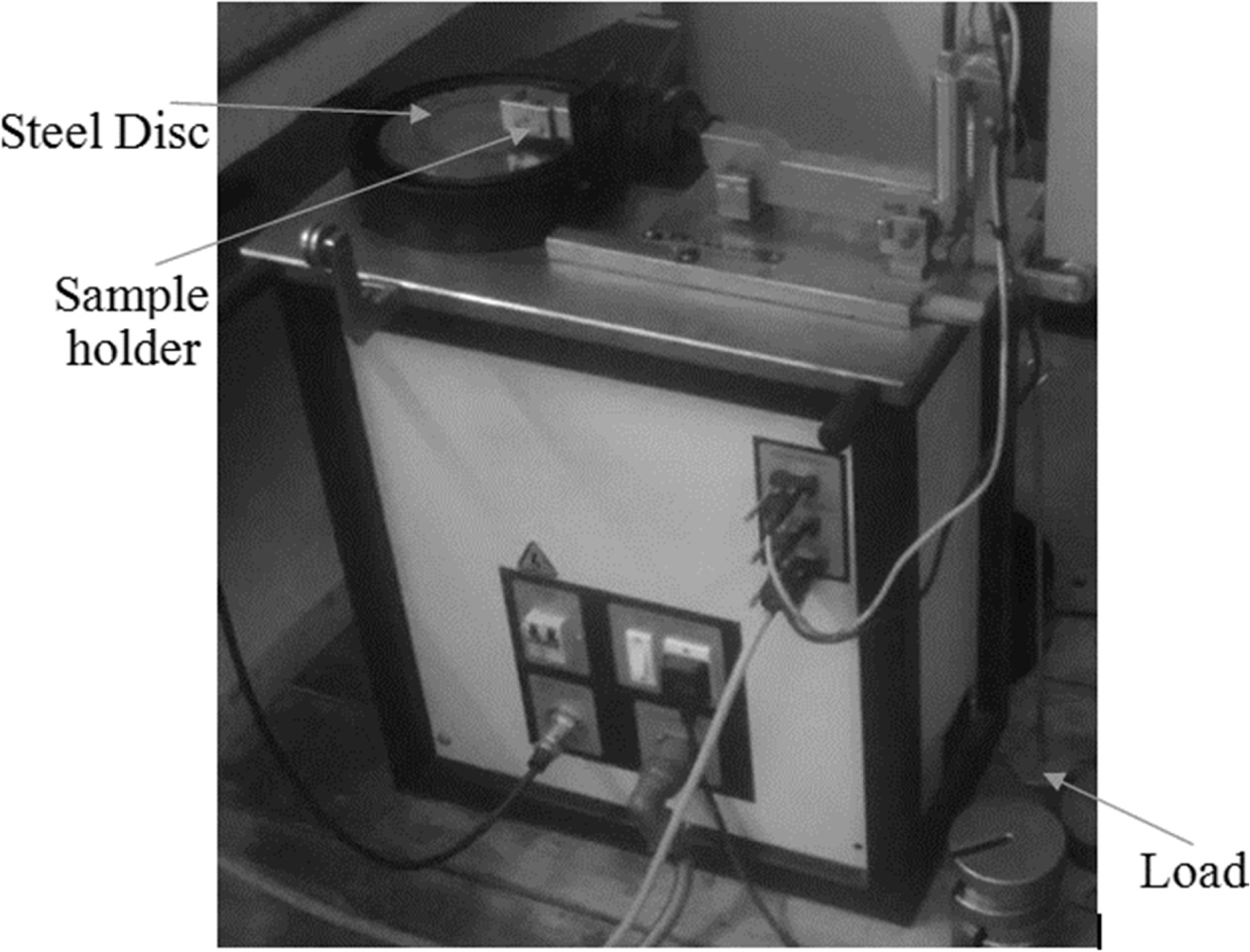
standards. The wear testing machine is shown in Fig. 4.
The specimens were machined for 10mm in diameter and
40mm in length and polished with emery paper of grade 600,
800, and 1,000 respectively. The cast pins were then pressed against an EN32
steel disc of surface roughness 1.2 µm and a hardness of 65HRC at room
temperature. The frictional forces were documented during the
entire wear experiments and average value was recorded.
The initial weight of the sample was measured using an electronic weighing
machine (SHIMADZU BL-220H) with the accuracy of 0.01mg. The pin
was weighed before and after testing to find out the amount of weight loss. The
wear rate was calculated using the eq. (1) based on the mass loss
where W is the wear rate (mm3/m),
M is mass loss (g), ρ is the density (g/mm3) and D
is the sliding distance (m).
The co-efficient of friction was determined by dividing
normal force against frictional force. The Dry sliding wear test were conducted
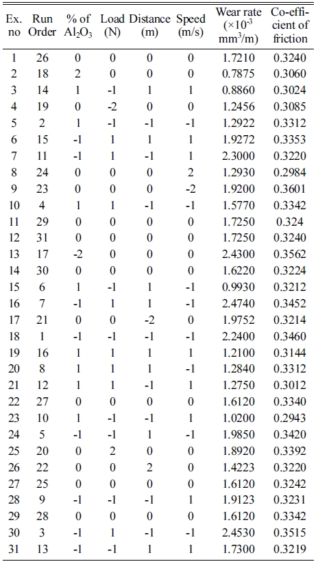
as per the design matrix established is shown in Table 2.
|
Fig. 1 Stir casting setup. |
|
Fig. 2 SEM image of 4% Al2O3reinforced hybrid composites. |
|
Fig. 3 XRD Analysis of the hybrid composites. |
|
Fig. 4 Ducom TR 20 wear testing machine. |

Response
surface methodology
Response Surface methodology is a collection of mathematical and
statistical techniques used for empirical
model building. It identifies the relations between wear parameters and
response functions with minimal number of experiments [21]. Design Expert 10.0
was employed for designing the experiments and to study the influence of
parameters on wear rate and coefficient of friction of the hybrid composites.
The four factors that affect the wear rate and Coefficient of friction are % reinforcement (R), load (L),
sliding distance (D) and speed (S). A
central composite design (CCD) model was chosen to determine the dry sliding
wear behaviour of the cast composites. The levels of each factor were chosen as
2, -1, 0, 1 and 2 in the coded form. The sliding wear parameters and their levels
are given in Table 2. The trials were carried out as per the design matrix and
their responses are presented in Table 3.
Development
of mathematical model
A second order polynomial regression model is constructed
to predict the relationship between the parameters and their responses which
shown in eq. (2).
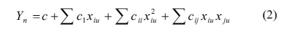
where Y is response c, ci,
cii and cij are coefficient respectively.
The response function representing the wear parameters,
namely, percentage as a function of reinforcement (R), load (L),
sliding speed (S) and sliding distance (D) can be
expressed as Y = f(R, L, S, D), where Y is the
response. A numerical model was developed using Design Expert Software
R10 and the regression coefficients are
calculated. The non-significance coefficients were curtailed and the
mathematical models developed for predicting the wear rate and coefficients of
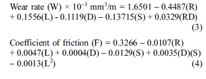
friction in coded form are given in eq. (3) and eq. (4).
Development
of mathematical model Normality of data
Normality of data is investigated by plotting a graph
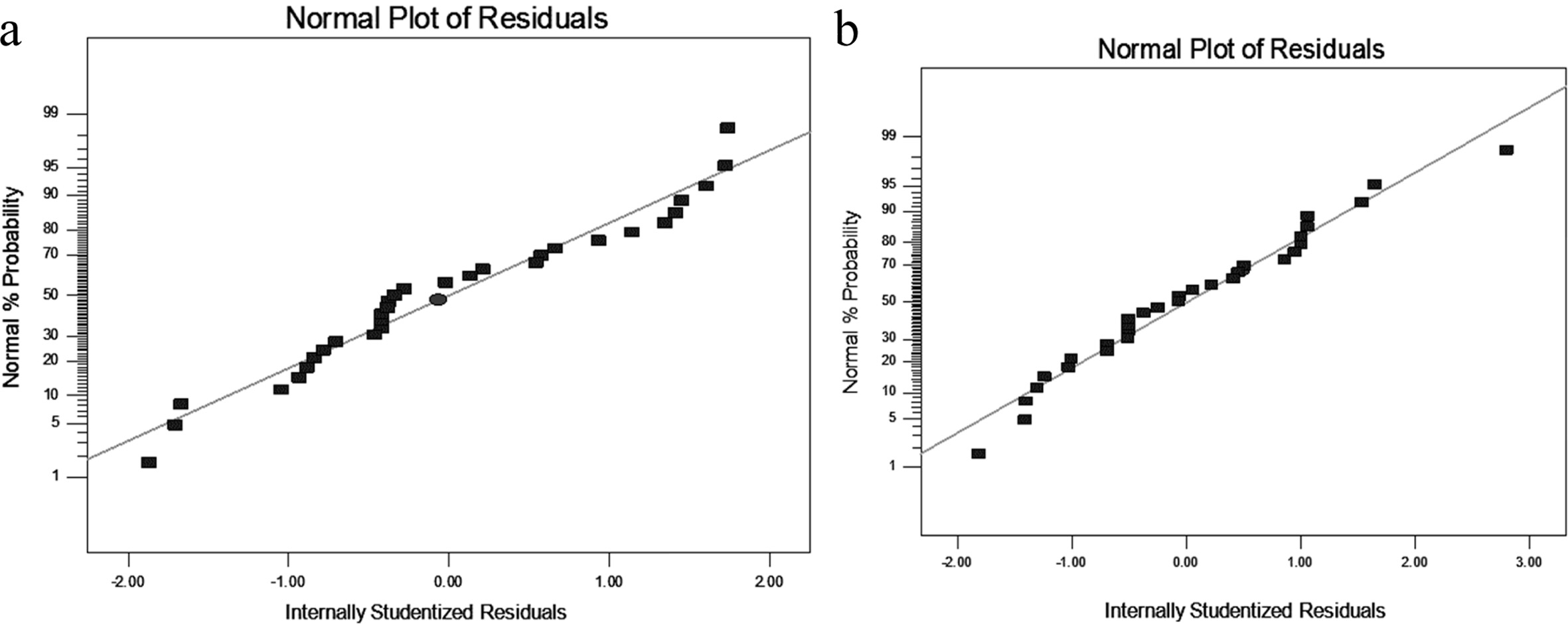
between the residuals and the normal probability [22]. The probability plot for
wear rate and coefficient of friction is shown in Fig. 5. From the plot it is
evident that the residuals fall on a straight line and the errors are
distributed in normal showing accuracy of the model.
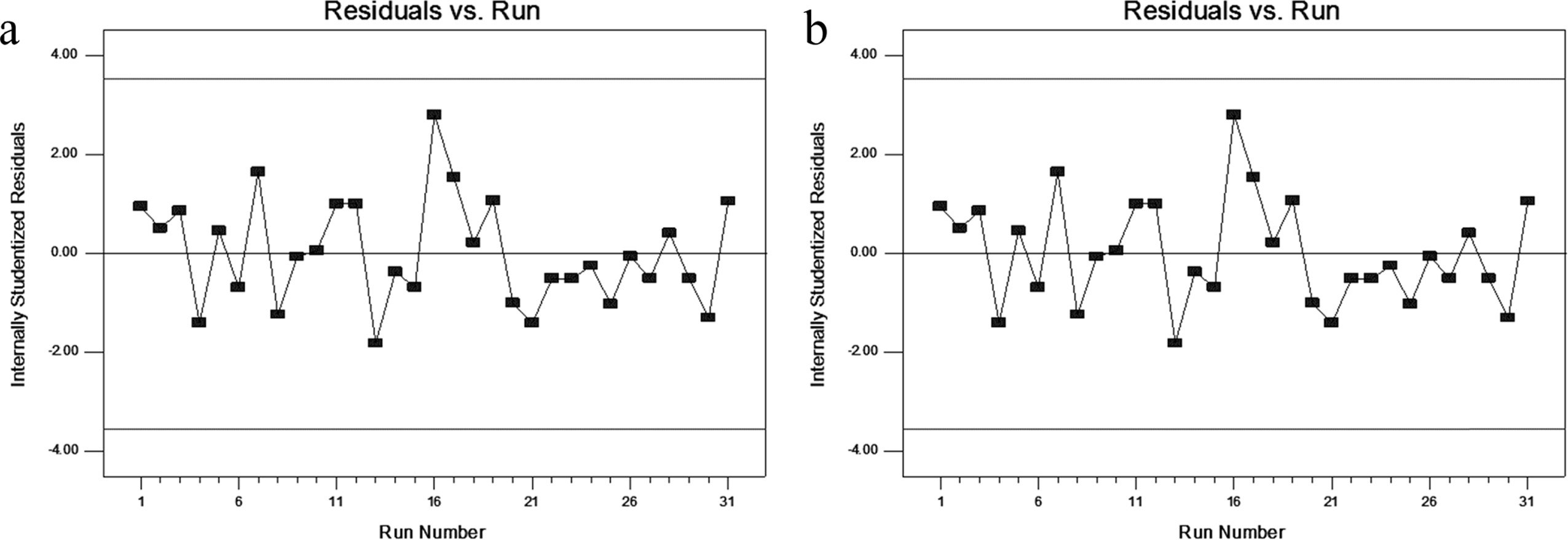
Independency of the data
Independency of the data was tested by means of residual
plot. This was done by plotting the residuals against run order [23]. Fig. 6,
shows the residual plot for wear rate and coefficient of friction respectively.
This plot depict that the no predictable pattern was observed because almost
all the residuals lies between -2 to 2 levels.
Analysis of variance
Adequacy of the developed model was checked using ANOVA
technique. The correlation coefficient (R2) indicates the goodness
of fits for the model [13]. In this work, the value of regression coefficient
(R2 = 0.9774) and adjusted regression coefficient
(adjusted R2 = 0.9728) indicates that only 5% of the total
variations are not explained by the model. The value of “Prob < F”, which
depicts that the model is statistically significant [24].
The ANOVA test results of wear rate were presented in
Table 4. The square of the regression coefficient (R2) value
0.9774 confirms that equation 3 is highly reliable. In addition
the computed F value = 174.72 is greater than the tabulated value F
(5, 25) = 3.85, suggesting that the test is more accurate. The P
value (< 0.0001) indicates that the empirical model is statistically
significantly [25].
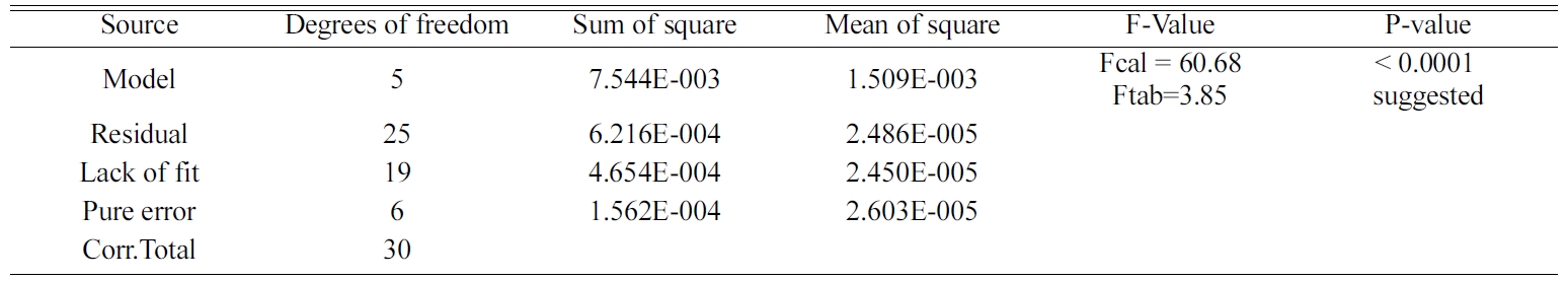
The ANOVA test results of coefficient of friction were
depicted in Table 5, the Square of the regression coefficient R2
value 0.9239 confirms that equation (4&5) is highly reliable. In addition,
the computed F value 60.68 is more than the tabulated value F (5, 25)
= 3.85, confirming that the test is significant. The P value
(< 0.0001) admits that the empirical model is significant. Thus the
proposed mathematical model could be used for the prediction of coefficient of
friction of the hybrid composites
|
Fig. 5 Normal probability plot (a) wear rate (b) coefficient of friction. |
|
Fig. 6 Residual plot (a) wear rate (b) coefficient of friction. |
|
Table 4 ANOVA results of wear rate using the mathematical model. |
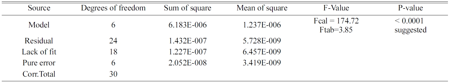
R2: 0.9774 adjusted R2: 0.9728 and predicted R2: 0.9631 |
|
Table 5 ANOVA results of coefficient of friction using the mathematical model. |
R2: 0.9239 adjusted R2: 0.9086 and predicted R2: 0.8839 |
Study
of Wear Behaviour of Al 7075/ Al2O3/B4C hybrid
composites
Fig. 7 & 8, represents the 3D interaction effect of
the input parameters on wear rate and coefficient of friction
on aluminium hybrid composites. From the equation (3 & 4), it can be
ascertained that the wear rate and coefficient of friction were fundamentally
influenced by reinforcement percentage and preceded by load, distance and
speed.
Effect of parameters on wear rate
The
influence of input parameters on wear rate is represented in Fig. 7. The effect
of reinforcements and load on wear rate was depicted in Fig. 7(b). The
inclusion of reinforced particulates in Al 7075 alloy decreased the wear rate compared with the base alloy. The wear rate
declined due to the reinforcements which act as a load bearing ingredients
thereby restricting the material removal in composites. Fig. 7(b), depicts a 2D
contour plot, with different colour, namely blue for minimum value, cyan for
medium value, green for high and red for very high value. The plot indicates
that wear rate increases with increase in load at minimum reinforced conditions.
A similar trend was observed by [26, 41] in their
work on adhesive wear behaviour of metal matrix composites. It is also
attributed that increase in reinforcement percentage increases the dislocation
density at the time of solidification process resulting in interruption of particle dislocation movement and improving the wear rate of the composites
[27].
The wear rate of the base alloy was higher than that of
the hybrid composites for all the load conditions. The surface plot depicts
that wear rate accelerated with increasing in load. An externally applied load
on to the cast samples with continuous contact on the counter face, deforms the
surface of the sample, which in turn leads to thermal softening of the specimen
and the wear regime changes from mild to severe wear. A similar
observation was recorded by [6] and [14] in wear study of Aluminium hybrid
composites. In summary, the % of reinforcements has negative effect on the wear
rate and it accelerates with the applied load
.
The influence of speed and distance on the wear rate is represented
in Fig. 7(c, d). The 3D surface plot and 2D counter plot indicates that the
wear rate declined with increasing speed and sliding distance. When the sliding
speed increases, a frictional heat was observed at the contact surfaces and a
molten layer was formed which in turn reduces the wear rate. It is also
recognized that the reinforcements bear a significant portion of load applied
on the composites during the test. At higher speeds the fragmented wear debris
particles are forced to combine with the specimen and form a mixed layer, which
in turn contribute to the better wear resistance. A similar type of behaviour
was observed by [28] & [29]. During increase of sliding distance the hard
ceramics available on the surface of the specimen were polish
ed out producing a lower wear rate. Abedini et al. [30]
reported that at higher sliding distance oxide layers were formed on the
surface which was the main reason for the declination of wear rate in the
hybrid composites.
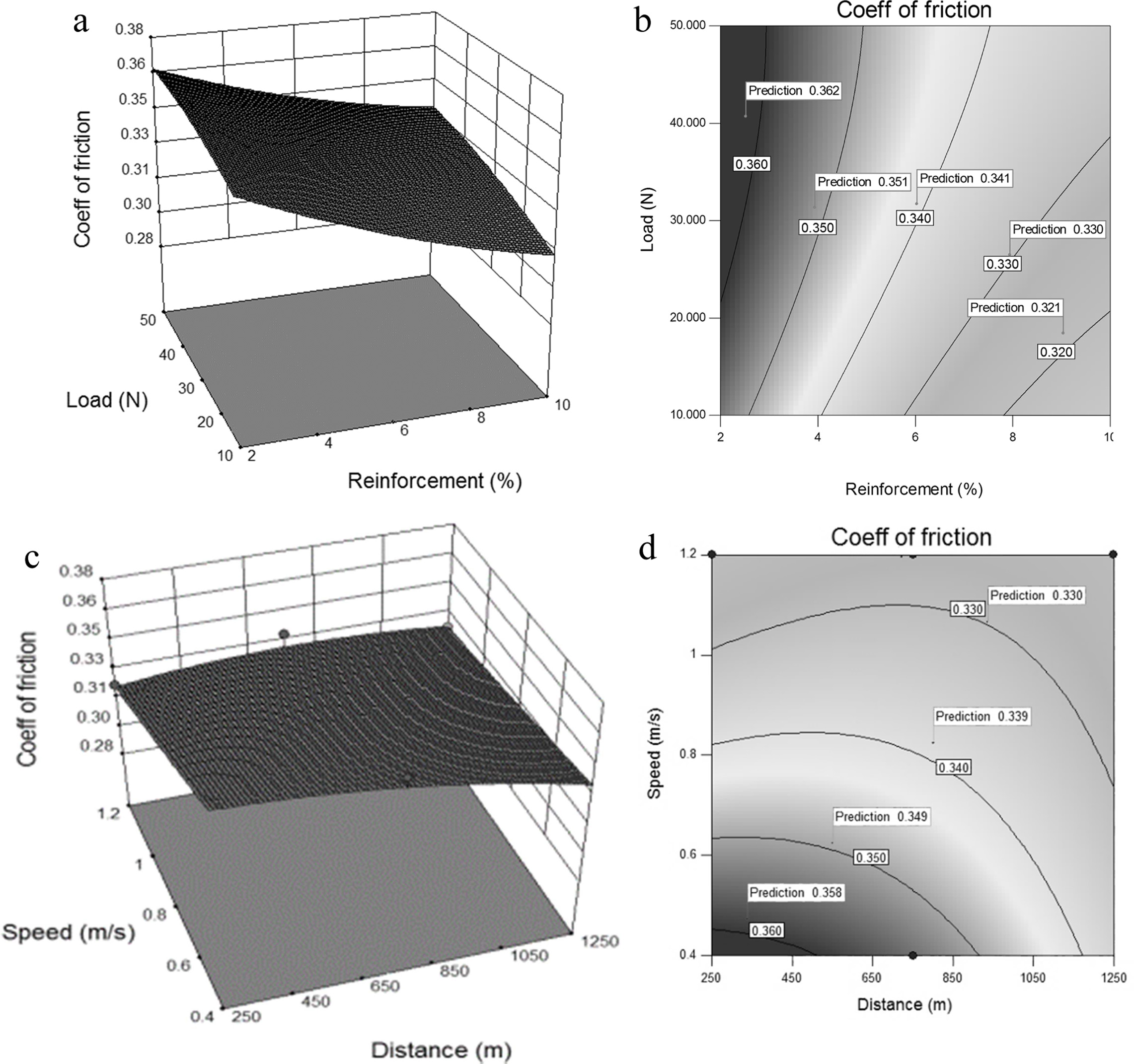
Effect of parameters on
coefficient of friction
The influence of input parameters on coefficient of friction
is represented in Fig. 8. The effect of reinforcement and
load was presented in Fig. 8(a, b). The chart depicts that
coefficient of friction decreases with addition of reinforcement. It may be
credited due to the addition of alumina and boron carbide to the base alloy
where the surface asperities prevent the counter face from mating with the
rotating disk. This reduces the coefficient of friction. A related result was
revealed by [31] in Al 7075/ SiC /B4C composites.
The coefficient of friction was increasing with respect
to the given load conditions. Initially coefficient of friction increases
gradually and it accelerates with the higher load conditions. Singh [32]
reported that at initial loads, an oxide layer was formed with low shear
strength and ductility which reduces the metal to metal contact. But at higher
load conditions the oxide layers were not capable of preventing metal to metal
contact resulting in higher coefficient of friction.
The influence of sliding speed and distance on coefficient
of friction is represented in Fig. 8(c, d). The 3d plot depicts that increase
in sliding speed decreases the coefficient of friction. At higher sliding speed
the specimen gets thermally softened due to increase in interfacial
temperature, which in turn leads to a lower coefficient of friction. These
results were well matched with [33] experimentation in Al/SiC/B4C
Composites. Similarly Hemanth et al. [34] pointed out that higher sliding speed
resulted to the lower coefficient of friction. The plot also indicates that
increase in sliding distance decreases the coefficient of friction. It may be
credited to the presence of Al2O3 and B4C
which cater abrasion resistance, resulting in negative effect to the coefficient
of friction. These results were well correlated with [35]
investigated in A390/Grp composites, second order polynomial
regression model is constructed is investigated by plotting a graph between the
residuals and the normal probability. The probability plot for wear rate and
coefficient of friction is shown in Fig. 5. From the plot it is evident that
the residuals fall on a straight line and the errors are distributed in normal
showing accuracy of the model.
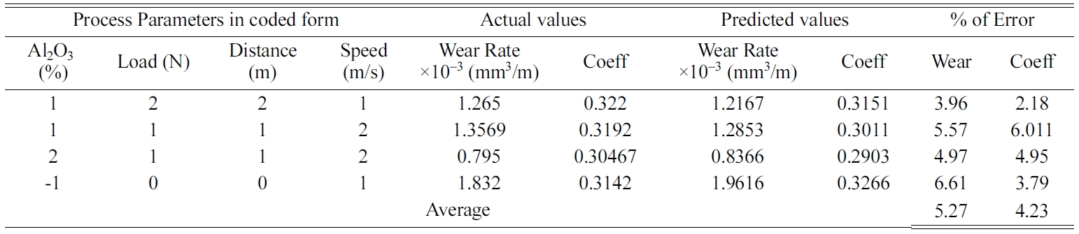
Validation
The mathematical models developed by regression analysis
were checked for their aqdequency using confirmation
experiments. The different input parameters, predicted
and actual responses were measured and reported in Table 6. From the results it
was evident that percentage of errors between the actual and the
predicted values were within the acceptable range. Hence the model
is highly efficient in predicting the wear rate and coefficient of friction
with 95% confidence level.
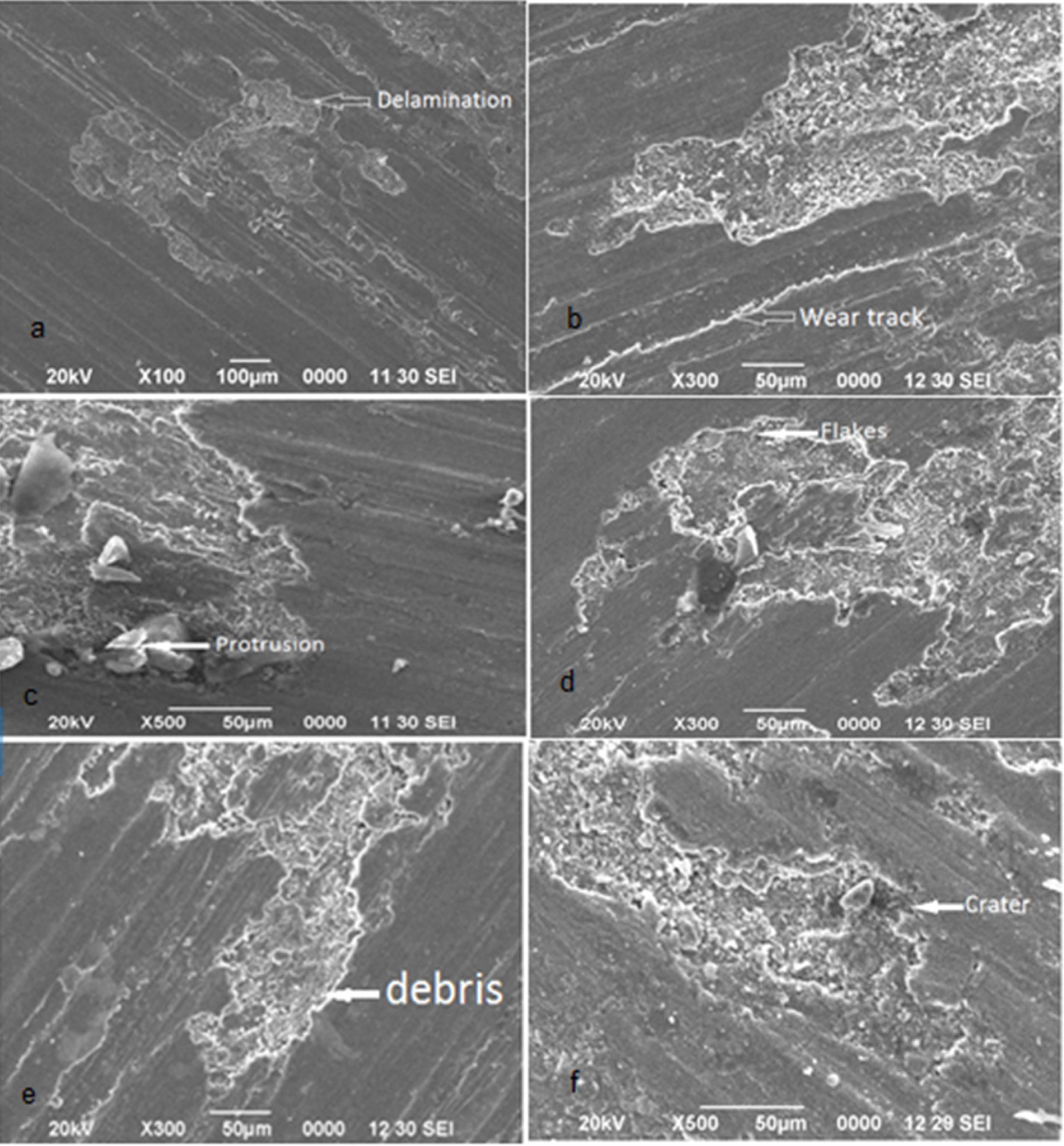
SEM
Analysis
Scanning Electron Microscope (SEM) studies of the worn
specimens were carried out using JOE JSM 6360 make equipment. It can be
observed from Fig. 9(a) that the composite with 2% Al2O3
was characterized by delamination type of wear due to the adhesion between the
composite pin and the disc surface. This is due to the presence of fewer
amounts of Al2O3 particles in the composite leading to
the higher material removal from the
surface. Uthayakumar et al. [12] studied the micrograph of Al/SiC/B4C
composites and the results were well agreed with above observations. With an increase in Al2O3 it can be
observed that the delamination type
of wear behaviour was transformed to abrasive type of wear mechanism due the
increase in Al2O3 and B4C particle content
(Fig. 9(a-f)). The abrasive type of wear
mechanism is characterised by plastic deformation whereas the delamination is due to elastic deformation.
Decrease in wear rate is due to the increased bonding
strength between the Al2O3 and the aluminium matrix
defending the composite surface against delamination. The presence of shallow
wear grooves running parallel to the direction of loading was established along
the surface of the specimen (Fig. 9(b-c)). This is due to the ploughing of the
fractured Al2O3 particles along the surface in the form
of wear debris. With a further increase in Al2O3 to 6%
(Fig. 9(d-f)) and greater, the presence of both abrasive wear and delamination
in the form of patches were observed along the surface. This can be correlated
to the ANOVA results that increase in Al2O3 and B4C
decreases the wear rate.
Higher wear rate at higher loads was characterised due
to the formation of crater in addition to the abrasive wear (Fig.
9(f)). The protrusion of the Al2O3 particles is also
evidenced in the composite specimen at higher loads (Fig. 9(c)). This confirms
the results observed in Fig. 9(d) that an increase in load increases the wear
behaviour of the composite. Selvi et al. [16] reported that high abrasive wear
occurs at higher loads. The formation of debris in the form of flakes was prime
mechanism at higher speeds due to the thermal softening
of the material leading to a decrease in wear rate as shown in Fig. 7(c). This
may due to the fact that with an increase in sliding speed, the effective
indentation due to the Al2O3 particles will be reduced
due to the entrapment of the debris in the space between the Al2O3
present in the composite.
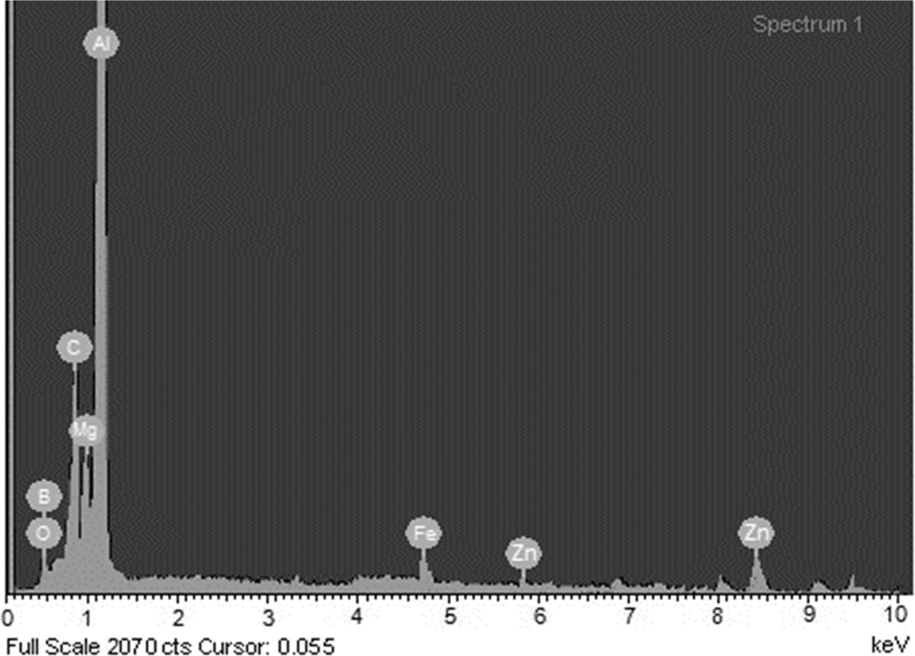
The worn surface of the hybrid composite under 20N load
was analysed using energy dispersive spectrometer (EDS).
Fig. 10 shows the EDS plot of 4% Al2O3
reinforced composite. The presence of Fe indicates the
transfer of iron from the counter disc to worn surface of the
specimen which results in forming of mechanically mixed layer
on the wear surface. Oxygen present in the composite confirms the oxidation reaction,
which in turn reduces the wear rate.
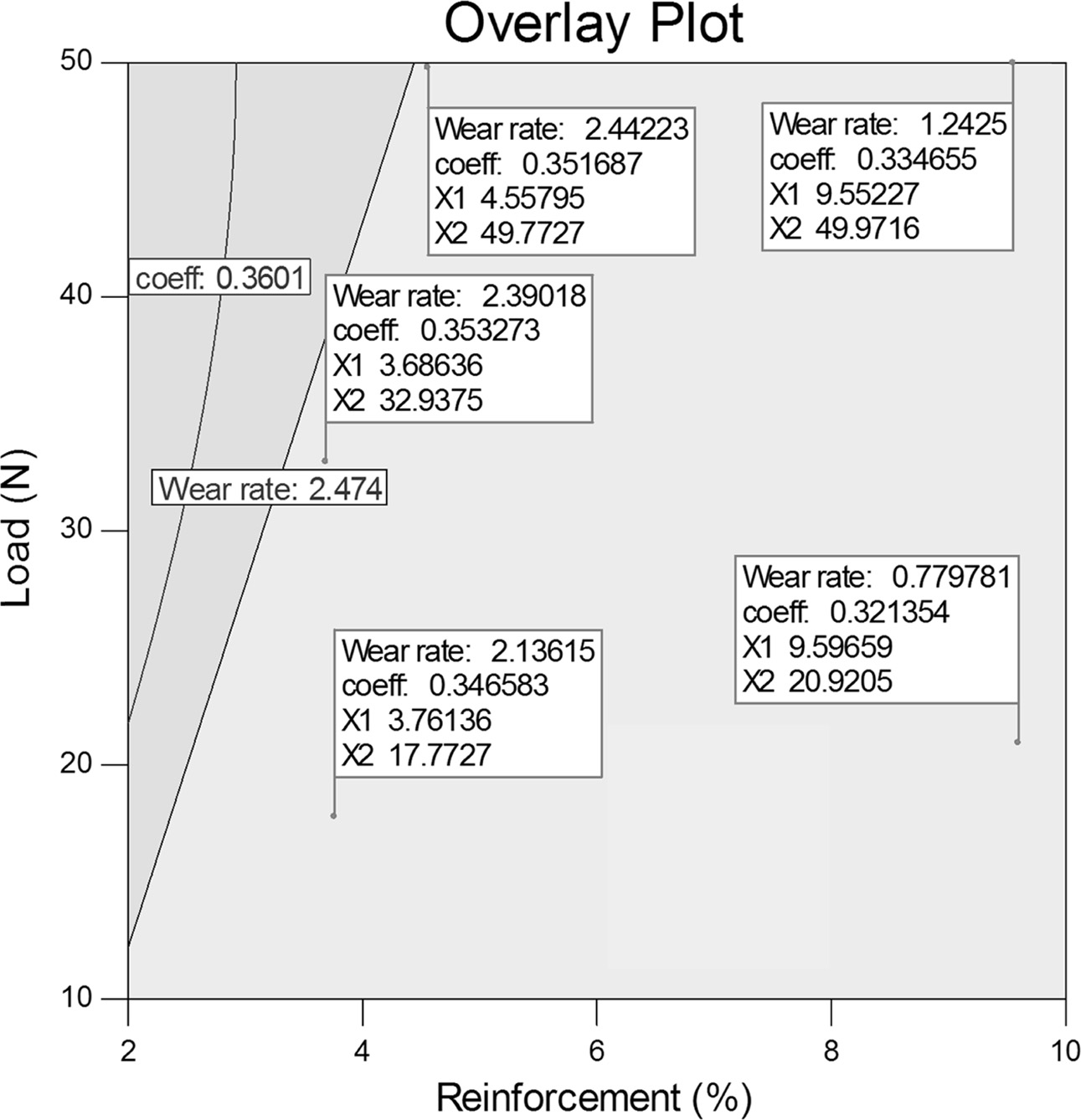
Fig. 11 shows the overlay
contour plot wear of Al/ Al2O3/B4C hybrid
composites in terms of % reinforcement in abscissa and load in ordinate. It is evident from
the plot that wear rate of hybrid composites continuously declines with
increase in reinforcement % for all load conditions. It is also observed that the wear rate
improved with increase in load for any
amount of reinforcements. The wear rate increases from 2.136 to 2.390 for an
increase in load (X2) from 17.7 to 32.9 for similar % reinforcement (X1). It is
credited to the third body abrasion of pull out and protruded particulates
which can be observed in Fig. 9(c). The coefficient of friction is reduced with increase in
load and % of reinforcement. It may be attributed that the reinforced ceramics
prevents the mating between the specimen and the disc, which in turn reduces
the coefficient of friction.
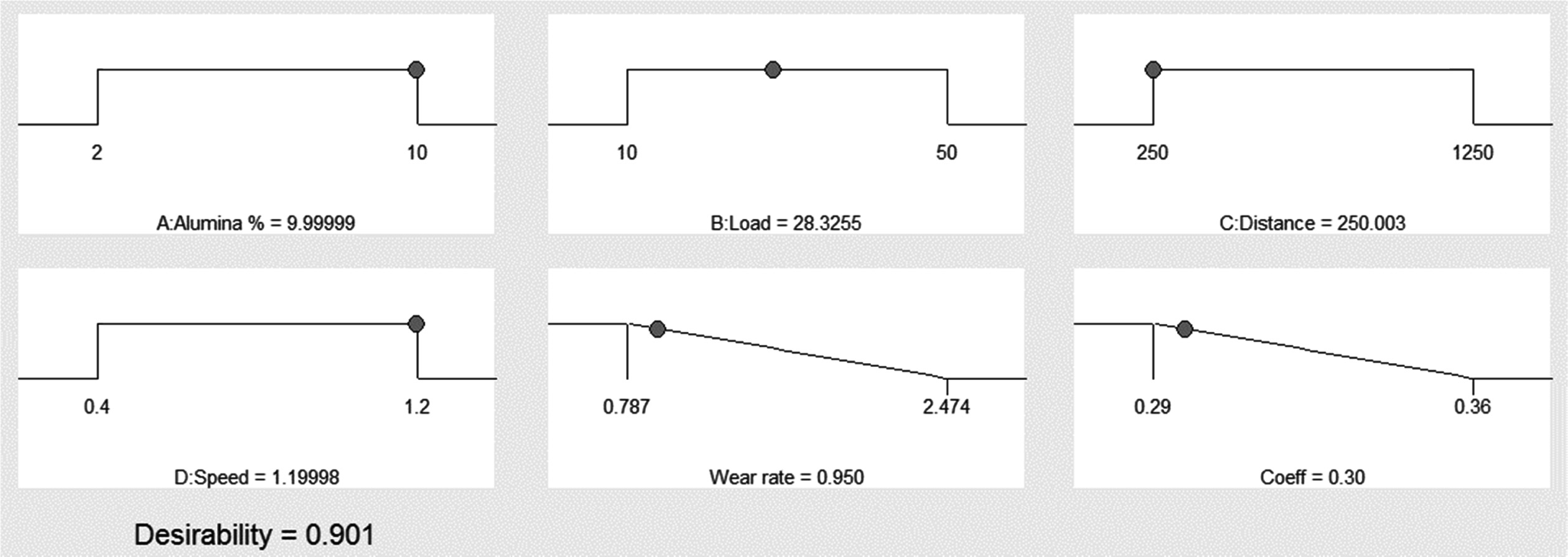
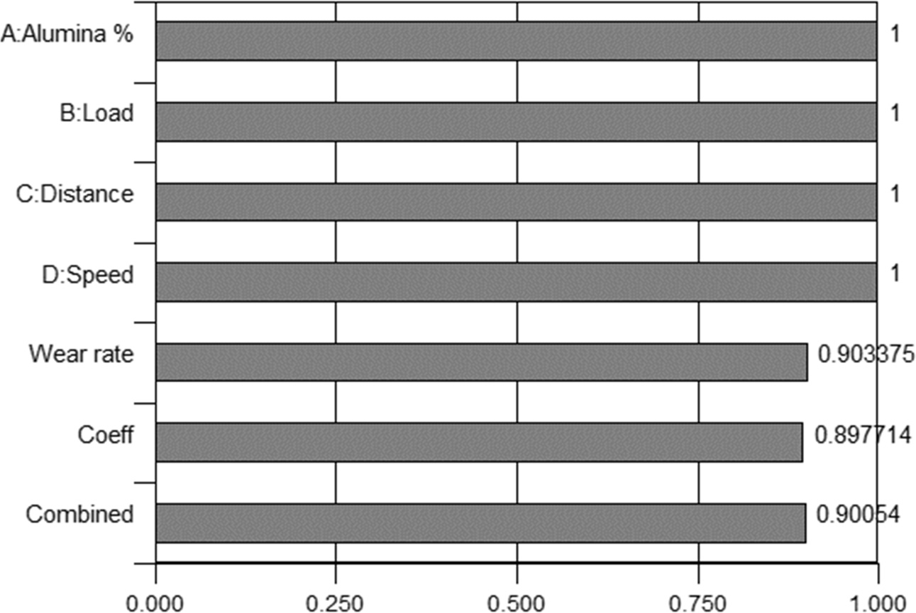
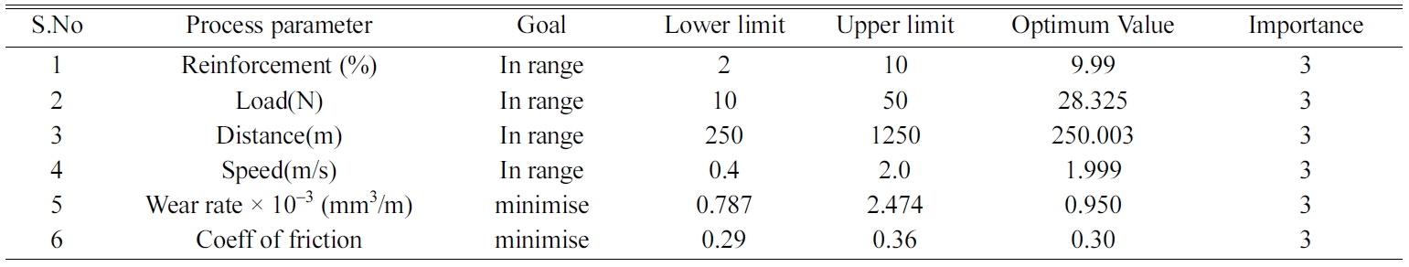
Desirability Based Multi Response Optimization
It is a challenging task to select the optimal process parameter
combinations for achieving improved wear rate and coefficient friction. Girish
et al. [36] employed Taguchi experimental design to
optimise the tribological parameters on wear rate. Derringer
et al. [37] explained a novel procedure on multiple response optimization named
Desirability approach. It is a smart technique used for optimizing the multiple
response problems. An objective function is created named desirability function
is transformed to an estimated response called desirability, which ranges from
0 to 1. The range respresents from least to the ideal case.
Gopalakannan et al. [19] applied combined central composite design and desirability
approach to improve the EDM characteristics of
aluminium matrix composites. The desirability evaluation was
done using Design Expert 10.0 software. In this study RSM was the
tool used to derive the optimized wear rate and coefficient of
friction values. Table 7 depicts the goals, range, optimal values
of the various input parameters and output responses ie. wear rate, coefficient
of friction. The analysis was made on 31 different input parameter pairs as
shown in Table 3. The input parameter pair with highest desirability value is
chosen as optimal condition for the output responses. The ramp function graph and
bar graph shown in Fig. 11, indicates the desirability of output responses. The
ramp function graph presents a clear picture on prediction
of response for particular parameters indicated by a dot. The bar graph (Fig.
13) represents the desirability values of each response and the combined
desirability of the model. The optimal region had a combined desirability
of 0.90054 which is an indication of closeness to the
response target. Fig. 12
|
Fig. 7 (a-d). Interaction plot for wear rate (a, b) 2D Contour plot (c, d). |
|
Fig. 8 (a-d). Interaction plot for coefficient of friction (a, b) 2D Contour plot (c, d). |
|
Fig. 9 (a-f). Worn Surfaces of Al Hybrid composite specimen under various conditions. |
|
Fig. 10 EDS analysis of worn surface at a load of 20N with 4% Al2O3. |
|
Fig. 11 Over lay counter plot for the effect on wear rate and coefficient of friction. |
|
Fig. 12 Ramp function graph of desirability. |
|
Fig. 13 Bar graph of desirability. |
|
Table 6 Mathematical comparison of actual and predicted results of wear rate and coefficient of friction model. |
Aluminum alloy reinforced with Al2O3
and B4C of different compositions were prepared by stir casting
method. The wear and frictional behaviour of the specimen were studied using
pin-on-disc equipment. The major outcome of the current investigations is
summarised.
• Al 7075/Al2O3/B4C matrix composite were manufactured successfully with a uniform dispersion of
particulates in the matrix which was authenticated by the SEM micro graph and
XRD.
• RSM Box Behnken design method was
employed to develop the model with 95% confidence level.
• A numerical model was developed to
predict the wear rate and coefficient of friction of aluminium hybrid
composites incorporating the effects of percentage of Alumina, sliding
distance, applied load, and sliding speed.
• The adequacy of the proposed model
was checked using ANOVA method. The result indicates that the developed model
has good agreement with the experimental results.
• The 3D interaction plot illustrate
that the wear rate decreases with increasing of
• Al2O3 content and incremented in increasing of load. The
wear rate has a negative impact in increase of sliding speed and sliding
distance.
• The coefficient of friction exhibited
an inversely proportional relationship with the percentage of reinforcement and
sliding speed.
• The input parameters were optimised
by adopting Desirability based multi response optimization to minimize the wear
rate and coefficient of friction.
• The optimum parameters of combination
is % of Alumina 9.99, Load 28.32 N, Sliding distance 250 m, Sliding speed 1.99
m/s, for a minimized wear rate of 0.950X 10⁻³
mm3/m and coefficient of friction 0.30 with a combined desirability
of 0.901.
- 1. M.K. Surappa, Sadhana 28[1-2] (2003) 319-334.
-

- 2. D.B. Miracle, Compos. Sci. Technol. 65[15-16] (2005) 2526-2540.
-
- 3. J. Eliasson and R. Standstorm, Key Engg Materials 104-107 (1995) 3-36.
-
- 4. M.O. Bodunrin, K.K. Alaneme, and L.H. Chown, J. of Mater. Res. Technol. 4[4] (2015) 434-445.
-
- 5. J. Hashim, L. Looney, and M.S.J. Hashm, J. Mater. Process. Technol. 92-93 (1999) 1-7.
-
- 6. A. Baradeswaran and A. Elaya Perumal, Compos.: Part B 56 (2014) 464-471
-
- 7. G.B. Veeresh Kumar, C.S.P Rao, N. Selvaraj, and M.S. Bhagyashekar, J. of Miner. & Mater. Char. & Engg 9[1] (2010) 43-55.
-
- 8. K. Ravi Kumar, K.M. Mohanasundaram, G. Arumaikkannu, and R. Subramanian, Tribol. - Mater., Surf. & Inter. 6[1] (2012) 15-19.
-
- 9. D.S. Prasad and C. Shoba, J. of Mater. Res. and Technol. 3[2] (2014) 172-178.
-
- 10. R. Kumar and S. Chauhan, Measurement 65 (2015) 166-180.
-
- 11. T. Rajmohan, K. Palanikumar, and S. Ranganathan, Trans. of Nonferr, Metals Soc. of China 23 (2013) 2509-2517.
-
- 12. M. Uthayakumar, S. Aravindan, and K. Rajkumar Mater. and Des. 47 (2013) 456-464.
-
- 13. K.R. Kumar, K.M. Mohanasundaram, G. Arumaikkannu, and R. Subramanian, Sci. and Engg of Compos. Mater. 19 (2012) 247-253.
-
- 14. N. Radhika and R. Raghu, Tribol Letters, 59[2] (2015) 1-9.
-
- 15. K. Ravi kumar, K.M. Mohanasundaram, G. Arumaikkannu, and R. Subramanian, Tribol. Trans 55 (2012) 723-729.
-
- 16. S. Selvi and E. Rajasekar, J. of Mech. Science and Technol. 29[2] (2015) 785-792.
-
- 17. S. Suresh, N. Shenbaga Vinayaga Moorthi, S.C. Vettivel, and N. Selvakumar, Mater. and Design 59 (2014) 383-396.
-
- 18. V. Vembu and G .Ganesan, Defence Technol. 11[4] (2015) 390-395.
-
- 19. K. Ravi Kuamr and Nishasoms, Arabian J. of Sci. Eng. 44 (2018) 893-909.
-
- 20. K. Ravi Kumar and V.S. Sreebalaji, Tribol. 9[3] (2015) 128-136.
-
- 21. S.C. Vettivel, N. Selvakumar, R. Narayanasamy, and N. Leema, Mater. and Design, 50 (2013) 977-996.
-
- 22. A.K. Lakshminarayanan and V. Balasubramanian, Trans. of Nonferr. Met. Soc. of China 19[1] (2009) 9-18.
-
- 23. X. Wang, X. Song, M. Jiang, P. Li, Y. Hu, K. Wang, and H. Liu, Optics & Laser Technol. 44[3] (2012) 656-663.
-
- 24. S. Rajakumar, C. Muralidharan, and V. Balasubramanian, Trans. Nonferrous Met. Soc. China 20[10] (2010) 1863-1872.
-
- 25. K. Velmanirajan, A. Syed Abu Thaheer, R. Narayanasamy and C. Ahamed Basha, Mater. and Des. 4 (2012) 239-254.
-
- 26. N. Radhika, R. Subramanian, S. Venkat Prasat, and B. Anandavel, Indl. Lubr. and Tribol. 64[6] (2012) 359-366.
-
- 27. A. Mazahery and M.O. Shabani, Trans. Nonferrous Met. Soc. China 23[7] (2013) 1905-1914.
-
- 28. V.C. Uvaraja and N. Natarajan, J. Tribol. 135[2] (2013) 021101.
-
- 29. K.M. Shorowordi, A.S.M.A Haseeb, and J.P Celis, Wear 256[11-12] (2004) 1176-1181.
-
- 30. M. Abedini, H.M. Ghasemi, and M. Nili Ahmadabadi, Tribol. Transactions 55[5] (2012) 677-684.
-
- 31. V.C. Uvaraja and N. Natarajan, J. of Miner. and Mater. Char. and Engg. 11 (2012) 757-768.
-
- 32. M. Singh, B.K. Prasad, D.P. Mondal, and A.K. Jha, Tribol. Inter. 34[8] (2001) 557-567.
-
- 33. U. Soy, A. Demir, and F. Findik, Indl. Lubr. and Tribol. 63[5] (2011) 387-393.
-
- 34. J. Hemanth, Wear 258[11-12] (2005) 1732-1744.
-
- 35. T.S. Mahmoud, J. of Mech. Engg Science 222[2] (2008) 257-265.
-
- 36. B.M. Girish, B.M. Satish, Sadanand Sarapure, and Basawaraj, Metallur. and Mater. Trans. A 47[6] (2016) 3193-3200.
-
- 37. G. Derringer and R. Suich, J. of Qual. Technol. 12[3] (1980) 214-219.
-
- 38. K. Kaviyarasan, T. Pridhar, B. Sureshbabu, C. Boopathi, and R. Srinivasan, IOP Conf. Ser.: Mater. Sci. Eng. 402 (2018) 01-07.
-
- 39. B. Sureshbabu, G. Chandramohan, C. Boopathi, T. Pridhar, and R. Srinivasan, Int. J. Ceram. Process. Res. 19[1] (2018) 69-74.
- 40. C. Saravanan, S. Dinesh, P. Sakthivel, V. Vijayan, and B. Suresh Kumar, Mater. Today:. Proc. 21[1] (2020) 744-747.
-
- 41. A.E. Pramono, Int. J. Ceram. Process. Res. 20[1] (2019) 01-07.
-
 This Article
-
2020; 21(2): 131-142
Published on Apr 30, 2020
- 10.36410/jcpr.2020.21.2.131
- Received on Jul 12, 2019
- Revised on Jan 20, 2020
- Accepted on Jan 21, 2020
Services
- Abstract
introduction
experimental procedure
response surface methodology and mathematical modelling
results and discussion
conclusions
- References
- Full Text PDF
Shared
Correspondence to
- Pridhar. T
-
Department of Mechanical Engineering, Sri Krishna College of Technology, Coimbatore, India
Tel : +919790003531 - E-mail: preeth_t@rediffmail.com
Clean-Energy Research Institute(CRI), Hanyang University, 222, Wangsimni-ro, Seongdong-gu, Seoul, 04763, Korea
E-mail: jcpr@hanyang.ac.kr