


- Thermal shock resistance of TaC / SiC coatings on carbon/carbon composites by the CVD process
Hyun-Mi Kima,b, Sung-Churl Choib, Yeontae Kimc, Hyung Ik Leec and Kyoon Choia,*
aEngineering Ceramic Center, KICET, Icheon, 17303, Korea
bDivision of advanced Materials Science and Engineering, Hanyang Univ., Seoul, 04763, Korea
cThe 4th R&D Institute, Agency for Defense Development, Daejon, 34186, Korea
Carbon/carbon composites (C / C)
have been widely studied in the aerospace field given their excellent thermal
shock resistance and specific strength at high temperatures. However, they are
associated with the problem of rapid oxidization and deterioration under normal
atmospheric environments. In order to overcome these problems, chemical vapor
deposition (CVD) coatings of ultra-high temperature ceramics to C / C have
become an important technical step. In this study, TaC coatings on C / C were
carried out by a CFD simulation and a subsequent CVD process. A TaC monolayer
and a SiC / TaC / SiC / TaC multilayer were compared with respect to the degree
of thermal shock resistance, accomplished in this case with an arc heater. The
TaC monolayer was mostly delaminated on the horizontally oriented carbon
fibers, which resulted in sharpened carbon fibers and porous Ta2O5
layers. However, the multilayer structure showed a protective vitreous coating
due to the oxidation of the SiC layer, with the inner C / C successfully
protected by the porous Ta2O5 layer underneath. It can be
concluded that multilayer coatings of SiC / TaC / SiC / TaC can be more
effective for thermal shock and oxidation resistance capabilities of composites.
Keywords: Ultra high temperature ceramics, Chemical vapor deposition, Tantalum carbide, Thermal shock resistance
The C / C composite is a high-temperature structural
material with a low density level, a small coefficient of thermal expansion,
and high specific strength, making it an ideal material as a thermal barrier of
aircraft nose tips, leading edges and reentry vehicles. In most cases, however,
these applications require oxidation and ablation resistance and therefore
require an appropriate coating layer for the protection of the C / C [1]. UHTC
carbides such as TaC, HfC, and ZrC can be used in an oxidizing atmosphere
because they have not only high melting points of the carbides but also high
melting points after the oxidation of the carbides [2, 3]. After
oxidation, however, a porous layer is formed such that the inflow of
oxygen into the interior is inevitable. Accordingly, gastight
characteristics can be expected via the formation of a multilayer as opposed to
using this approach alone [4].
As a multilayer material that complements the oxidation
resistance of UHTC carbide, silicon-based phases such as SiC and MoSi2
can help maintain a suitable level of oxidation resistance [5, 6]. The
multilayer forms an SiO2-based amorphous layer that can
prevent permeation of a gas even when oxidized, thereby allowing the
internal C / C to be preserved at temperatures below 1400 degrees Celsius [2].
As a means of forming the UHTC carbide and silicon carbide multilayer, CVD [7],
SAPS (supersonic atmosphere plasma spraying) [8, 9], pack cementation
[10], and slurry coating [11], have been used. The simplest and most stable
method is to form a multi-coating layer by CVD.
In this study, the heat-resistant oxidation
characteristics of two coating layers of TaC and SiC / TaC / SiC /
TaC were compared based on TaC and SiC as protective coatings for the oxidation
and ablation of C / C. In addition, a computational fluid dynamics simulation
was used to improve the uniformity of the coating layer.
The raw materials and equipment used for the experiments
were detailed in a previously published paper [12, 13]. TaCl5 (99.5%, H.C.
Starck, Germany), used as a raw material, was put into a vaporizer using a
powder feeder capable of delivering the powder at a constant rate in the form
of a solid powder. As a carrier gas, hydrogen gas containing 5% CH4
was used, with the gas mixed with TaCl5 in the vaporizer at 230
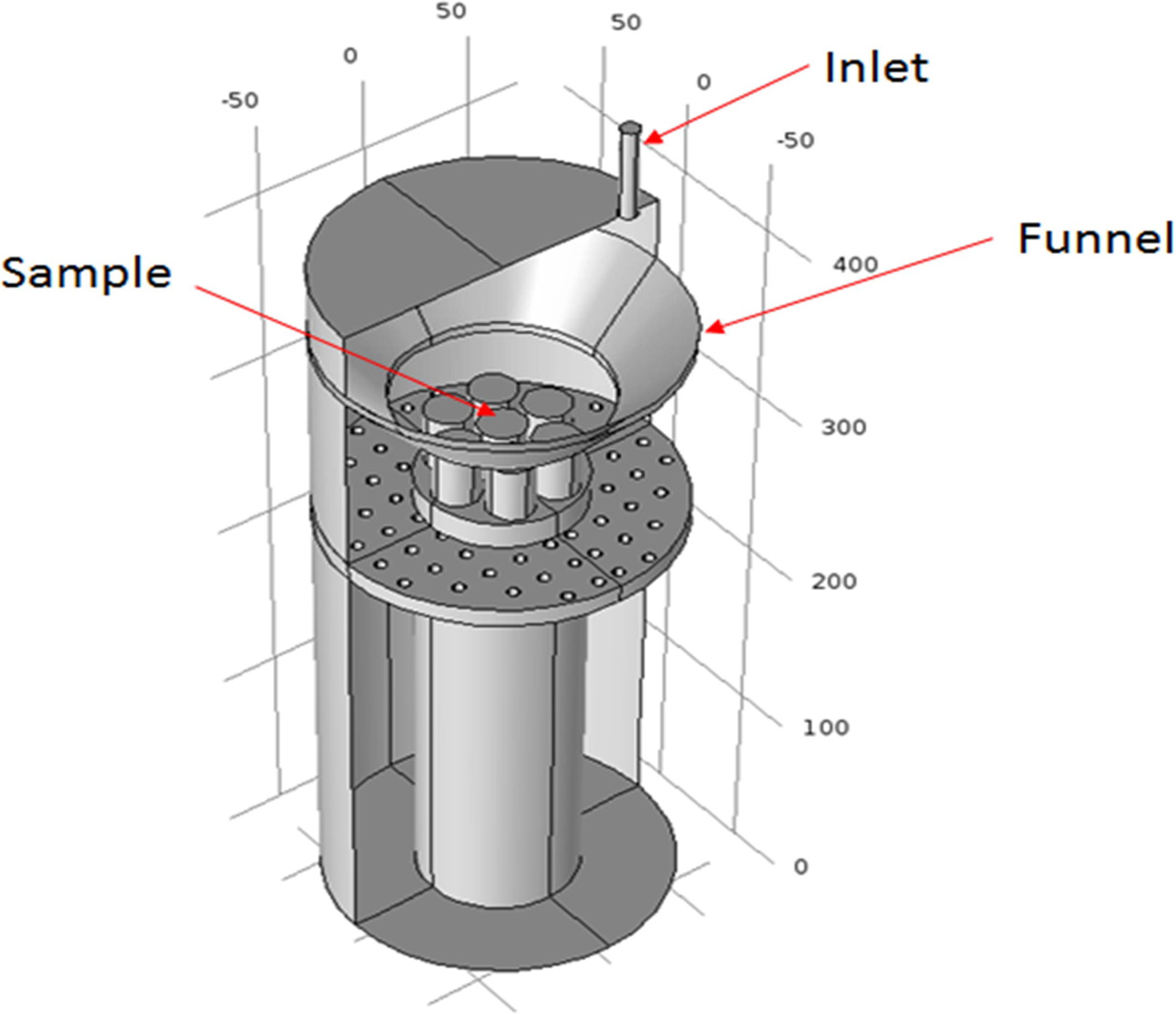
degrees Celsius and delivered along a heated gas line to the inlet, as shown in
Fig. 1.
The C / C sample was provided by DACC Co., Ltd. It was
cylindrical with a diameter of 15 mm and height of 50 mm. First, all samples
were coated with silicon carbide to a depth of 35 μm, after which 50 μm of TaC
or 50 μm of SiC / TaC / SiC / TaC were alternately raised and the
microstructures and heat resistance characteristics compared. The deposition
conditions for the silicon carbide and TaC are summarized in Table 1.
As shown in Table 1, hydrogen gas bubbling through a
bubbler containing an MTS liquid was transported to the reactor for the silicon
carbide, while the mixed hydrogen gas containing TaCl5 vapor
controlled by the powder feeder was provided for the tantalum carbide.
Therefore, the SiC / TaC multi-coating structure can be formed using deposition
processes alternately through two lines. The C / C composite sample
produced through this process was subjected to a thermal shock test
using a 200 kW arc heater. After the surface was subjected to a phase analysis
by XRD, the components remaining on the surface were confirmed by FE-SEM and
EDS.
|
Fig. 1 Schematics of the sample location in the deposition chamber for the TaC and SiC coating. |
|
Table 1 Details of experimental conditions for SiC and TaC deposition processes. |

Phase
prediction with FactSage 6.2
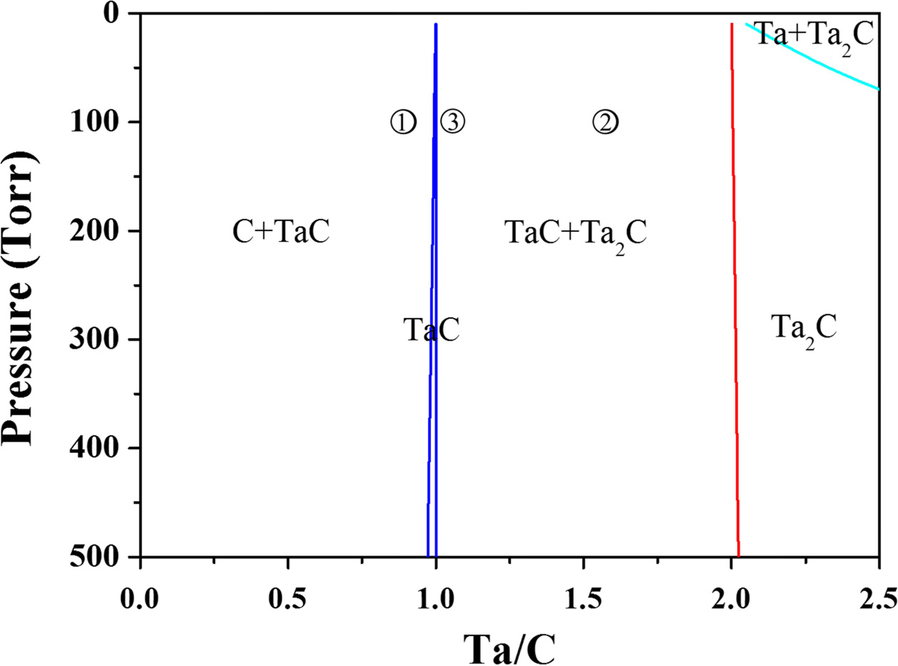
Fig. 2 shows the phase equilibrium when 5% CH4
containing hydrogen and TaCl5 are used as the raw materials. In this
system, a mixed phase of C and TaC or a mixed phase of TaC and Ta2C
is more easily obtained than a single TaC phase because the TaC single-phase
region is obtained only in a narrow region where the ratio of Ta and C is one.
Therefore, two microstructures were compared to determine the condition
under which the heat resistance characteristics are
expected to be better.
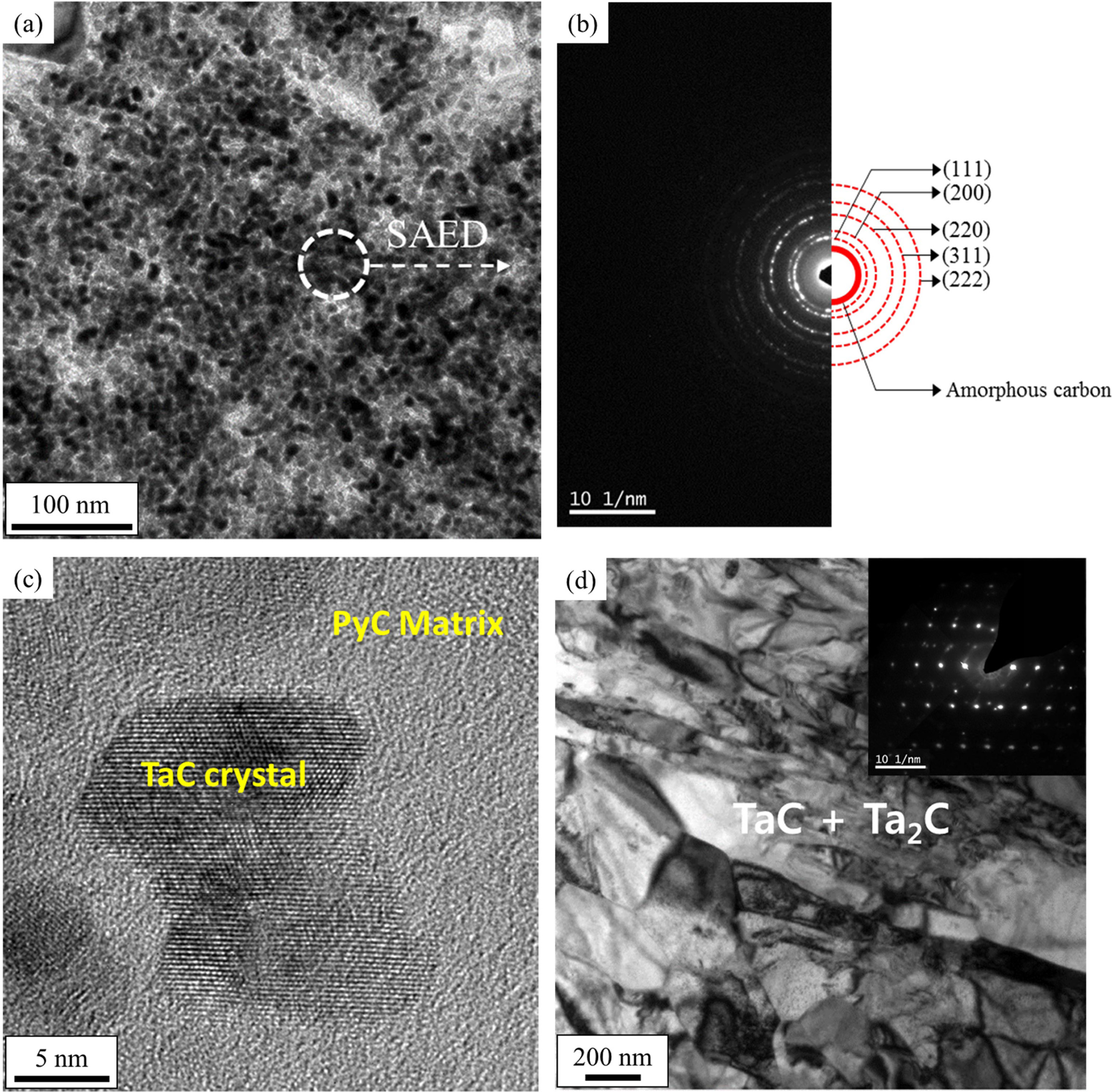
The microstructure obtained under the condition 1 shown in
Fig. 2 demonstrated a mixed phase of C and TaC, where small TaC crystals were
distributed in the pyrolytic carbon matrix, as shown in Fig. 3(a). This can
also be observed in the SAED pattern in Fig. 3(b) and in the HRTEM image in
Fig. 3(c), in which several nanometer-sized TaC crystals can be distinguished.
The microstructure is expected to be inadequate as an anti-ablation
coating due to the pyrolytic carbon constituting the matrix.
On the other hand, the microstructure obtained under condition 2 in Fig. 2
presents a mixed phase of TaC and Ta2C, in which case
micrometer-sized TaC and Ta2C crystals are homogeneously mixed. If
TaC and Ta2C crystals are mixed, each will likely prevent the growth
of the other to therefore maximize the heat resistance and anti-ablation
characteristics. Other studies [13-16] have reported that the heat-resistance
and anti-ablation properties of these types of coatings deteriorate when TaC
crystals grow in the form of a columnar structure. Therefore, the sample was
prepared under condition 3 in Fig. 2 because this condition utilized the
maximum amount of TaC for excellent ablation resistance while at the same time
suppressing the coarsening of the TaC crystals due to the small amount of Ta2C.
CFD
prediction for a uniform deposition
The sample holder was fabricated to deposit seven
cylindrical heat-resistant samples at the same time, and a funnel was installed
on top of it. The purpose of this installation was to reduce the
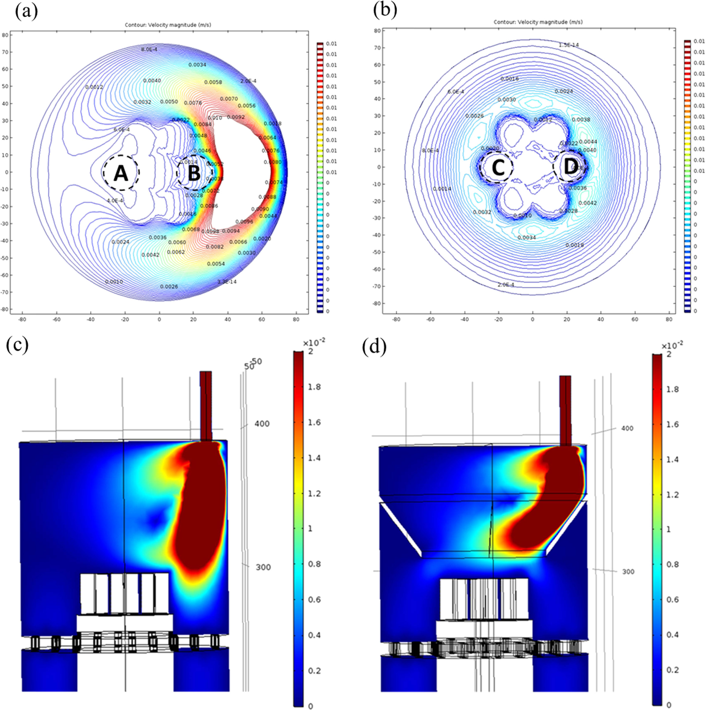
thickness deviation between the samples. The change of the flow
rate distribution before and after the installation of the funnel was confirmed
through a CFD analysis, the results of which are shown in Fig. 4. Checking the
velocity contours at positions “A” and “B” in Fig. 4(a), a steep slope of the
velocity is found at “B.” In contrast, the velocity distribution is much more
uniform in the “C” and “D” positions after the installation of the funnel, as
shown in Fig. 4(b). The reactant gas is well guided over the specimen by the
funnel to increase the deposition rate, as shown in Fig. 4(d).
TaC was deposited at positions “A” and “B” to demonstrate
experimentally the large difference in the flow velocity distributions in Fig.
4(a). A film of TaC with a small amount of Ta2C was formed after
four hours of deposition under condition 3 in Fig. 2. Significant differences
in the thickness at the “B” site were found at the right and left ends of the
sample, as shown in Figs. 5(a) and 5(b), respectively. On the other hand, at
the “A” site, a very thin TaC layer was identified, as shown in Fig. 5(c).
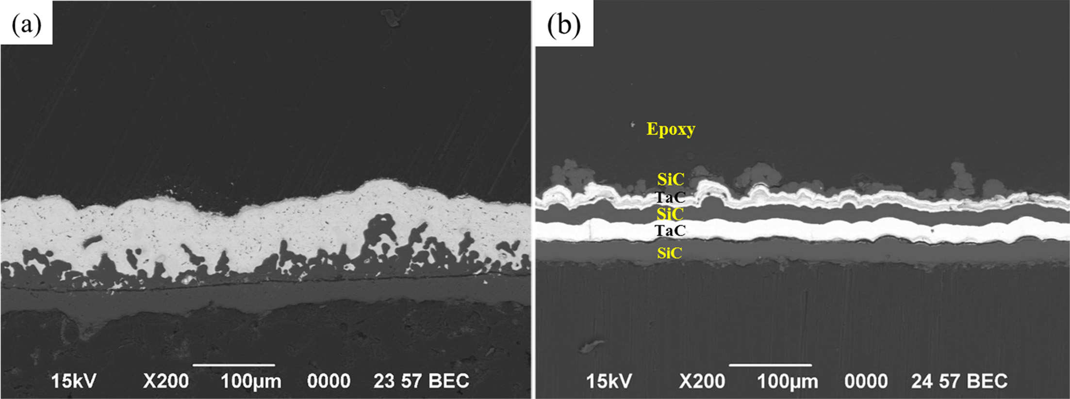
Deposition
of the TaC/SiC multilayer
The cross-sectional microstructures of the TaC layer and
the SiC / TaC / SiC / TaC multilayer are shown in Figs. 6, and
these are used in the high heat flow experiments. It can be seen that a coating
layer of approximately 80 to 100 μm is added onto the 35 μm SiC intermediate
layer on the C / C. Silicon carbide layers occasionally have irregular or
porous surfaces that appear to have complex interfaces with TaC.
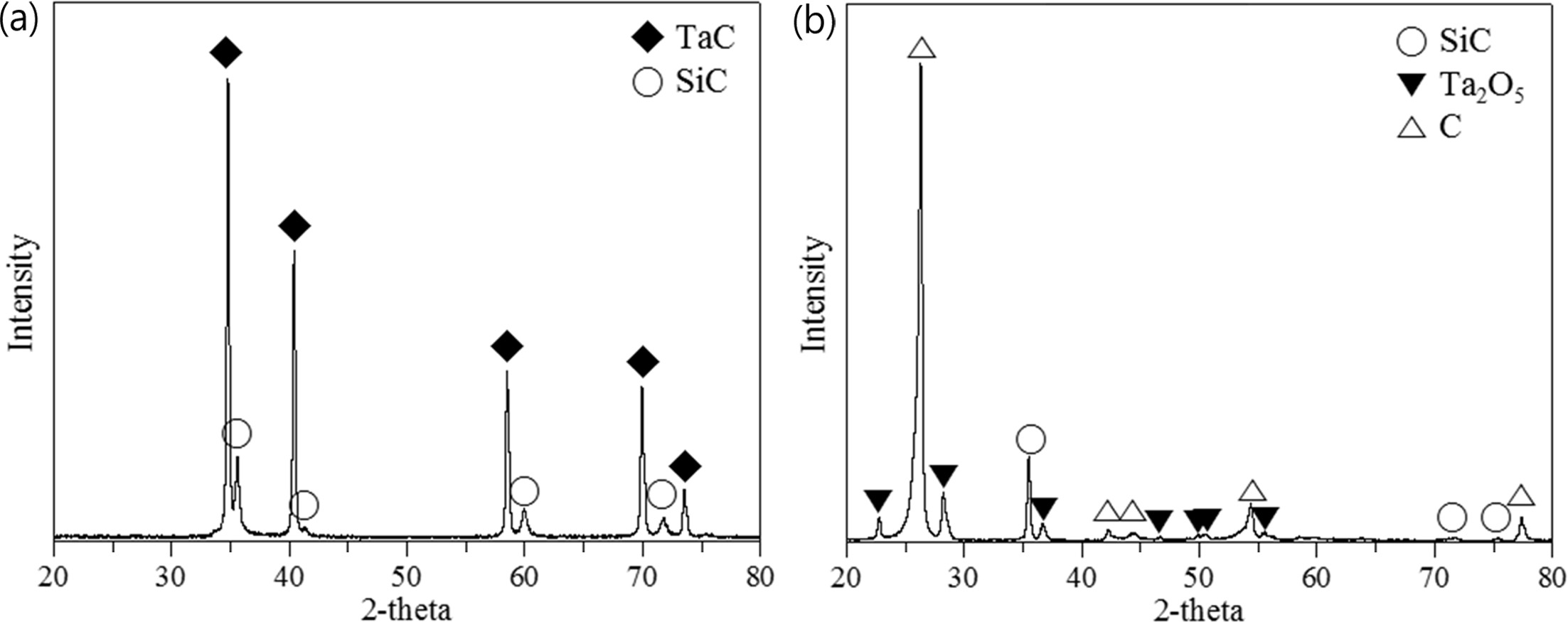
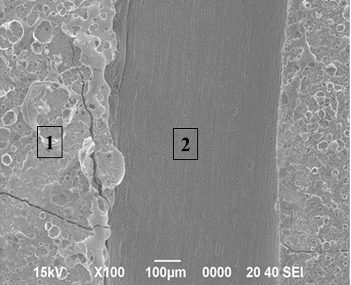
High
heat flux experiment on the TaC monolayer deposited C / C
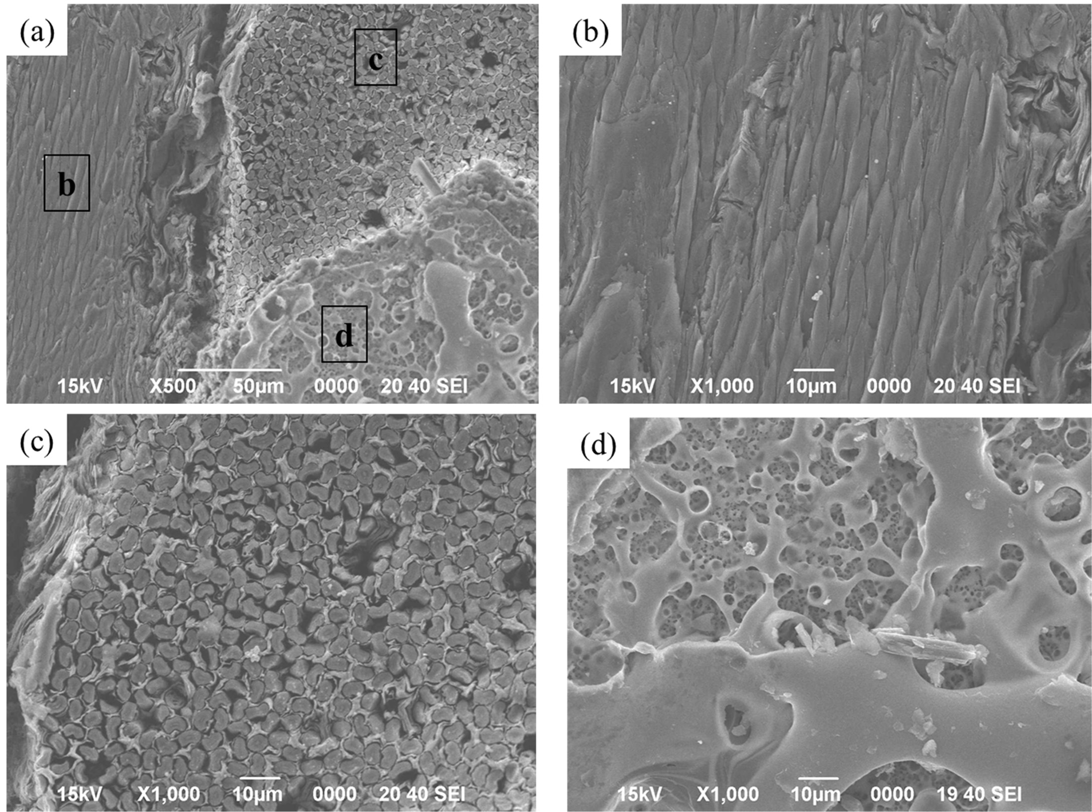
The sample of the TaC monolayer showed a severe appearance
change after the heat flux experiment. A large part of the coating layer had
peeled off, and the outer surface of the sample appeared to form a porous
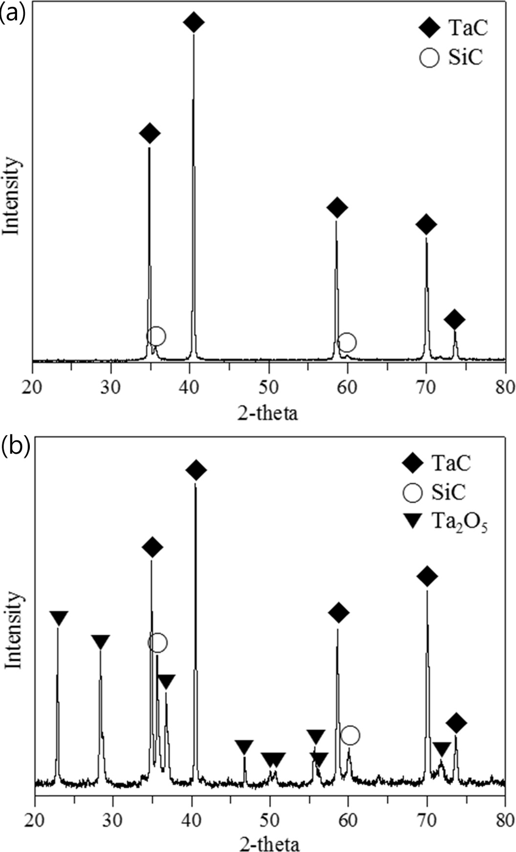
coating layer composed of the Ta2O5 crystal phase. This
is clearly observable in Fig. 7 in the XRD results, which shows
strong carbon peaks indicating the significant portion of C
/ C exposure, with only the Ta2O5 crystal phase and
underlying SiC layer identifiable. A long strap peeled off due to the large
difference in the thermal expansion coefficient between the coating layer and
the C / C, as shown in Fig. 8. Most of the C / C exposed areas are those in
which the carbon fibers are horizontally oriented. It was also confirmed that
the tip of the carbon fiber is sharply oxidized, as shown in Fig. 9(b). The carbon
fibers are thought to have been exposed at the beginning of the high heat flux
experiment. According to the weaving direction of the carbon fiber, it could be
confirmed as to whether the Ta2O5 layer is attached. It
was noted that Ta2O5, which appears as a bright area,
scarcely remains in the area where it horizontally comes into contact with the
carbon fiber.
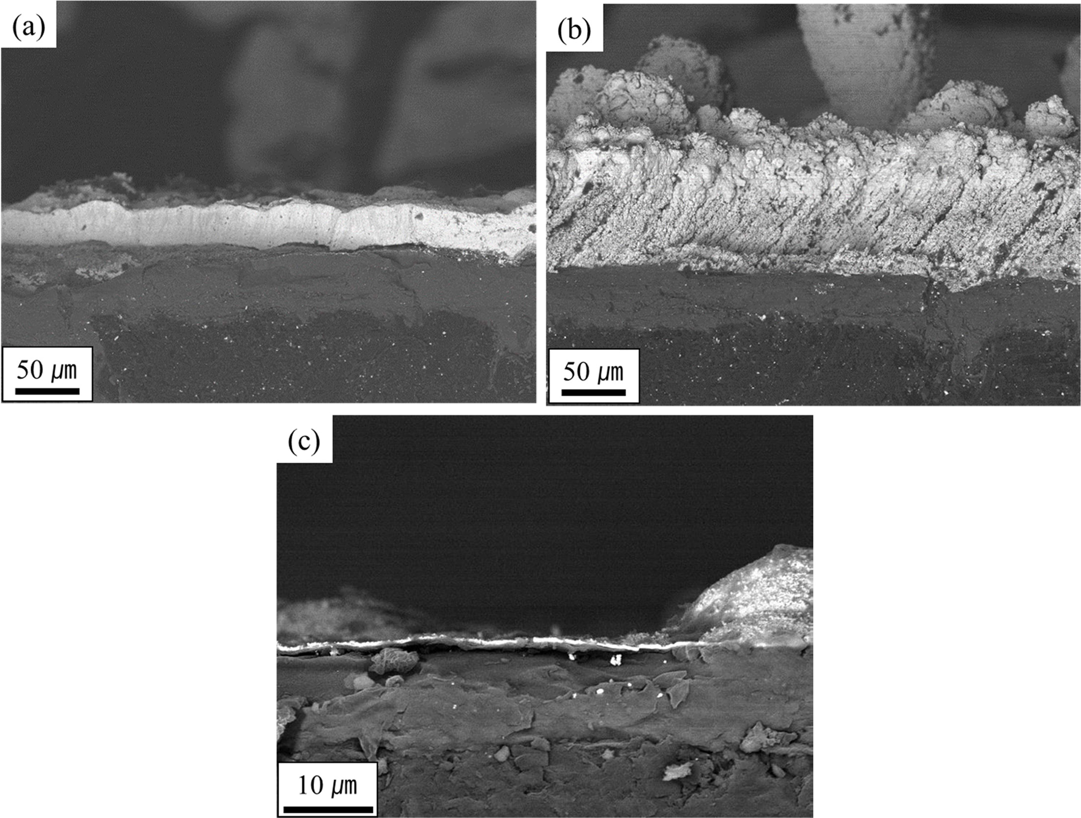
High
heat flux experiment on multilayer deposited C / C
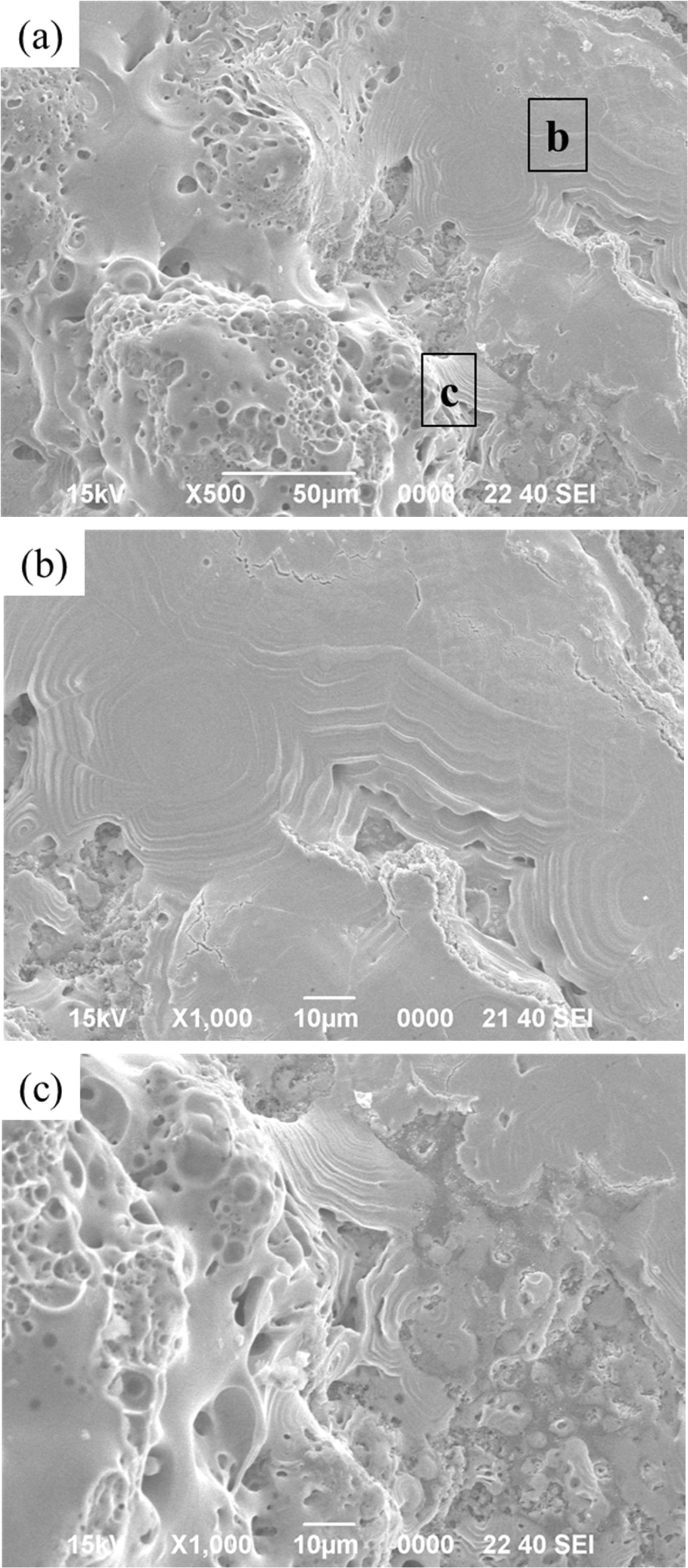
Fig. 10 shows the appearance after the high heat flux test
of the samples with the SiC / TaC / SiC / TaC multilayers to a thickness of 50 μm.
It was confirmed that a white oxide layer had formed along the outer edge of
the sample, with partial peeling also observed. The XRD results show that part
of the TaC layer was oxidized to Ta2O5 but that some TaC
remains robust under the SiC layer. The silicon carbide layer on the surface
was vitrified as it was oxidized, as shown in Fig. 11(b). With the flow of the
high heat flux, liquid silicate formed, appearing to flow
downward. Meanwhile, the TaC layer underneath is partially
oxidized to form a Ta2O5 layer. As shown in Fig. 11(c), it
has a porous appearance, similar to the microstructures observed
in other studies [17, 18]. It is estimated that the melting and covering
of the silicate glass on TaC protects against further oxidation of the TaC
layers, while the C / C can also be protected from oxidation.
|
Fig. 2 Thermodynamic phase diagram at 1200 oC with CH4 5% hydrogen and TaCl5 as the gas sources |
|
Fig. 3 TEM micrographs of (a) a specimen deposited under condition “1,” (b) corresponding SAED pattern, (c) high-resolution image, and (d) a sample deposited under condition “2” in Fig. 2. |
|
Fig. 4 Comparison of the surface velocity (a) without and (b) with the funnel designed to reduce the uniformity of the film thickness, and cross-sectional profile of the velocity distribution (c) without and (d) with the funnel. |
|
Fig. 5 Cross-sectional micrographs of (a) the left side and (b) right side of specimen “B” and (c) specimen “A” designated in Fig. 4(a). |
|
Fig. 6 Cross-sectional SEM micrographs of the (a) TaC layer and (b) SiC / TaC / SiC / TaC multilayer. |
|
Fig. 7 XRD results of the TaC layer (a) before and (b) after the high heat flux experiment. |
|
Fig. 8 SEM micrographs of the TaC layer showing local peel off regions after the high heat flux experiment. |
|
Fig. 9 SEM micrographs of the TaC layer after the high heat flux experiment: (a) surface and (b), (c), and (d) marked local magnifications of (a). |
|
Fig. 10 XRD results of the SiC / TaC / SiC / TaC multilayer (a) before and (b) after the high heat flux experiment. |
|
Fig. 11 SEM micrographs of the SiC / TaC / SiC / TaC multilayers after the high heat flux experiment: (a) surface and (b), (c) denoted local magnifications of (a). |
The combination of the oxidation resistance of SiC and the
abrasion resistance of TaC to form a new combination of UHTC coating layers has
been tried. TaC monolayers with a TaC phase containing trace amounts of the Ta2C
phase were CVD-coated on SiC-coated C / C and high thermal flux experiments
were carried out. After the high heat flux experiments, exfoliation of the TaC
layers occurred depending on the fiber arrangement of the C / C, with severe
morphological changes. One the other hand, the SiC / TaC / SiC / TaC
multilayers on SiC-coated C / C showed no delamination. For the
multilayer-coated samples, the internal TaC film mostly survived after the high
thermal flux experiments, most likely due to silicate formation caused by the
oxidation of the SiC top layer. Microstructures on which the liquid silicate
flowed down to a porous Ta2O5 layer were frequently
observed.
This work was supported by the Korean Government (Defense
Acquisition Program Administration, DAPA) through research institute (Agency
for Defense Development, ADD).
- 1. M.E. Westwood, J.D. Webster, R.J. Day, F.H. Hayes, and R. Taylor, J. Mater. Sci. 31[6] (1996) 1389-1397.
-

- 2. M.M. Opeka, I.G. Talmy, and J.A. Zaykoski, J. Mater. Sci. 39[19] (2004) 5887-5904.
-
- 3. E.L. Corral and R.E. Loehman, J. Am. Ceram. Soc. 91[5] (2008) 1495-1502.
-
- 4. F. Lamouroux, S. Bertrand, R. Pailler, and R. Naslain, Key Eng. Mater. 164 (1998) 365-368.
-
- 5. Q. Fu, X. Zou, Y. Chu, H. Li, J. Zou, and C. Gu, Vacuum 86[12] (2012) 1960-1963.
-
- 6. Y.-L. Zhang, H.-J. Li, X.-F. Qiang, K.-Z. Li, and S.-Y. Zhang, Corros. Sci. 53[11] (2011) 3840-3844.
-
- 7. G.-d. Li, X. Xiong, B.-y. Huang, and K.-l. Huang, Trans. Nonferrous Met. Soc. 18[2] (2008) 255-261.
-
- 8. Y. Zhang, H. Hu, P. Zhang, Z. Hu, H. Li, and L. Zhang, Surf. Coat. Tech. 300[25](2016)1-9.
-
- 9. Y. Zhang, Z. Hu, H. Li, and J. Ren, Ceram.Int. 40[9] (2014)14749-14755.
-
- 10. P. Wang, S. Zhou, P. Hu, G. Chen, X. Zhang, and W. Han, J. Alloy Compd. 682[15] (2016) 203-207.
-
- 11. S. Ramasamy, S.N. Tewari, and K.N. Lee, Mater. Sci. Eng. A 527[21-22] (2010) 5492–5498.
-
- 12. H.-M. Kim, K. B. Shim, J.-M. Lee, H.-I Lee, and K. Choi, J. Ceram. Proc. Res. 19[6] (2018) 519-524.
- 13. Y.-S. Jeong, K. Choi, and H.G. Yoon, J. Korean Ceram. Soc. 56[3] (2019) 291-297.
-
- 14. Y. Wang, X. Xiong, G. Li, Z. Chen, W. Sun, and X. Zhao, Corros. Sci. 65 (2012) 549-555.
-
- 15. Y. Wang, X. Xiong, G. Li, X. Zhao, Z. Chen, W. Sun, and Z. Wang, Solid State Sci. 20 (2013) 86-91.
-
- 16. Y. Wang, Z. Li, X. Xiong, X. Li, Z. Chen, and W. Sun, Appl. Surf. Sci. 390 (2016) 903-908.
-
- 17. C. Zhen, X. Xiong, G. Li, W. Sun, and Y. Long, Appl. Surf. Sci. 257 (2010) 656-661.
-
- 18. G. Li, X. Xiong, and K. Huang, Trans. Nonferrous Met. Soc. 18 (2008) s689-s695.
-
 This Article
-
2020; 21(1): 92-98
Published on Feb 28, 2020
- 10.36410/jcpr.2020.21.1.92
- Received on Oct 4, 2019
- Revised on Dec 24, 2019
- Accepted on Dec 26, 2019
Services
- Abstract
introduction
experimental
results and discussion
conclusion
- Acknowledgements
- References
- Full Text PDF
Shared
Correspondence to
- Kyoon Choi
-
Engineering Ceramic Center, KICET, Icheon, 17303, Korea
Tel : +82-31-645-1456 Fax: +82-31-645-1493 - E-mail: knchoi@kicet.re.kr
Clean-Energy Research Institute(CRI), Hanyang University, 222, Wangsimni-ro, Seongdong-gu, Seoul, 04763, Korea
E-mail: jcpr@hanyang.ac.kr