


- Development of MgFe2O4 as an oxygen carrier material for chemical looping hydrogen production
Jong Ha Hwanga and Ki-Tae Leeb,c,*
aDepartment of Mineral Resources and Energy Engineering, Jeonbuk National University, Jeonbuk 54896, Republic of Korea
bDivision of Advanced Materials Engineering, Jeonbuk National University, Jeonbuk 54896, Republic of Korea
cHydrogen and Fuel Cell Research Center, Jeonbuk National University, Jeonbuk 54896, Republic of Korea
Chemical looping hydrogen
production (CLHP) is an attractive technology for H2 production due
to its ability to produce H2 and capture CO2 from fossil
fuels simultaneously. In this paper, we present MgFe2O4
as an oxygen carrier material with high efficiency, low cost, and stable
properties for CLHP. The redox reactions occurred reversibly in the fuel,
steam, and air reactor as MgFe2O4→MgO/Fe, MgO/Fe→MgO/Fe3O4,
and MgO/Fe3O4→MgFe2O4, respectively.
The oxygen transfer capacities of MgFe2O4 for 5% H2/N2
and 5% CO/N2 gases were about 23 wt% at 900 °C. Both the oxygen
transfer capacity and rate were well maintained during 10 redox cycles at 900
°C. No phase changes or agglomeration occurred as the redox cycle number
increased. Similarly, MgFe2O4 did not exhibit significant
degradation in its total amount or maximum rate of H2 production
during four redox cycles. The average calculated amount of H2
production for MgFe2O4 was 2,806 L/day per unit mass (kg).
Keywords: Chemical looping hydrogen production, oxygen carrier material, redox reaction, oxygen transfer capacity, oxygen transfer rate, attrition resistance
The most important global issues in recent years are related
to energy and the environment [1, 2]. In particular, there is a
growing interest in the development of alternative energy sources with high
efficiency due to the depletion of fossil fuels. Hydrogen, as a green and efficient
energy source, is expected to play an important part in
future energy systems, enhancing the feasibility of a hydrogen economy [3, 4].
Recently, many studies on hydrogen production through electrolysis of water
using renewable energy, such as wind power and solar power, have been carried
out; however, there are still many restrictions on commercialization because it
is difficult to secure economic efficiency [5]. Alternatively,
hydrogen production from fossil fuels is a way of reforming fuel; this can be
done through the use of high-grade fuels (e.g., natural gas) and gasification
of low-grade hydrocarbon fuels (e.g., coal and waste) [6, 7].
Global CO2 emissions also need to be reduced in
the near future to mitigate global climate change. Therefore,
various carbon capture and storage (CCS) technologies have been developed to
reduce CO2 emissions [8]. There are a number of carbon capture
technologies, which can be categorized generally into
post-combustion capture, pre-combustion capture, and oxy-combustion
capture; these are the direct separation of CO2 from combustion
flue gas, CO2 removal in the fuel conversion process
prior to combustion, and the use of oxygen as the oxidant during fuel
combustion generating a concentrated CO2 stream,
respectively [9].
Chemical looping hydrogen production (CLHP) is a promising
technology for hydrogen production because it can simultaneously produce H2
and capture CO2 from fossil fuels [10, 11]. The CLHP system consists
of three reactors (i.e., an air reactor, fuel reactor, and steam reactor), and
the oxygen carrier materials circulate and react with the reaction gas [12]. In
an air reactor, the metal (Me) reacts with O2 in air to become a
metal oxide (MeO) and unreacted air is discharged.
Me (s) + 1/2O2 (g) → MeO (s) (1)
In the fuel reactor, fuel like CH4 reacts with
a metal oxide (MeO). The metal oxide is reduced to metal (Me) and the fuel is
burned to discharge CO2 and H2O.
MeO (s) + CH4 (g) → Me (s) + CO2 (g)
+ H2O (g) (2)
In the steam reactor, the metal (Me) reacts with H2O
to form a metal oxide (MeO). H2 and unreacted H2O are
discharged.
Me (s) + H2O (g) → MeO (s) + H2 (g) (3)
Based on the above reactions, the characteristics of CLHP
technology are as follows.
- Thermal NOx is not generated because a flame
does not occur in the fuel reactor.
- In the fuel reactor, only CO2
and H2O are discharged. Therefore,
when H2O is condensed, a high concentration of CO2
can be obtained.
- In the steam reactor, only H2 and
unreacted H2O are discharged; when H2O is condensed, a
high concentration of H2 can be obtained.
- The CO2 separator and the H2
separator are not needed; therefore, the process efficiency is high and the
equipment cost can be reduced.
The metal oxide (MeO) that undergoes the redox reaction
through the chemical looping process is called as an oxygen carrier material.
Currently, the oxides of several transition metals, such as Ni, Fe, Cu, Mn, and
Co, have been investigated intensively [13-15]. Among these various metal
oxides, Fe-based oxygen carrier materials have the advantages of high oxygen
transfer capacity, high melting temperature, low carbon deposition,
low cost, and environmental friendliness [10, 11, 16]. However, several
drawbacks, such as relatively low reactivity towards gaseous fuels and
agglomeration that occurs during magnetite formation, may impede the
application of Fe-based oxygen carrier materials [17]. Therefore, the
development of innovative Fe-based oxygen carrier materials should focus on
solving these issues. Several studies have reported that the NiFe2O4
spinel phase formed from NiO-Fe2O3
composites exhibited higher oxygen transfer capacities than individual
NiO or Fe2O3 [18, 19]. However, NiFe2O4
still suffered from problems related to agglomeration.
In this paper, MgFe2O4 spinel
is proposed as an oxygen carrier material for
CLHP for the first time. A reversible redox reaction between MgO/Fe and MgFe2O4 can provide a
relatively high oxygen transfer capacity. From this perspective, the
phase analysis, redox mechanism, oxygen
transfer properties, and H2 production ability of an MgFe2O4
oxygen carrier material for CLHP were
systemically investigated in this study.
MgFe2O4 powder was prepared by a
conventional solid-state reaction method. Stoichiometric amounts of MgO (Alfa
Aesar, UK) and Fe2O3 (Alfa Aesar, UK) were mixed by
ball-milling in ethanol for 48 h, followed by calcination in air at 1,200 °C
for 3 h.
Phase analysis was carried out by X-ray diffraction
analysis (XRD; MAX-2500, Rigaku, Japan) using a Cu Kα radiation source.
Diffraction patterns were recorded at a scan rate of 4°/min in the 2-theta
range of 20 to 80°. The valence state of Fe in the sample was
analyzed by X-ray photoelectron spectroscopy (XPS; AXIS Ultra DLD
Kratos, UK) with monochromatic Al Kα. Microstructures were observed using a
field emission scanning electron microscope (FE-SEM; SN-300,
Hitachi, Japan).
The redox reaction of MgFe2O4 in the
CLHP process was evaluated by thermogravimetric analysis (TGA; TGA-N1000,
Shinko, Korea) at 900 °C. 5% H2/N2 or 5% CO/N2
was utilized as the reducing gas and air was used as the oxidizing gas. The
reducing and oxidizing gases were alternately flowed during the redox cycle
experiment. Between the reducing and oxidizing gas flows, N2 was
purged for 5 min to prevent mixing of the reducing and oxidizing gases. The
flow rate of each gas was 200 mL/min.
The H2 production
behavior of MgFe2O4 during the redox cycle was analyzed
by gas chromatography (GC; YL6100GC, Youngin, Korea). The temperature was
raised to 900 °C at 10 °C/min in an Ar atmosphere and maintained for
12 h. 5% H2/Ar for reduction and 10% H2O/Ar for oxidation
were alternately flowed for 1 h. Ar was purged between each reduction and
oxidation step for 1 h.
Phase
analysis and redox mechanism of MgFe2O4
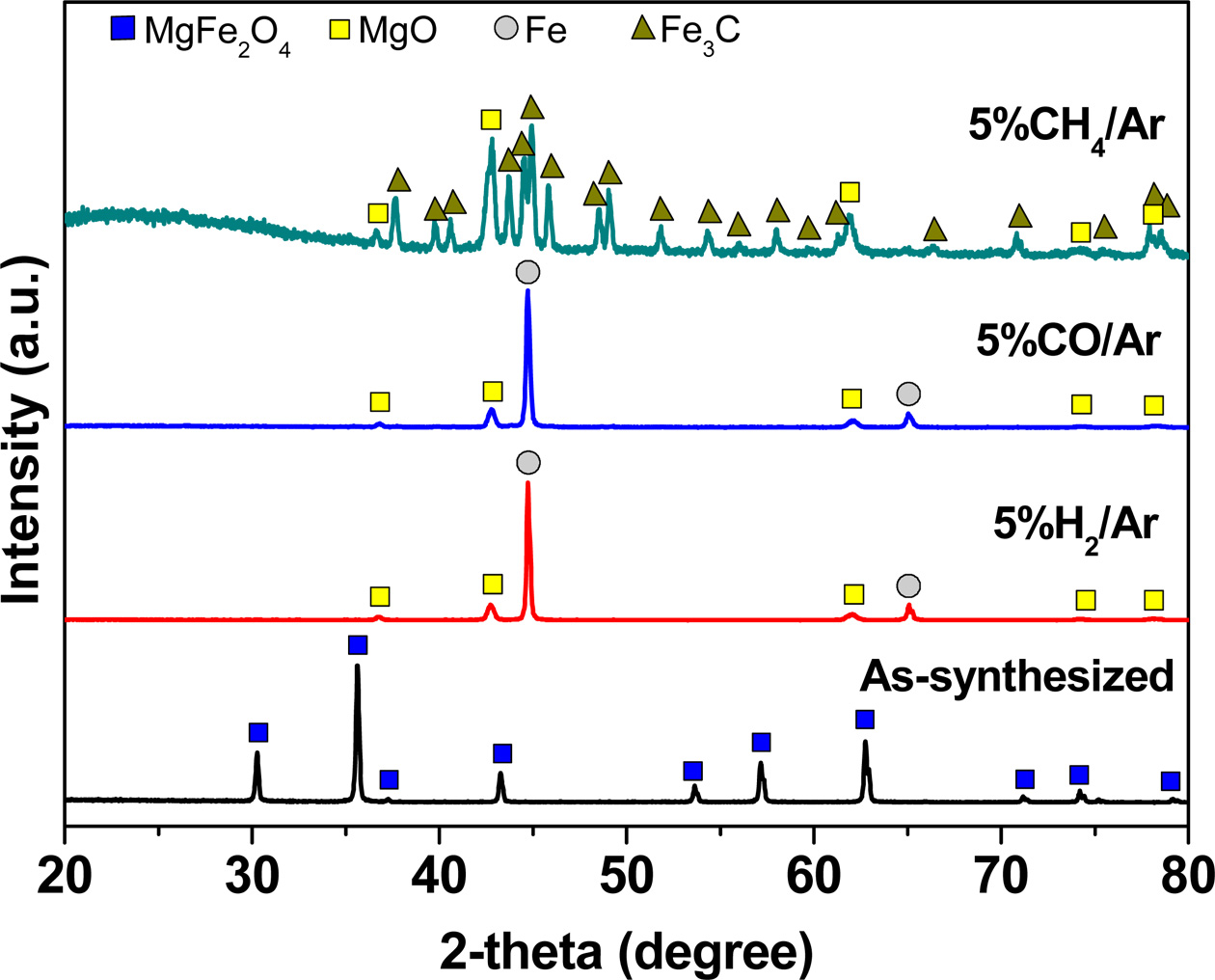
The XRD patterns of MgFe2O4 samples,
both as-synthesized and after reaction with various reducing gases,
are shown in Fig. 1. MgFe2O4 powder synthesized
at 1,200 °C for 3 h in air formed a single spinel phase without any
impurities. MgFe2O4 powders reduced in 5% H2/Ar
and 5% CO/Ar at 900 °C for 1 h showed two phases with independent
diffraction peaks of MgO and Fe. Alternatively, MgO and Fe3C were
observed in the MgFe2O4 powders reduced in 5% CH4/Ar
at 900 °C for 1 h. In the case of CH4, carbon can be formed by a
methane cracking reaction (CH4 → C + 2H2) and react with
Fe, resulting in the formation of Fe3C. In this regard, CO or syngas
might be better than CH4 as a fuel for MgFe2O4.
Since the reduction of Fe2O3 takes place as a stepwise
process [15], the reduction pathway of MgFe2O4 can be
suggested: MgFe2O4 → MgO/Fe2O3 →
MgO/Fe3O4 → MgO/FeO → MgO/Fe.
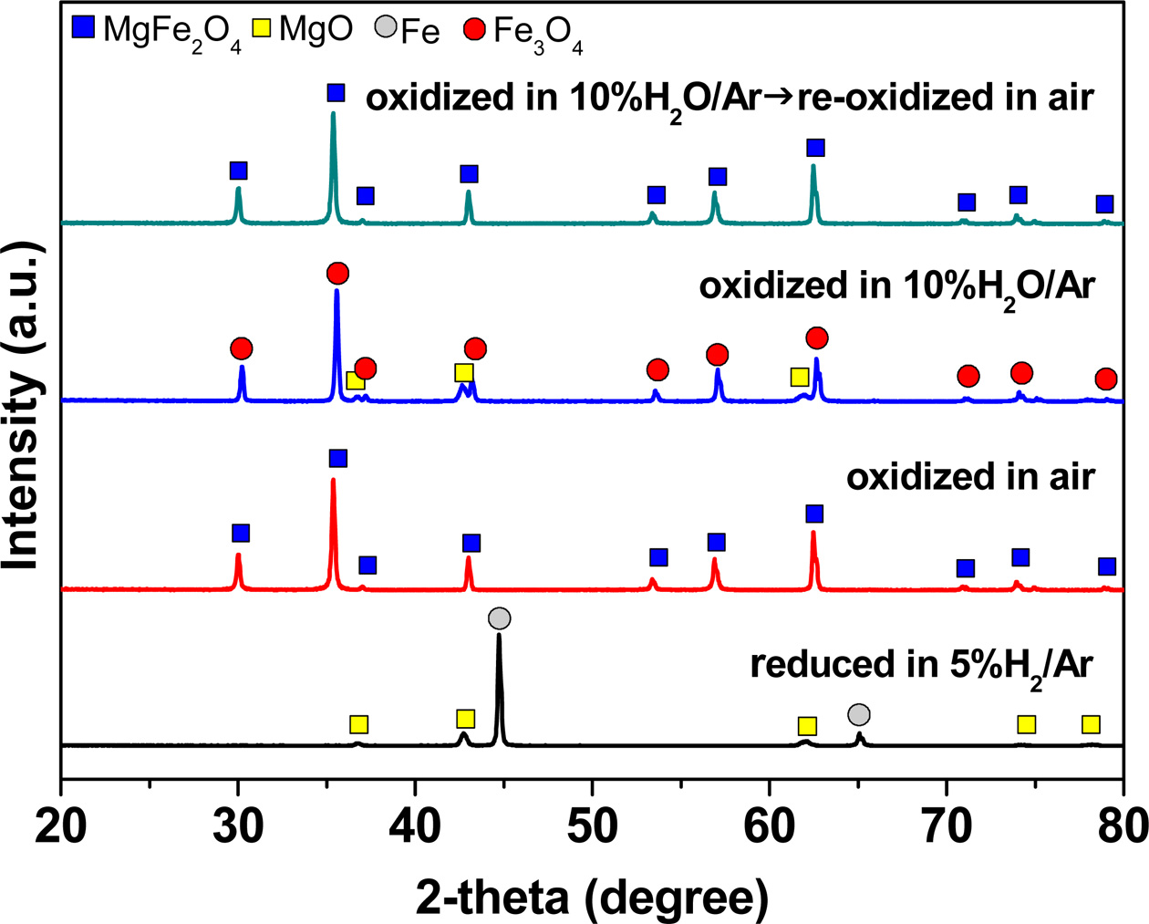
In order to confirm the redox mechanism of MgFe2O4,
phase analysis was carried out after reduction in 5% H2/Ar
followed by oxidation in air or 10% H2O/Ar. MgO
and Fe, which are the reduced products of MgFe2O4 in a 5%
H2/Ar atmosphere, formed a single phase of MgFe2O4
after oxidation in air, as shown in Fig. 2. On the contrary, the samples
oxidized by 10% H2O/Ar existed in two phases, i.e., MgO and Fe3O4,
rather than a single phase of MgFe2O4. It has also been
reported that Fe could only be oxidized to Fe3O4 under
steam [20, 21]. However, when the sample oxidized in 10% H2O/Ar was
re-oxidized by air, a single phase of MgFe2O4 formed, as
shown in Fig. 2.
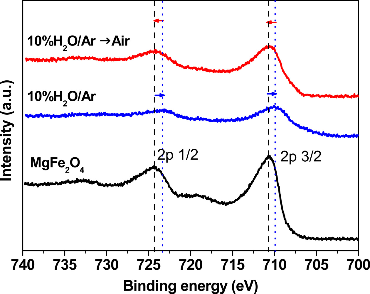
XPS analysis was also carried out in order to confirm the
valence state of Fe in MgFe2O4 before and after the
oxidation reaction at 900 oC for 1 h. The XPS spectra obtained
for the various atmospheres are shown in Fig. 3. The binding energies of Fe
2p3/2 and Fe 2p1/2 in Fe2O3 are 711.0 and 724.6 eV,
respectively [22]. In the case of Fe3O4, the peak
positions of Fe 2p3/2 and Fe 2p1/2 shift to lower binding energies of 710.56
and 724.07 eV, respectively [22]. The binding energies of Fe 2p3/2 and Fe 2p1/2
in MgFe2O4 in this study were 710.8 and 724.4 eV,
respectively, which indicates that the valence state of Fe in MgFe2O4
is 3+. Alternatively, the binding energies of Fe 2p3/2 and Fe 2p1/2 in the
sample oxidized in 10% H2O/Ar were shifted to lower binding energies
of 709.9 and 723.4 eV, respectively. These results correspond to the peak positions of
Fe3O4, indicating that
the valence state of Fe in the sample oxidized in 10% H2O/Ar is a
mix of 2+ and 3+. Interestingly, the peak positions of Fe 2p3/2 and Fe 2p1/2 in
the sample re-oxidized in air are identical to those of MgFe2O4.
Based on the phase analysis and the XPS results, we can
confirm the redox mechanism of MgFe2O4 at 900 °C. The
reduction reactions of MgFe2O4 with various gases in the
fuel reactor can be described as follows.
MgFe2O4 (s) + 3H2 (g) →
MgO (s) + 2Fe (s) + 3H2O (g) (4)
MgFe2O4 (s) + 3CO (g) → MgO (s) + 2Fe (s) + 3CO2 (g) (5)
MgFe2O4 (s) + 17/12CH4 (g)
→
MgO (s) + 2/3Fe3C (s) + 3/2H2O (g) + 3/4CO2 (g) + 4/3H2
(g) (6)
When the reduced MgFe2O4 (MgO/Fe)
was oxidized in air, the product was a single phase of MgFe2O4,
as shown in Fig. 2. Therefore, the reduced MgFe2O4
(MgO/Fe) reacts with oxygen in air to induce the oxidation reaction as follows.
MgO (s) + 2Fe (s) + 3/2O2 (g) → MgFe2O4
(s) (7)
Fe could only be oxidized to Fe3O4
under steam. In the steam reactor, the reduced MgFe2O4
(MgO/Fe) reacts with H2O to induce the oxidation reaction
as follows.
MgO (s) + 2Fe (s) + 8/3H2O (g) → MgO (s) + 2/3Fe3O4 (s) + 8/3H2
(g) (8)
Meanwhile, when the sample oxidized in the steam reactor
goes into the air reactor, MgO and Fe3O4 become
fully re-oxidized by oxygen and form the single phase of MgFe2O4
as follows.
MgO (s) + 2/3Fe3O4 (s) + 1/6O2
(g) → MgFe2O4 (s) (9)
Oxygen
transfer properties of MgFe2O4
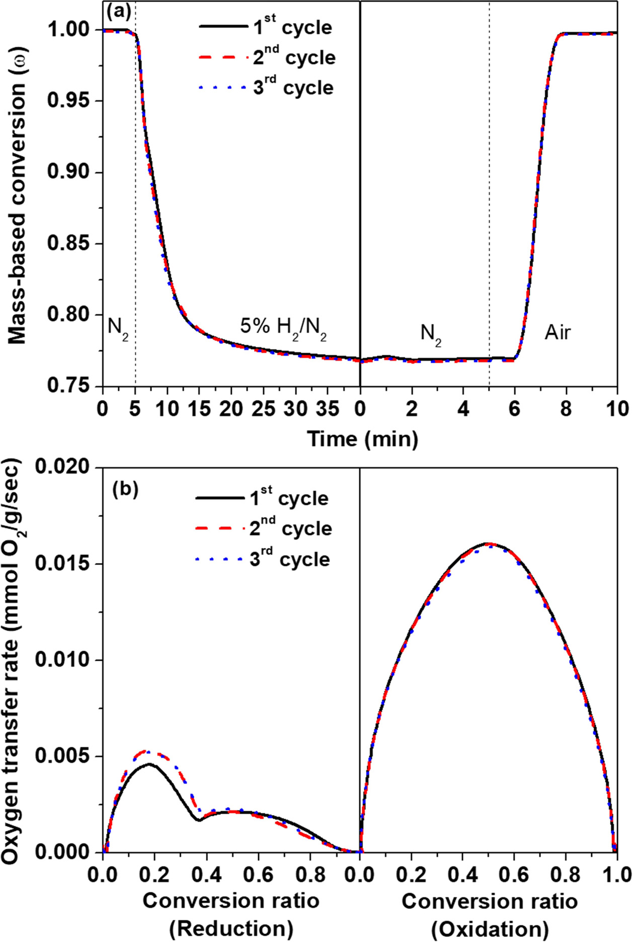
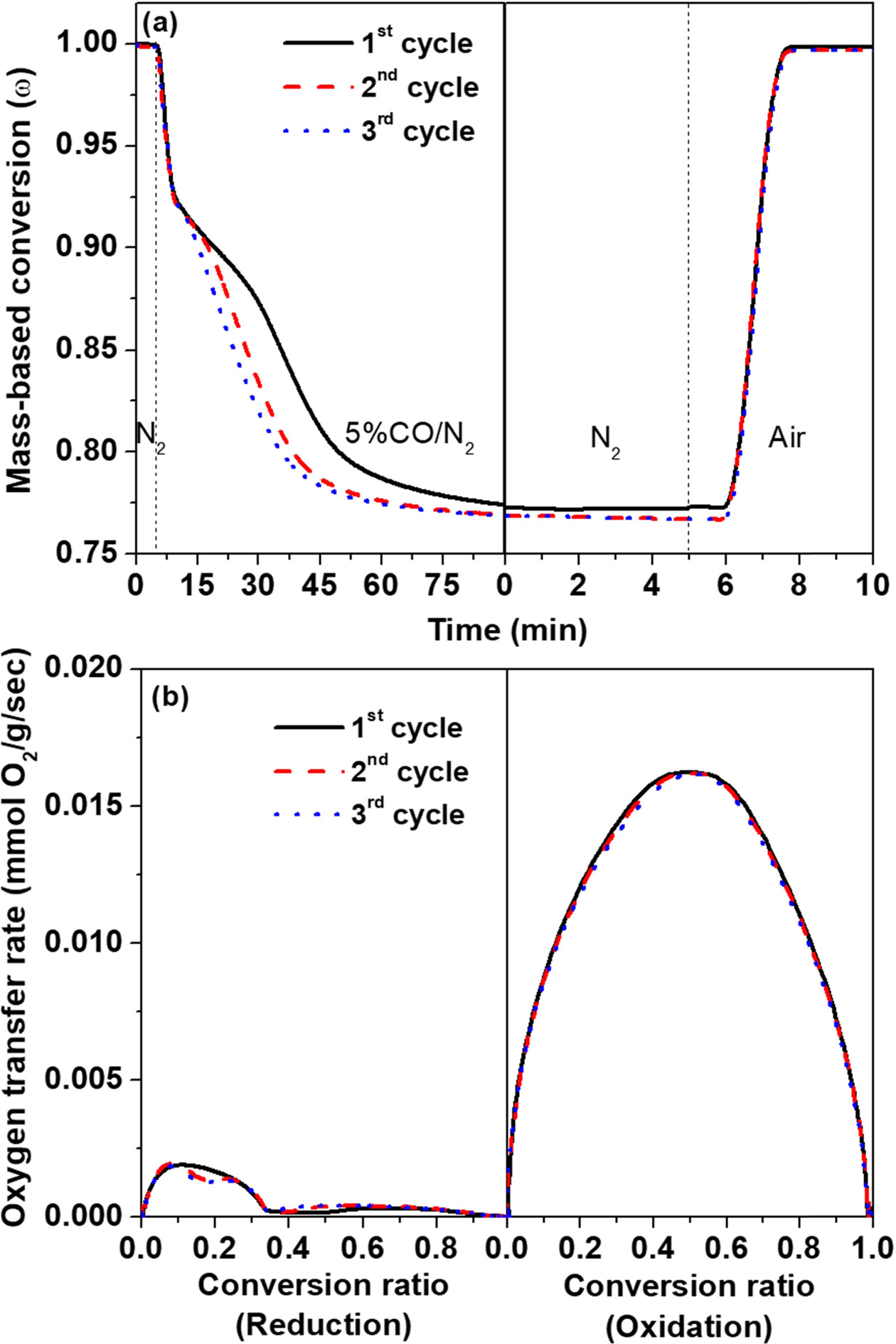
The redox cycle curves obtained using TGA at 900 °C
with 5% H2/N2 and air used as reducing and oxidizing gases,
respectively, during three redox cycles are shown in
Fig. 4(a). When oxidized by air, the weight gain is
equal to the weight loss during reduction. This indicates that the redox
reaction between MgFe2O4 and MgO/Fe, based on equation
(4) and equation (7), is reversible. This reversible redox reaction can also be
confirmed by the phase analysis, as shown in Fig. 1 and Fig. 2. While the
oxidation reaction was completed within 8 min after the oxidizing gas was
introduced, the reduction reaction takes over 40 min. The oxygen transfer rate,
which is the amount of oxygen consumed per unit time
and weight [mmol-O2/g/s], can be calculated from TGA
data (Fig. 4(a)). The oxygen transfer rate for the oxidation reaction was
clearly noted to be about three times as fast as that for the reduction
reaction, as shown in Fig. 4(b). Nam et al. reported similar results, where
that reaction rate of air oxidation was much faster than that of CH4
reduction for an Fe2O3/ZrO2 oxygen carrier
material [23]. The obtained activation energies of reduction by CH4
and oxidation by air at 900 °C were 219 and 20 kJ/mol, respectively [23].
With the 5% CO/N2 fuel, a similar trend for the
redox cycle curves and the oxygen transfer rate was observed, as
shown in Fig. 5. In particular, the oxidation curve and
oxygen transfer rate of oxidation in Figs. 4 and 5 are identical. This
indicates that the oxidation mechanism based on equation (7) is
favorable. However, the oxygen transfer rate of reduction for 5% CO/N2
is much slower compared to that for 5% H2/N2. It has been
reported that the chemical kinetic constant, Ks, for the
reaction of H2 with Fe2O3/Al2O3
oxygen carriers is significantly larger than that of CO, and the activation
energies for the reaction of H2 and CO are 8 and 14 kJ/mol,
respectively [24].
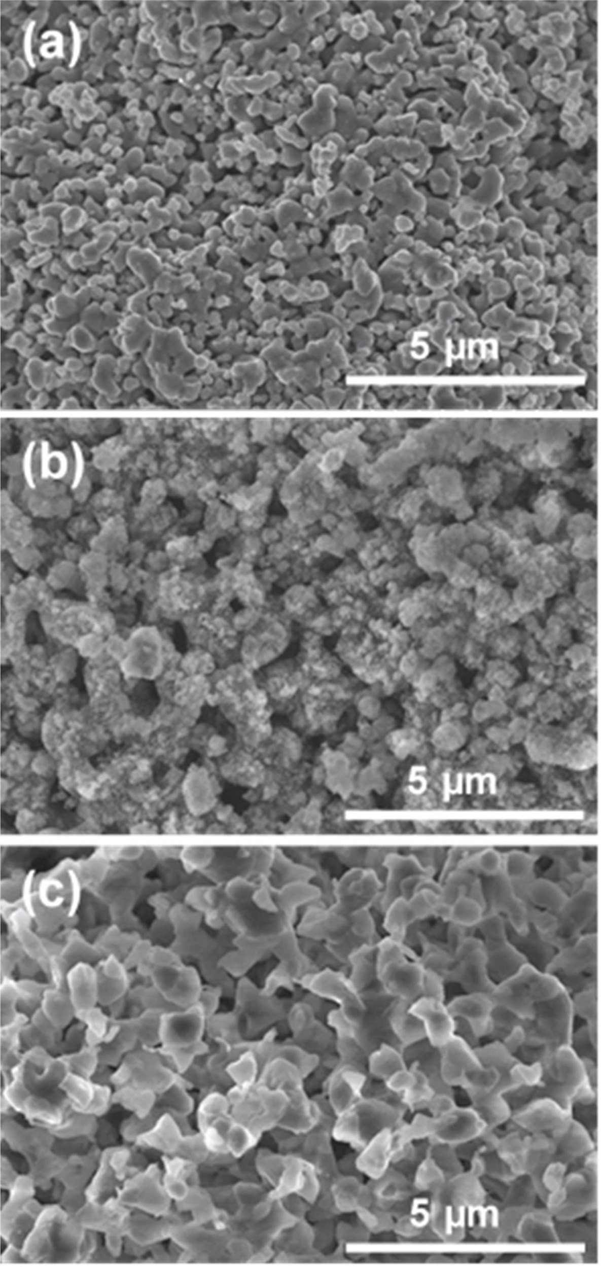
Fig. 6 shows the change of the microstructure due to the
reducing gas at the first redox cycle. The as-synthesized MgFe2O4
powder has a small granular surface with necking between particles. The MgFe2O4
powder reduced in 5% H2/N2 at 900 °C, which is
MgO/Fe, has a porous structure with smaller particles, as compared with the
initial MgFe2O4 powder; this is due to the loss of oxygen
and recombination of cations during the reduction reaction. Alternatively,
the MgFe2O4 powder
reduced in 5% CO/N2 at 900 °C shows significant
grain growth. In the case of the sample reduced by 5% CO/N2, the
sample has remained at a high temperature for a long time for complete
reduction to MgO/Fe, as shown in Fig 5(a). Therefore, a lot of grain growth has
occurred.
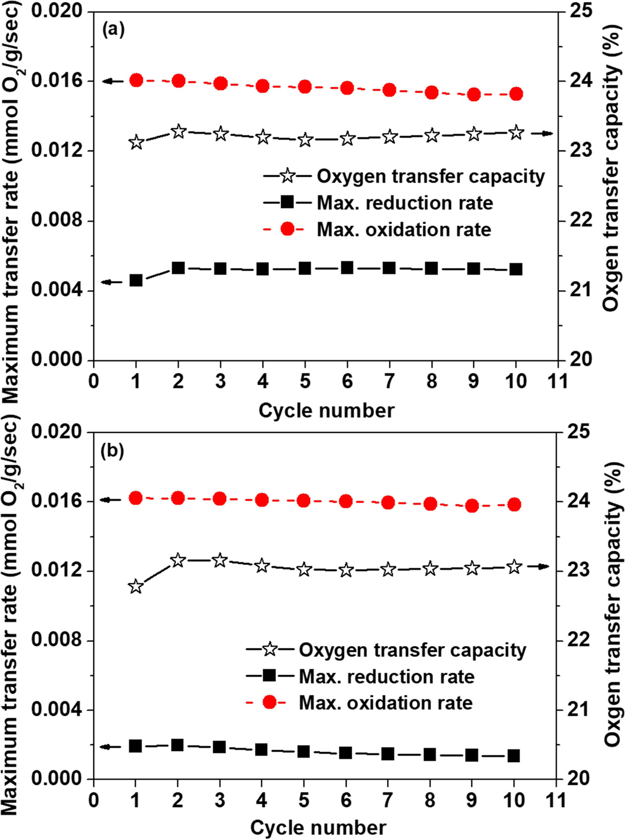
The calculated oxygen transfer capacities and maximum oxygen
transfer rates of MgFe2O4 at 900 °C with different
reducing gases according to the redox cycle number are shown in Fig.
7. The average oxygen transfer capacities of MgFe2O4
for 5% H2/N2 and 5% CO/N2 gases during 10
redox cycles were 23.2 and 23.0 wt%, respectively. The empirical oxygen
transfer capacities of MgFe2O4 were similar to the
theoretical value of 24.0 wt%, based on equation (4) and equation (5).
Moreover, no degradation of the oxygen transfer capacity or
maximum transfer rate was observed during the redox cycles. Generally,
the oxygen transfer capacity and rate decrease with
increasing redox cycle number when an irreversible phase
transition occurs. Since the redox reaction of MgFe2O4
was reversible, as shown in Fig. 2, MgFe2O4 maintained
its phase and crystal structure after redox cycling; this demonstrates the
material’s good oxygen carrier stability.
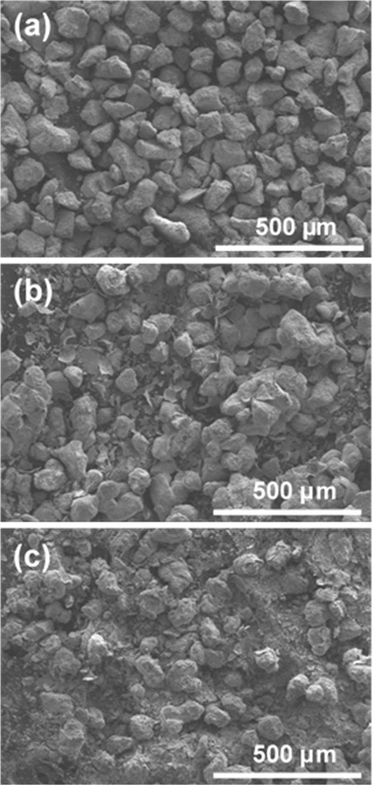
The microstructure of MgFe2O4 before
cycling and after the 10th redox cycle is shown in Fig. 8. Unlike other
Fe-based oxygen carrier materials, such Fe2O3 [25],
no agglomeration was observed after redox cycling, regardless
of the reducing gases. In general, when agglomeration
occurs, the specific surface area of the oxygen
carrier material decreases; this leads to a decrease in the
reactivity. Therefore, the microstructural stability and the phase stability
during redox cycling might explain why MgFe2O4 showed
excellent oxygen carrier stability (Fig. 7). Alternatively, the sample using 5%
CO/N2 as the reducing gas was observed to be more fragile. Attrition
is an important property of oxygen carrier materials in the case of fluidized
bed reactors. Attrition can also act as an indicator of whether an oxygen
carrier material is capable of undergoing a reaction
without any loss of particles [26]. In this regard, further
research on ways to improve the attrition resistance of MgFe2O4
should be undertaken; for example, the addition of an inorganic binder such as
Al2O3, ZrO2, CeO2 could be
beneficial [27, 28].
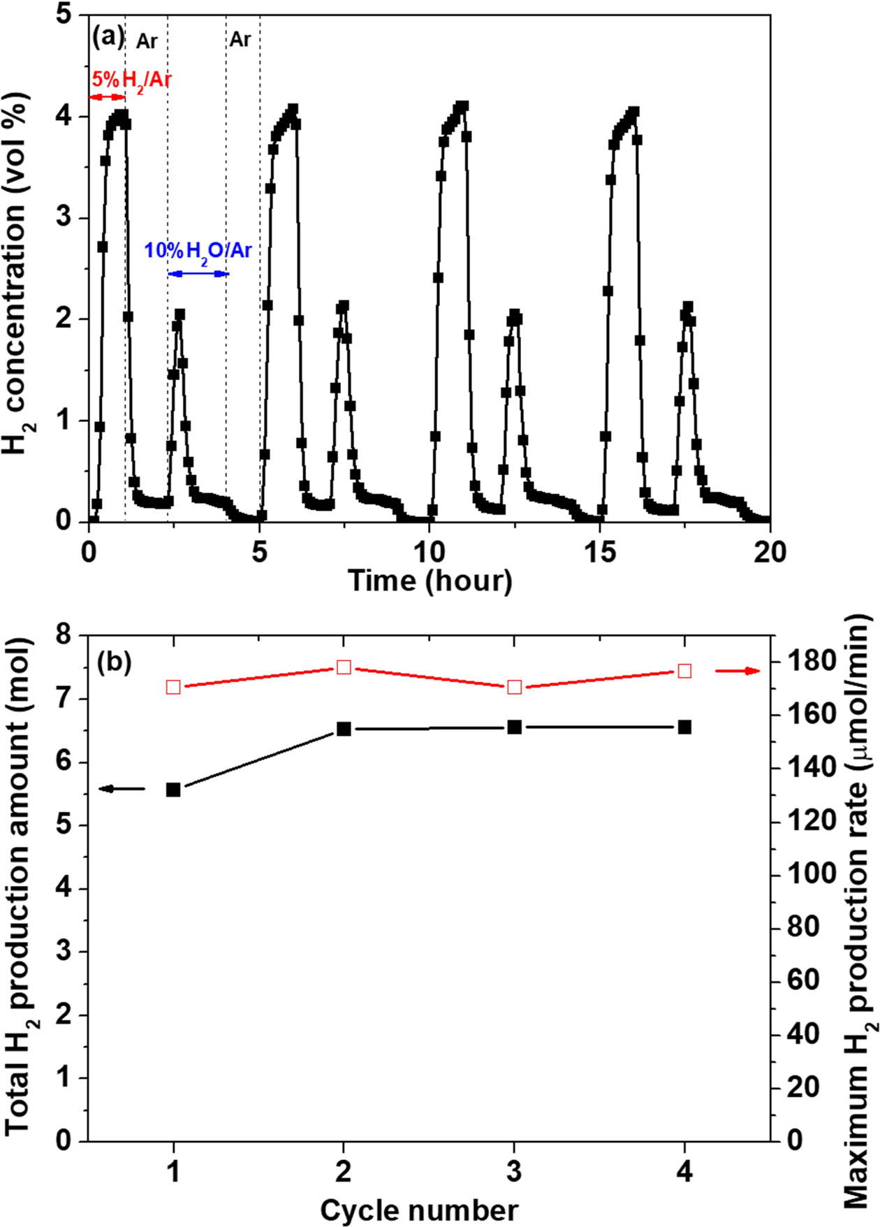
H2 production behavior of MgFe2O4
The H2 production behavior of MgFe2O4
was analyzed by GC during redox cycling using 5% H2/Ar for
reduction and 10% H2O/Ar for
oxidation at 900 °C. Fig. 9(a) shows the variation of the H2
concentration during four redox cycles. The calculated H2 production
amount and maximum production rate for the oxidation reaction are shown in Fig.
9(b). The H2 concentration during
the reduction and oxidation reactions, respectively, remained constant during redox cycling. This
indicates that the reversible reaction based on equation (8) occurs (MgO/Fe ↔
MgO/Fe3O4). Conversely, for the redox reaction using 5% H2/N2
for reduction and air for oxidation, the solid phase changes between MgO/Fe and
MgFe2O4.
Importantly, MgFe2O4
showed no significant degradation in terms of the calculated H2 production
and maximum production rate, as shown in Fig. 9(b). Assuming that the reaction rate of H2
production per minute is maintained, the average amount of H2
production for MgFe2O4 would be 2,806 L/day per unit mass
(kg).
|
Fig. 1 XRD patterns of the as-synthesized MgFe2O4 and samples reduced by various reducing gases at 900 °C for 1 h. |
|
Fig. 2 XRD patterns of MgFe2O4 according to the redox reaction at 900 °C for 1 h. |
|
Fig. 3 XPS spectra of MgFe2O4 before and after the oxidation reaction at 900 °C for 1 h. |
|
Fig. 4 (a) Redox cycle curves and (b) oxygen transfer rate of MgFe2O4 at 900 °C with 5% H2/N2 and air used as the reducing and oxidizing gases, respectively; measured by TGA. |
|
Fig. 5 (a) Redox cycle curves and (b) oxygen transfer rate of MgFe2O4 at 900 °C with 5% CO/N2 and air used as the reducing and oxidizing gases, respectively; measured by TGA. |
|
Fig. 6 FE-SEM images of MgFe2O4: (a) as-synthesized and reduced by (b) 5% H2/N2 and (c) 5% CO/N2 at 900 °C. |
|
Fig. 7 Variation of oxygen transfer capacity and maximum oxygen transfer rate of MgFe2O4 at 900 °C according to the redox cycle number for (a) 5% H2/N2 and (b) 5% CO/N2 gases; measured |
|
Fig. 8 FE-SEM images of MgFe2O4: (a) before cycling and after the 10th redox cycle at 900 °C with (b) 5% H2/N2 and (c) 5% CO/N2 reducing gases. |
|
Fig. 9 (a) Variation of the H2 concentration of MgFe2O4 with 5% H2/Ar and 10% H2O/Ar as the reducing and oxidizing gases, respectively, during four redox cycles measured by GC at 900 °C, |
The present study investigated MgFe2O4
spinel as an innovative oxygen carrier material for CLHP. MgFe2O4
reacts with various gases, such as H2, CO, and CH4, and
is reduced to MgO and Fe. The solid-state redox pathways in
the fuel, steam, and air reactors are MgFe2O4 →
MgO/Fe, MgO/Fe → MgO/Fe3O4, and MgO/Fe3O4
→ MgFe2O4, respectively. The oxygen
transfer capacity of MgFe2O4 was found to be 23
wt% when it was fully reduced to MgO/Fe; this is similar to the theoretical
value of 24 wt%. The oxygen transfer capacity and rate were maintained during
10 redox cycles because MgFe2O4 does not show any phase
or crystal structure changes or agglomeration. Similarly, both the total amount
and the maximum rate of H2 production for MgFe2O4
were maintained without significant degradation during four
redox cycles. In this regard, MgFe2O4 represents
a promising oxygen carrier material for CLHP due to its
stability and high performance. However, although MgFe2O4
shows good oxygen transfer properties and H2
production behavior, it also showed problems related to
attrition resistance. Therefore, a new approach to improve
the attrition resistance of MgFe2O4, such as the addition
of an inorganic binder, should be further investigated.
This research was supported by Basic Science Research Program through the National Research Foundation of Korea (NRF) funded by the Ministry of Education (2017R1D1A1B03031541). This work was also supported by the National Research Foundation of Korea (NRF) grant funded by the Korea government (MSIT) (No. 2018R1A4A1025528).
- 1. International Energy Outlook, (2017)
. - 2. IPCC, in 2014: Climate Change 2014: Synthesis Report, 2015, edited by R.K. Pachauri, and L.A. Meyer, Inter- governmental Panel on Climate Change Press (2015) p.151.
- 3. K. Go, S. Son, S. Kim, K. Kang, and C. Park, Int. J. Hydrogen Energy 34[3] (2009) 1301-1309.
-

- 4. R. Solunke and G. Veser, Ind. Eng. Chem. Res. 49[21] (2010) 11037-11044.
-
- 5. M. El-Shafie, S. Kambara, and Y. Hayakawa, J. Power Energy Eng. 7 (2019) 107-154.
-
- 6. J.P.V. Hook, Catal. Rev. 21 (1980) 1-51.
-
- 7. M.N. Khan and T. Shamim, Energy Procedia 61 (2014) 2034-2037.
-
- 8. B. Li, Y. Duan, D. Luebke, and B. Morreale, Appl. Energy 102 (2013) 1439-1447.
-
- 9. L.-S. Fan, L. Zeng, W. Wang, and S. Luo, Energy Environ. Sci. 5 (2012) 7254-7280.
-
- 10. F.X. Li, H.R. Kim, D. Sridhar, F. Wang, and L. Zeng, J. Chen, L.S. Fan, Energy Fuels 23[8] (2009) 4182-4189.
-
- 11. Z. Huang, F. He, Y. Feng, K. Zhao, A. Zheng, S. Chang, G. Wei, Z. Zhao, and H. Li, Energy Fuels 28[1] (2014), 183-191.
-
- 12. P. Chies, G. Lozza, A. Malandrino, M. Romano, and V. Piccolo, Int. J. Hydrogen Energy 33 (2008), 2233-2245.
-
- 13. B.S. Kwak, N.-K. Park, S.O. Ryu, J.-I. Baek, H.-J. Ryu, and M. Kang, Chem. Eng. 309 (2017) 617-627.
-
- 14. M.M. Tijani, A. Aqsha, and N. Mahinpey, Energy 138 (2017) 873-882.
-
- 15. J.H. Hwang, K.T. Lee, J. Ceram. Proc. Res. 20[1] (2019) 18-23.
- 16. P. Gupta, L.G. Velazquez-Vargas, and L.S. Fan, Energy Fuels 21[5] (2007) 2900-2908.
-
- 17. M. Rydén, E. Cleverstam, M. Johansson, A. Lyngfelt, and T. Mattisson, AIChE J. 56 (2010) 2211-2220.
-
- 18. Z. Huang, F. He, Y. Feng, K. Zhao, A. Zheng, S. Chang, G. Wei, Z. Zhao, and H. Li, Energy Fuels 28[1] (2014) 183-191.
-
- 19. S. Yang, K. Kim, J.I. Baek, J.W. Kim, J.B. Lee, C.K. Ryu, and G. Lee, Energy Fuels 26[7] (2012) 4617-4622.
-
- 20. S. Liu, F. He, Z. Huang, A. Zheng, Y. Feng, Y. Shen, H. Li, H. Wu, and P. Glarborg, Energy Fuels 30 (2016) 4151-4262.
-
- 21. Y.-C. Liu, Y. Ku, Y.-H. Tseng, H.-Y. Lee, and Y.-L. Kuo, Aerosol Air Qual. Res. 16 (2016) 2023-2032.
-
- 22. T. Yamashita and P. Hayes, Appl. Surf. Sci. 254 (2008) 2441-2449.
-
- 23. H. Nam, K. Kang, K. Bae, C. Kim, W. Cho, Y. Kim, and C. Park, Trans. Korean Hydrog. New Energy Soc. 22[2] (2011) 168-177.
- 24. A. Cabello, A. Abad, F. García-Labiano, P. Gayán, L.F. de Diego, and J. Adánez, Chem. Eng. J. 258 (2014) 265-280.
-
- 25. M. Zhu, Y. Song, S. Chen, M. Li, L. Zhang, and W. Xiang, Chem. Eng. J. 368 (2019) 812-823.
-
- 26. S. Sajen, S.K. Singh, G. Saravanan, A.H. Fakeeha, A.S. Al-Fateh, A.A. Ibrahim, M.A. Amrani, A.B. Mahindrakar, and N. Labhsetwar, J. Energy Environ. Sustain. 5 (2018) 30-40.
- 27. T. Mattisson, J. Adánez, K. Mayer, F. Snijkers, G. Williams, E. Wesker, O. Bertsch, and A. Lyngfelt, Energy Procida 63 (2014) 113-130.
-
- 28. M. Rydén, P. Moldenhauer, S. Lindqvist, T. Mattisson, and A. Lyngfelt, Powder Tech. 256 (2014) 75-86.
-
 This Article
-
2020; 21(1): 57-63
Published on Feb 28, 2020
- 10.36410/jcpr.2020.21.1.57
- Received on Aug 5, 2019
- Revised on Sep 23, 2019
- Accepted on Feb 5, 2020
Services
- Abstract
introduction
experimental procedure
results and discussion
conclusions
- Acknowledgements
- References
- Full Text PDF
Shared
Correspondence to
- Ki-Tae Lee
-
bDivision of Advanced Materials Engineering, Jeonbuk National University, Jeonbuk 54896, Republic of Korea
c- E-mail: ktlee71@jbnu.ac.kr
Clean-Energy Research Institute(CRI), Hanyang University, 222, Wangsimni-ro, Seongdong-gu, Seoul, 04763, Korea
E-mail: jcpr@hanyang.ac.kr